

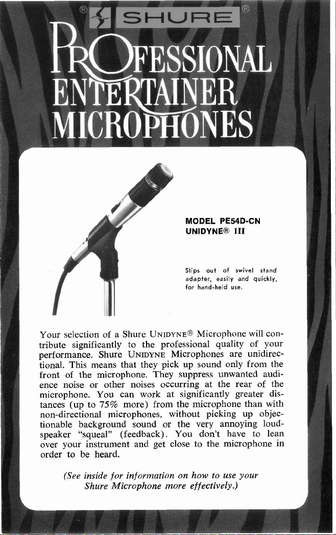
MODEL PE54D-CN
UNIDYNEB
I11
Your selection of a Shure
Slips out
adapter, easily and quickly,
for hand-held use.
UNIDYNE~
of
swivel stand
Microphone will contribute significantly to the professional quality of your
performance. Shure
UNIDYNE
Microphones are unidirectional. This means that they pick up sound only from the
front of the microphone. They suppress unwanted audience noise or other noises occurring at the rear of the
microphone. You can work at significantly greater dis-
75%
tances (up to
more) from the microphone than with
non-directional microphones, without picking up objec-
tionable background sound or the very annoying loud-
speaker "squeal" (feedback). You don't have to lean
over your instrument and get close to the microphone in
order to be heard.
(See inside for information on how to use your
Shure Microphone more effectively.)
HOW TO CONTROL FEEDBACK
performer's number one enemy in using a microphone is
A
"feedback." This is a harsh hum, howl or squeal which occurs when the microphone picks up sound from the
loudspeakers, re-amplifies and rebroadcasts it over and
over again.
The key factor in the prevention of feedback is the position of the loudspeakers in relation to the microphone.
Feedback occurs if the microphone picks up sound coming
from the loudspeakers. Keep the loudspeakers as far to the
sides as possible-so they do not point toward the microphone. Always keep the microphone pointed toward the
performer and away from the loudspeakers. When stage
monitor loudspeakers are used, make sure they are positioned in front of the performers and face the rear of the
microphone.
If you are in a room with hard walls, floor, and ceiling,
the sound from the loudspeakers may bounce back into the
microphone and create feedback. Solve this problem by
turning down the amplifier volume control and working
closer to the microphone.
(Important Note: If you cannot solve the feedback prob-
lem with your
UNIDYNE@
111 microphone, a Shure Feed-
back Controller is suggested.)
BASIC POINTS FOR PROFESSIONAL
MICROPHONE TECHNIQUE
Proper microphone technique will add to the overall effectiveness with which you project yourself to your
audience. Keep the following points in mind when using
the microphone:
1.
Maintain the proper distance from the microphone.
When you wish to achieve an intimate tonal quality,
get closer to the microphone and lower your voice. For
wide-open "driving" effects, raise your voice and back
away from the microphone so that you do not overdrive your amplifier to distortion.
2.
Don't change your distance from the microphone
needlessly, as this will affect the level of sound coming
from the loudspeakers.
3.
Consider the microphone as an instrument and practice your technique to enhance your performance.
YOUR SHURE MICROPHONE IS BUILT TO LAST!
Your Shure Microphone is ruggedly built and should give
you years of uninterrupted service; however, remember
that it is a sensitive
phone, or subjecting it to unnecessarily rough treatment.
Normal usage, of course. will not impair performance of
the unit. Use the protective carrying case to prevent damage not only when traveling, but also when storing the
n~icrophone.
MICROPHONE CHECK-LIST
I.
Check microphone impedance-is it correct for the
amplifier input being used?
1.
Check nlicrophone cable connectors to nlicrophone,
mixer and amplifier-are they tightly plugged in?
3.
Check microphone, amplifier and/or mixer.
a.
Are they turned
b. Are volume controls turned up?
IF THE MICROPHONE DOES NOT WORK
Check the above list. If the nlicrophone then does not
appear to be operating, check it on a spare cable.
microphone still does not appear to be operating, have the
microphone and cable checked by your
Entertainer Products Dealer, or write Service Department.
Shure Brothers Inc.
instrunlent. Avoid dropping the micro-
on?
If
the
Shure Professional

PHASING
To test two microphones and/or their cables for proper
phasing, connect them to an amplifier and talk or sing into
them while holding them three or four inches apart. The
sound from the speakers should be the same when talking
into either microphone or directly between them if they
are in phase with each other. If the sound drops drastically,
or if a dead spot is found when talking between the two
microphones, one of them or its cable (low impedance
only) is out of phase. All cables and microphones should
tcsted in this manner to insure that they are in phase
be
with each other.
To change the phase of a low-impedance microphone
cable, either use a Shure
change the wires connected to pins
AlSPRS Phase Reverser or inter-
2
and 3 of the connector. To change the phase of a microphone, the microphone
cartridge leads must be interchanged (see Figure 2). This
should be performed by your dealer, the Shure Factory
Service Department, or other qualified service personnel.
IMPEDANCE
Your microphone as supplied is wired for low impedance
for connection to low-impedance microphone inputs (rated
19
to
300
at
ohms). To change microphone wiring for
connection to high-impedance microphone inputs, remove
male plug insert by turning slotted setscrew inward (counterclockwise). Disconnect the two-terminal impedance
selection socket from the rear of the male insert, and
reconnect the socket in reverse position so that pin
the male insert is inserted in socket terminal
"H".
3
of
NOTE: After following the above directions, the PE54DCN with the supplied two-conductor C51CN cable will
be suitable for connection directly to high-impedance
inputs using three-pin professional audio connectors. For
?4
direct connection to
in. phone jack inputs, replace the
C51CN cable with the C5-X: 6.lm (20 ft) single-con-
ductor shielded with three-pin professional audio connector
(female) on microphone end and
?A
in. phone plug on
equipment end.

USING MORE THAN ONE MICROPHONE
It
is often desirable for a group to use a separate micro-
phone for each individual performer. In this case, the
following points should be remembered:
1.
It is best if the microphones are individually controlled
for volume through a separate Shure microphone
mixer.
If
this is not possible, it is desirable that each
performer use the sarne type and rnodel
so that the group as a whole wjil1
2.
Check the placement of the microphones with relation
of
he
"halanced."
microphone
to loudspeakers (as previously mentioned) so that
feedback is minimized.
3.
As additional microphones are added the possibility of
feedback increases. Turn off, or down, unused microphones to help solve this problem.
SHURE FEEDBACK CONTROLLER
Lets you "tune" your sound system to the acoustics of the
room. The result is more overall sound power
without
feedback. Eight linear-motion filter controls are infinitely
0
to
12
variable from
8
kHz roll-off switches attenuate low and high frequencies.
dB cut. Below
63
Hz
and Above
Can be installed between mixer or console and amplifier
for total system control, or following each microphone as
a single-channel preamplifier with feedback control.

THE VITAL LINK
BETWEEN
YOU
AND
THE AUDIENCE
SHURE PROFESSIONAL ENTERTAINER
MICROPHONES

MODEL PE54D.CN SPECIFICATIONS
Type: Dynamic, Cardioid (Unidirectional)
Frequency
Response:
Impedance: Dual. Low: Microphone rating impedance is 150 ohms (275
Output
Level Low Htgh
(at 1,000 Hz): Open Circuit Voltage'
Phasing: Low Impedance: Positive pressure on diaphragm produces
Switch: Built-in magnetic reed On-Off switch with lockplate installed
50 to 15,000 Hz (see Figure 1)
w
.MMom
m.
s-2
FIGURE
1
ohms actual) for connection to microphone inputs rated at
19 to 300 ohms.
High: Microphone impedance is "High" for connection to
high-impedance microphone inputs.
Wired for low impedance as supplied (see Page
4.)
IMPEDANCE
. . .
. . .
.
..
.
.-78.0 dB -55.0 dB
Power Level"
*O dB = 1 volt per microbar
"0 dB = 1 milliwatt with 10 microbars
positive voltage on Pin 2. (See Figure 2 and Page 4.)
High Impedance: Positive pressure on diaphragm produces
positive voltage on Pin 1. (See Figure 2 and Page 4.)
RrEO
wtTa
CnRm
. . . . . . . . . . . .
TRllNBFM1UER
FIGURE
in unlocked position. To lock switch in On position, move
to On position, loosen screw on lockplate, and turn
plate 180". Retighten screw.
(.I24 mV) (1.76 mV)
.
. .
. .
.-57.0 dB
lYPEDW
SOWET
mmm
NPLM*CL P09TrnI
2
CABLE
YLECllCN
I"
W1
lock-
f
GUARANTEE
Th~s Shure product is guaranteed In normal use to be free from electricai and
mechanical defects for a period of one year from date of purchase. Please relain proof of purchase date. This guarantee includes all parts and labor
guarantee is in lieu of any and all other guarantees or warranttes, express
~mplied, and there shall be no recovery for any consequentlai or Incidental
damages.
SHIPPING INSTRUCTIONS
Carefully repack the unlt and return it prepa~d to:
If
outs~de the United States, return the unlt to your dealer or
Service Center lor
Shure Brothers
Attention: Service Department
1501 West Shure Drive
Prl~ngton Heights, Illinois 60004
repalr. The unlt will be returned to you prepaid
\
Incorporated
Authorized
7
Thls
Shure
or

MODEL PE54D-CN SPECIFICATIONS (Continued)
Connector: Equipped with professional three-pin audio connector (male)
Shock Mount: Internal rubber vibration-isolator
Swivel Adapter: Adjustable through 90" from vertical to horizontal, to
Cable: 7
Net Weight: 255 grams (9
Packaged Weight: 1.62 kilograms (3
designed to mate with furnished cable or Cannon
Switchcraft A3
5h"-27 stand thread
6m (25 ft) two-conductor shielded. TRIPLE-FLEX@, detachable, with professional three-pin audio connectors (male
and female)
(Q.G.)
series or equivalent connector.
oz) less cable
Ib 9 oz)
XL
series.
flt
FURNISHED ACCESSORIES
Swivel Adapter: Model A25B
Carrying Case: 90L1404
OPTIONAL ACCESSORIES
Desk Stand: Models S33B, S37A, S38B, S39A, S40A
Disconnect
Adapter: Model A45
Line Matching
Transformer: Model A95 Series
Windscreen: Model
A2WS
REPLACEMENT PARTS
Cartridge: R45
Cable:
Switch: RKlOGS
Plug Element: RK4OP
Case Assembly: RK150C
C51CN
/AREA CODE 312/866-2200 CABLE SHUREMICRO
8
H
-44
SHURE BROTHERS
222
HARTREY AVENUE
EVANSTON, ILLINOIS
D
INC.
60204
U.S.A.
Copyright 1979 Printed in U.S.A.
Shure Brothers
27A1294
(SJ)
Inc.
U.S. Patents 3,132,713,
3,240,883, and D190,864
8
 Loading...