

Page 1
GENERAL
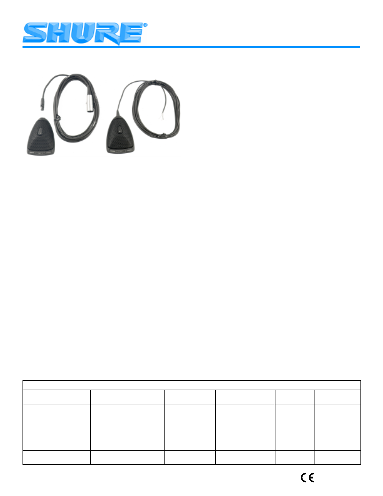
Shure Microflex
MX300 Series microphones are surfacemounted electret condenser microphones designed primarily
for mounting on conference tables, stage floors, and lecterns.
Their high sensitivity and wide frequency range make them
especially suitable for picking up speech and vocals in sound
reinforcement and recording applications. Interchangeable
cartridges provide the i nstaller w ith g reater f lexibility a nd m ake
it possible to easily reconfigure microphone coverage as the
need arises. T he M X392 a nd M X393 m odels i nclude a n i nternal preamplifier.
MX300 Series microphones take advantage of the principle that, at a barrier or boundary, the sound pressure level
doubles. When placed near a sufficiently large boundary
surface, the microphone has 6 dB higher sensitivity and approximately 3 dB greater direct-to-reverberant sound ratio.
FEATURES
•
Flat frequency response across the vocal range for
uncolored sound
•
Interchangeable cardioid, supercardioid, and omnidirectional cartridges that provide choices for applications
Sleek, low-profile design for unobtrusive appearance
•
Balanced transformerless output for increased immunity
to noise over long cable runs
•
Low susceptibility to electromagnetic hum and RFI
•
Programmable on/off switch and LED on/off indicator
Logic input/output terminals f or r emote c ontrol o r u se w ith
automatic mixers (MX392 models only)
Microflex MX300 Series User Guide
Boundary Microphones
MODEL VARIATIONS
• MX392 Models: Surface-mount microphone; in-
cludes a programmable membrane o n/of f switch, l ogic input/output terminals, an on/off indicator LED,
screw terminal connections, and attached
unterminated cable.
• MX393 Models: Surface-mount microphone; in-
cludes a programmable membrane on/off switch, an
on/off indicator LED, and a Switchcraft Tini Q-G
connector.
Selecting a Cartridge
All M icroflex microphones a re available w ith any o ne o f
three i nterchangeable cartridges. T he polar p attern of t he
original cartridge used in a particular microphone is
indicated by the model number suffix:
C = Cardioid, S = Supercardioid, O= Omnidirectional
Cardioid (C). Recommended for general sound rein-
forcement applications. Pickup angle (–3 dB) = 130°.
Supercardioid ( S). Recommended f or s ound reinforcement applications requiring narrow o r more d istant coverage. Pickup angle (–3 dB) = 115°.
Omnidirectional (O). Recommended for recording or
remote monitoring applications. Pickup angle (–3 dB) =
360°.
MICROPHONE PLACEMENT
To maintain the flattest possible low-frequency response a nd optimum r ejection o f b ackground n oise, p lace
the microphone on a flat surface that is as large as possible. The surface can be a floor, table, or lectern.
NOTE: Avoid locating microphones near reflective surfaces o ther than t he boundary surface (i.e., b eveled sides
of p ulpits or overhanging shelves). Failure to d o so will re sult in increased levels of reverberant sound.
MICROPHONE APPLICATION AND SELECTION GUIDE
Application Mounting Surface Microphone to
Sound reinforcement for
speech and vocals
Recording or remote moni-
toring of speech and vocals
Video conferencing or
computer telephony
2000, Shure Incorporated
27C2834 (TJ)
Lectern, pulpit, stage floor, or
conference table
Lectern, pulpit, stage floor, or
conference table
Lecturn, pulpit, stage floor, or
conference table
Cable Connector
Hard Wired
Hard Wired
Hard Wired
Tini Q-G
Tini Q-G
Tini Q-G
Hardwired
Cable Output
Connector
Hard Wired
Hard Wired
XLR
XLR
Hard Wired
XLR
Tini Q-G
Polar Pattern
Cardioid
Supercardioid
Cardioid
Supercardioid
Omnidirectional
Omnidirectional
Cardioid MX392/CZ
Microflex
MX392/C
MX392/S
MX393/C
MX393/S
MX392/O
MX393/O
Printed in U.S.A.
Model
Page 2

SECURING MICROPHONES TO A MOUNTING SURFACE
(FIGURE 1)
1. Remove the Phillips screw from the bottom of the microphone base, then remove the retainer.
2. Remove the grille and foam screen by carefully inserting
a pointed tool i nto t he e dge o f t he grille a nd p rying i t o pen.
3. Place the microphone in the desired location and, using
a pencil, trace the location of the screw holes through
the microphone. Then drill a starter hole for each supplied screw.
4. Cover the rear two foam pads on the microphone with
tape so that it slides more easily across the mounting
surface.
5. Install the two supplied screws in the desired location on
the mounting surface.
6. Reinstall the grille, foam screen, and retainer, and secure them with the Phillips screw.
7. Using a knife or a razor blade, cut a slot into each of the
two foam pads covering the slots below the screw holes
on the bottom of the microphone.
8. Position the microphone so that the screw holes fit over
the screw heads. Then slide the microphone so that the
screw heads are in the slots in the microphone base.
PAINTING THE MICROPHONE (FIGURE 2)
12. Reconnect the wire leads to the screw terminals.
13. Use fine sandpaper to remove any paint that may have
adhered to the bottom edges of the grille.
IMPORT ANT: For proper shielding, maintain electrical
continuity between the grille and the metal base.
14. Reinstall the retainer, grille, foam screen, and Phillips
screw.
CHANGING THE MICROPHONE CARTRIDGE (FIGURE 3)
1. Remove the Phillips screw from the bottom of the microphone base, then remove the retainer.
2. Remove the grille and foam screen by carefully inserting
a pointed tool i nto t he e dge o f t he grille a nd p rying i t o pen.
3. Remove the Phillips screw from the cartridge retaining
bracket, then remove the bracket.
4. Use your fingers to unscrew the cartridge from the microphone assembly.
5. Use your fingers to screw the replacement cartridge into
place.
6. Reinstall the cartridge retaining bracket and secure it
with the Phillips screw.
7. Reinstall the grille, foam screen, and retainer, then secure them with the Phillips screw.
1. Remove the Phillips screw from the bottom of the microphone base, then remove the retainer.
2. Lift off the retainer, grille, and foam screen. Then separate the foam screen from the grille.
3. If using an MX393 model, disconnect the Tini Q-G connector. I f you are using an MX392 model, disconnect t he
wire leads from the screw terminals, untie the knot in the
cable, and slide the cable out.
4. Remove the rubber strain relief.
5. Place the supplied plastic paint shield over the exposed
circuit board.
6. Place the supplied adhesive masking strip over the
switch panel on the front of the base.
7. Cover the connector opening on the microphone base
with the supplied round rubber plug.
8. Cleanse the surfaces to be painted with denatured alcohol or naphtha.
9. Carefully spray paint the microphone base and grille the
desired color. To avoid filling grille holes, apply paint in
a thin layer. Allow paint to dry thoroughly before reinstalling the grille and foam screen.
10. If using an MX392 model, thread the cable through the
base, then through the rubber strain relief.
11. If using an MX392 model, tie a single overhand knot in
the cable as near to the end of the cable jacket as possible. Then insert the rubber strain relief back into the
cable exit hole.
RE–ROUTING CABLE FOR BOTTOM EXIT
(FIGURE 4, MX392 MODELS ONLY)
1. Remove the Phillips screw from the bottom of the microphone base, then remove the retainer.
2. Carefully lift off the grille and foam screen, using a
pointed tool or screwdriver.
3. Disconnect the wire leads from the screw terminals on
the microphone printed circuit board.
4. Untie the knot in the cable, and slide the cable out.
5. Remove the rubber strain relief from the inside of the microphone.
6. Insert the cable through the slot between the two screw
holes, starting from the bottom of the microphone base.
7. Tie a single overhand knot in the cable from inside the
microphone. This will help prevent the cable from being
accidentally pulled out.
8. Connect the wire leads to the screw terminals on the microphone circuit board.
9. Insert the supplied round rubber plug in the unused
cable exit hole.
10. Reinstall the grille, foam screen, and retainer, and secure them with the Phillips screw.
1 1. Secure the microphone to the mounting surface. Refer
to the “Securing Microphones to a Mounting Surface”
paragraph.
2
Page 3

INTERNAL DIP SWITCH FUNCTIONS (FIGURE 5)
All MX392 and MX393 models have internal DIP switches
that allow the user to program the On/Off switch so that it fits
the application. To gain access to the DIP switches, remove
the grille retainer screw, the grille retainer, the foam screen,
and the grille, as shown in Figure 2.
MX392 LOGIC TERMINAL DEFINITIONS (FIGURE 6)
LOGIC GND Terminal: Connects to the logic ground of
an automatic mixer, switcher, or other equipment. Can be
modified to prevent ground loops. Refer to the “MX392 Logic Modifications” paragraph.
SWITCH OUT Terminal: Provides a TTL logic low when
the membrane switch is pressed. This signal is available at
all times for all switch settings. The S witch O ut f unction p rovides a m omentary c losure w hen S 1 i s O f f a nd a l atching c losure when it is On.
LED IN T erminal: Can be modified to remotely control the
LED by flipping DIP switch S3 in the microphone to the ON
position. As supplied, the LED IN terminal draws 5 Vdc.
When this is shorted to the LOGIC GROUND terminal, the
LED turns on.
MX392 LOGIC MODIFICATIONS
To gain access to the logic terminals, remove the grille retainer screw, the grille retainer, foam screen, and grille, as
shown in Figure 2.
Isolating Logic Ground from Audio Ground
1. Remove jumper R40 from the top of the circuit board.
2. Make sure LOGIC GND terminal connects to the logic
ground of the automatic mixer, switcher, or other equipment.
Changing SWITCH OUT Terminal to Always Momentary
To accommodate interface equipment requiring momentary closure of the microphone (even when the desired microphone function is latching on/off), proceed as follows:
1. Remove R45 from the top of the circuit board.
2. Reinstall R45 at location R46 on the top of the circuit
board.
Custom Switch Modifications
S4 is available for custom logic modifications. When S4 is
in the ON position, pad W4 is connected to pad W5.
DESIRED MICROPHONE FUNCTION USER ACTION REQUIRED DIP SWITCH SETTINGS
Push to Mute (As Shipped) Press and hold switch to temporarily mute micro-
phone; release switch to unmute
LED turns on when microphone is active
Push to Talk Press and hold switch to activate microphone;
release switch to mute
LED turns on when microphone is active
Push On/Push Off Press switch to toggle microphone on or off
LED turns on when microphone is active
Switch Deactivated, Microphone Always
Active
Switch Deactivated, Microphone Always
Active
Automatic Mixer Mode (MX392 models
only)
LED Always OFF S3 = ON
Short LED IN terminal to LOGIC GROUND terminal
LED Always ON
If S1=OFF, SWITCH OUT signal will be momen-
tarily logic low when switch is pressed
If S1=ON, SWITCH OUT signal will be latching
logic low when switch is pressed
Connect SWITCH OUT signal to various logic in-
puts of automatic mixer for custom functions
Connect mixer channel GATE OUT to microphone
LED IN. LED on microphone turns on when its
channel is gated on
S1 = OFF
S2 = OFF
S3 = OFF
S4 = OFF
S1 = OFF
S2 = ON
S3 = OFF
S4 = OFF
S1 = ON,
S2 = ON for muted initial state
S2 = OFF for active initial state
S3 = OFF
S4 = OFF
S4 = OFF
S3 = ON
S4 = OFF
S1 = ON or OFF
S3 = ON
S4 = OFF
NOTE: S4 is available for custom applications.
3
Page 4

SPECIFICATIONS
All measurements taken with microphone mounted on a
wooden surface 76.2 cm x 76.2 cm (30 in. x 30 in.).
Frequency Response (Figure 7)
50 to 17,000 Hz
Polar Pattern (Figure 8)
Cardioid (MX392/C, MX393/C)
Supercardioid (MX392/S, MX393/S)
Omnidirectional (MX392/O, MX393/O)
Output Impedance
EIA Rated at 150 Ω (180 Ω actual)
Sensitivity (at 1 kHz, open circuit voltage)
Cardioid Cartridge: –27.5 dBV/Pa (4.22 mV)
Supercardioid Cartridge: –26.5 dBV/Pa (4.73 mV)
Omnidirectional: –22.0 dBV/Pa (7.94 mV)
1 Pascal=94 dB SPL
Maximum Sound Pressure Level
(1 kHz at 1% Total Harmonic Distortion, 1 kΩ load)
Cardioid: 117.0 dB
Supercardioid: 116.0 dB
Omnidirectional: 111.5 dB
Signal to Noise Ratio (referenced at 94 dB SPL)
Cardioid: 71.0 dB
Supercardioid: 72.0 dB
Omnidirectional: 76.5 dB
Equivalent Output Noise (A-weighted)
Cardioid: 23.0 dB
Supercardioid: 22.0 dB
Omnidirectional: 17.5 dB
Dynamic Range
94.0 dB
Common Mode Rejection
45 dB minimum, 10 Hz to 100 kHz
Switch Attenuation
50 dB minimum
Preamplifier Output Clipping Level
–6 dBV (0.5 V)
Polarity
Positive sound pressure on diaphragm produces positive
voltage on pin 2 relative to pin 3 of output connector.
Logic Connections (MX392 Only)
LED IN: Active low (1.0v), TTL compatible. Absolute
maximum voltage: –0.7V to 50V.
SWITCH OUT: Active low (0.5V), sinks up to 20mA,
TTL compatible. Absolute maximum voltage: –0.7V to
24V (up to 50V through 3kΩ).
Power Requirements
11 to 52 Vdc phantom
2.0 mA current consumption
Environmental Requirements
Operating Temperature Range: –18° C to 57° C (0° F to
135° F)
Relative Humidity: 0 to 95%
Dimensions (Figure 9)
Certification
Conforms to European Union directives, eligible to bear
CE marking; meets European Union EMC Immunity
Requirements (EN 50082–1: 1992).
REPLACEMENT PARTS
Omnidirectional Cartridge R183. . . . . . . . . . . . . . . . . . . . .
Supercardioid Cartridge R184. . . . . . . . . . . . . . . . . . . . . . .
Cardioid Cartridge R185. . . . . . . . . . . . . . . . . . . . . . . . . . . .
NOTE: For technical data by Fax, phone 1-800-488-3297
and follow the recorded instructions. For additional technical assistance, phone Shure at (847) 866-2200. In Europe,
phone 49-7131-72140.
SHURE, the Shure logo, and MICROFLEX are registered trademarks of Shure Incorporated. Tini Q-G is a registered trademarks
of Switchcraft Incorporated.
4
Page 5

GUIDE DE L’UTILISATEUR DES MICROPHONES
PÉRIPHÉRIQUES MICROFLEX
SÉRIE MX300
GÉNÉRALITÉS
Les Shure Microflex série MX300 sont des microphones
électrostatiques à électret, à montage en surface, conçus
principalement pour les tables de conférence, planchers de
scène et lutrins. Grâce à leur haute sensibilité et vaste gamme de fréquences, ils sont particulièrement indiqués pour le
captage de la voix lors de l’amplification en direct ou des enregistrements. Les cartouches interchangeables assurent
une plus grande souplesse d’utilisation et permettent de reconfigurer aisément la portée du microphone en fonction
des besoins. Les modèles MX392 et MX393 sont dotés d’un
préamplificateur interne.
Les microphones série MX300 tirent parti du fait que lorsque le son rencontre un obstacle, le niveau de pression
acoustique double. Placé près d’une surface obstacle assez
grande, le microphone présente une sensibilité accrue de 6
dB et un rapport son direct à réverbérant accru de 3 dB.
AVANTAGES :
•
Courbe de réponse plate dans toute la gamme vocale
pour un son non coloré
•
Cartouches cardioïdes, supercardioïdes et omidirectionnelles interchangeables permettant l’adaptation optimale à chaque situation
•
Discret grâce à sa conception profilée et surbaissée
•
Sortie sans transformateur pour une immunité au bruit
accrue avec de grandes longueurs de fil
•
Basse susceptibilité aux ronflements électromagnétiques et radiofréquences
•
Interrupteur marche/arrêt programmable et témoin DEL
•
Bornes d’entrée/sortie logique pour télécommande ou
usage avec mélangeurs automatiques (modèles
MX392 seulement)
VARIANTES
Modèles MX392 : Microphone à montage en surface avec
interrupteur programmable à membrane marche/arrêt, bornes d’entrée/sortie logique, témoin marche/arrêt, connecteur à vis et câble fixe sans connecteur.
Modèles MX393 : Microphone à montage en surface avec
interrupteur programmable à membrane marche/arrêt, témoin marche/arrêt et connecteur Switchcraft Tini Q-G
.
Choix de la cartouche
Tous les microphones Microflex sont offerts avec l’une
des trois cartouches interchangeables. La courbe de directivité de la cartouche d’origine de chaque microphone est indiquée par le suffixe du numéro de modèle :
C = Cardioïde, S = S upercardioïde, O = O mnidirectionnelle
Cardioïde (C). Recommandée pour les applications de
sonorisation générale. Angle de captage (–3 dB) = 130.
Supercardioïde (S). Recommandée pour les applications de sonorisation exigeant un captage plus étroit ou à
plus grande distance. Angle de captage (–3 dB) = 115.
Omnidirectionnelle (O). Recomandée pour l’enregistrement ou le captage à distance. Angle de captage (–3 dB) =
360
PLACEMENT DU MICROPHONE
Pour obtenir une courbe de réponse la plus plate possible
et une réjection maximum des bruits de fond, placer le microphone sur une surface plane, la plus grande possible.
Cette surface peut être un plancher, une table ou un lutrin.
REMARQUE : Éviter de placer les microphones près de surfaces réverbérantes autres que les surfaces limites (par ex.,
bords en biais des lutrins ou étagères suspendues). Ce placement causerait un niveau accru du son réverbérant.
GUIDE DE SÉLECTION ET D’APPLICATION DES MICROPHONES
Application Surface de montage Connecteur
Sonorisation de la
voix
Enregistrement ou
contrôle à distance
de la voix
Vidéoconférence et
ordinateur téléfony
Lutrin, chaire, plancher de
scène ou table de
conférence
Lutrin, chaire, plancher de
scène ou table de
conférence
Lutrin, chaire, plancher de
scène ou table de
conférence
Connecteur de
microphone à
câble
Câblé
Câblé
Tini Q-G
Tini Q-G
Tini Q-G
Câblé
Câblé Tini Q-G
5
sortie de câble
Câblé
Câblé
XLR
XLR
Câblé
XLR
Courbe de directivité Modèle
Microflex
Cardioïde
Supercardioïde
Cardioïde
Supercardioïde
Omnidirectionnelle
Omnidirectionnelle
Cardioïde MX392/CZ
MX392/C
MX392/S
MX393/C
MX393/S
MX392/O
MX393/O
Page 6

FIXATION DES MICROPHONES SUR UNE SURFACE
DE MONTAGE (FIGURE 1)
1. Retirer la vis Phillips du bas de la base du microphone
et enlever la retenue.
2. Retirer la grille et l’écran de mousse en insérant avec
précaution la pointe d’un outil acéré dans le bord de la
grille et en faisant levier.
3. Placer le microphone à l’endroit désiré et, à l’aide d’un
crayon, marquer l’emplacement des vis en utilisant le
microphone comme gabarit. Percer un trou de guidage
pour chacune des vis fournies.
4. Couvrir les deux coussinets de mousse arrière du microphone de ruban adhésif de façon à ce qu’il puisse
glisser plus facilement sur la surface de montage.
5. Installer les deux vis fournies à l’endroit désiré de la surface de montage.
6. Remettre la grille, l’écran de mousse et la retenue en
place et les assujettir avec la vis Phillips.
7. À l’aide d’un couteau ou d’une lame de rasoir, découper
une fente dans chacun des coussinets de mousse couvrant les fentes situées au–dessous des trous de vis du
dessous du microphone.
8. Positionner le microphone de façon à ce que les trous
de vis se trouvent au–dessus des têtes des vis. Glisser
ensuite le microphone de façon à engager les têtes des
vis dans les fentes de la base du microphone.
PEINTURE DU MICROPHONE (FIGURE 2)
1. Retirer la vis Phillips du bas de la base du microphone
et enlever la retenue.
2. Retirer la grille et l’écran de mousse. Séparer l’écran de
mousse de la grille.
3. Dans le cas d’un modèle MX393, débrancher le connecteur T ini Q-G
. Sur les modèles MX392, débrancher les
fils des bornes à vis, défaire le noeud du câble et retirer
le câble.
4. Retirer le soulagement de traction en caoutchouc.
5. Placer la protection pour peinture en plastique fournie
sur le circuit exposé.
6. Placer le ruban adhésif de masquage fourni sur le panneau d’interrupteur du devant de la base.
7. Obturer l’ouverture de connecteur de la base du microphone à l’aide du bouchon rond en caoutchouc fourni.
8. Nettoyer les surfaces à peindre avec de l’alcool dénaturé ou du naphte.
9. Vaporiser la base et la grille du microphone de peinture
de la couleur désirée. Pour éviter de colmater les trous
de la grille, appliquer la peinture en couches minces.
Laisser sécher complètement avant de remettre la grille
et l’écran de mousse en place.
10. Sur le modèle MX392, enfiler le câble dans la base puis
dans le soulagement de contrainte en caoutchouc.
11. Sur le modèle MX392, faire un noeud simple sur le câble, aussi près que possible de l’extrémité de la gaine.
Remettre le soulagement de contrainte en caoutchouc
en place, dans le trou de sortie du câble.
12. Rebrancher les fils sur les bornes à vis.
13. Éliminer la peinture a yant é ventuellement a dhéré s ur l es
bords inférieurs d e l a g rille à l’aide d’un p apier a brasif f in.
IMPORT ANT : Pour un blindage correct, maintenir la continuité électrique entre la grille et la base métallique.
14. Remettre la retenue, la grille, l’écran de mousse e t l a vi s
Phillips en place.
REMPLACEMENT DE LA CARTOUCHE DU
MICROPHONE (FIGURE 3)
1. Retirer la vis Phillips du bas de la base du microphone
et enlever la retenue.
2. Retirer la grille et l’écran de mousse en insérant avec
précaution la point d’un outil acéré dans le bord de la
grille et en faisant levier.
3. Retirer la vis Phillips du support de la cartouche et enlever le support.
4. Avec les doigts, dévisser la cartouche du corps du microphone.
5. Procéder de même pour mettre la nouvelle cartouche
en place.
6. Remonter le support de la cartouche et l’assujettir avec
la vis Phillips.
7. Remettre la grille, l’écran de mousse et la retenue en
place et les assujettir avec la vis Phillips.
RÉACHEMINEMENT DU CÂBLE POUR LA SORTIE
PAR LE BAS (FIGURE 4, MODÈLES MX392
UNIQUEMENT)
1. Retirer la vis Phillips du dessous de la base du microphone et enlever la retenue.
2. Avec précaution, soulever la grille et l’écran de mousse
à l’aide d’un outil acéré ou d’un tournevis fin et les retirer.
3. Débrancher les fils des bornes à vis du circuit imprimé
du microphone.
4. Défaire le noeud du câble et retirer le câble.
5. Retirer le soulagement de traction en caoutchouc de
l’intérieur du microphone.
6. Insérer le câble dans les fentes se trouvant entre les
deux trous de vis, en partant du dessous de la base du
microphone.
7. Faire un noeud simple sur la partie du câble se trouvant
à l’intérieur du microphone. Ceci empêchera que le câble soit accidentellement débranché.
8. Rebrancher les f ils s ur l es b ornes à v is d u c ircuit imprimé.
9. Placer le bouchon rond en caoutchouc fourni dans le
trou de sortie de câble inutilisé.
10. Remettre la grille, l’écran de mousse et la retenue en
place et les assujettir avec la vis Phillips.
1 1. Assujettir le microphone sur la surface de montage. Voir
le paragraphe “Fixation du microphone sur la surface de
montage”.
6
Page 7

FONCTIONS DU COMMUTATEUR À POSITIONS
MULTIPLES INTERNE (FIGURE 5)
Tous les modèles MX392 et MX393 sont dotés d’un commutateur à positions multiples permettant à l’utilisateur de
programmer l’interrupteur marche/arrêt en fonction des applications. Pour accéder à ce commutateur à positions multiples, retirer la vis de retenue de la grille, la retenue, l’écran
de mousse et la grille, comme illustré à la figure 2.
DÉFINITION DES BORNES DE LOGIQUE DU MX392
(FIGURE 6)
Borne MASSE LOGIQUE : pour la connexion à la masse
logique d’une table de mélange automatique, d’un commutateur ou d’un autre appareil. Peut être modifiée pour empêcher les boucles de masse. Voir le paragraphe“Modifications de logique du MX392”.
Borne de COUPURE : procure un niveau de logique TTL
bas l orsque l ’interrupteur à membrane e st a ctionné. C e s ignal
est constamment disponible avec tous les réglages d’interrupteur. La fonction de coupure permet de couper le microphone momentanément lorsque l’interrupteur DIP 1 est sur
arrêt ou e n p ermanence l orsque l ’interrupteur e st s ur m arche.
MODIFICATIONS DE LOGIQUE DU MX392
Pour accéder aux bornes de logique, retirer la vis de retenue de la grille, la retenue, l’écran de mousse et la grille,
comme illustré à la figure 2.
Isolation de la masse logique de la masse audio
1. Retirer le cavalier R40 du dessus du circuit imprimé.
2. S’assurer que la borne de MASSE LOGIQUE est
connectée à la masse logique de la table de mélange
automatique, du commutateur ou d’un autre appareil.
Configuration de la borne de COUPURE pour la
coupure momentanée permanente
Pour l’utilisation avec un dispositif d’interface exigeant la
coupure momentanée du microphone ( même s i l a f onction d e
microphone désirée est verrouillable), procéder comme suit :
1. Retirer le cavalier R45 du dessus du circuit imprimé.
2. L’installer sur l a p osition R 46 d u d essus d u c ircuit i mprimé.
Modifications spéciales
L’interrupteur S4 permet les modifications spéciales.
Lorsqu’il est e n p osition d e M ARCHE, W 4 e st c onnecté à W5.
FONCTION DE MICROPHONE
ACTION REQUISE RÉGLAGES DES
DÉSIRÉE
Appuyer pour couper (réglage usine) Maintenir l’interrupteur enfoncé pour couper le
microphone; le relâcher pour rouvrir le micro.
Le témoin s’allume lorsque le microphone est
ouvert.
Appuyer pour parler Maintenir l’interrupteur enfoncé pour ouvrir le
microphone; le relâcher pour couper le micro.
Le témoin s’allume lorsque le microphone est
ouvert.
Appuyer pour ouvrir/couper Appuyer sur l’interrupteur pour alternativement
ouvrir et couper le microphone.
Le témoin s’allume lorsque le microphone est
ouvert.
Interrupteur désactivé, microphone ouvert
en permanence
Interrupteur désactivé, microphone ouvert
en permanence
Mode de table de mélange automatique
(modèles MX392 seulement)
Témoin toujours ÉTEINT
Relier la borne d’ENTRÉE de DEL à la MASSE
LOGIQUE
Témoin toujours allumé
Si S1 = ARRÊT, le signal de COUPURE sera
momentanément en niveau logique bas lorsque
l’interrupteur est actionné.
Si S1 = MARCHE, le signal de COUPURE
verrouillera le niveau logique bas lorsque
l’interrupteur est actionné.
Brancher le signal de COUPURE sur les diverses
entrées logiques d’une table de mélange
automatique pour obtenir les fonctions spéciales.
Raccorder la S O RTIE PORTE d e voie de la table de
mélange à l’entrée DEL du microphone. La DEL
s’allume lorsque cette voie est activée.
INTERRUPTEURS
S1 = ARRÊT
S2 = ARRÊT
S3 = ARRÊT
S4 = ARRÊT
S1 = ARRÊT
S2 = MARCHE
S3 = ARRÊT
S4 = ARRÊT
S1 = MARCHE
S2 = MARCHE pour état initial
coupé
S2 = ARRÊT pour état initial
ouvert
S3 = ARRÊT
S4 = ARRÊT
S3 = MARCHE
S4 = ARRÊT
S3 = MARCHE
S4 = ARRÊT
S1 = MARCHE ou ARRÊT
S3 = MARCHE
S4 = ARRÊT
REMARQUE : L’interrupteur S4 permet les modifications spéciales.
7
Page 8

CARACTÉRISTIQUES
Toutes les mesures ont été prises avec le microphone
monté sur une surface en bois de 76,2 cm x 76,2 cm.
Courbe de réponse (Figure 7)
50 à 17 000 Hz
Courbe de directivité (Figure 8)
Cardioïde (MX392/C, MX393/C)
Supercardioïde (MX392/S, MX393/S)
Omnidirectionnelle (MX392/O, MX393/O)
Impédance de sortie
Nominale EIA, 150 Ω (180 Ω réelle)
Sensibilité (à 1 kHz, tension en circuit ouvert)
Cartouche cardioïde : –27,5 dBV/Pa (4,22 mV)
Cartouche Supercardioïde : –26,5 dBV/Pa (4,73 mV)
Omnidirectionnelle : –22,0 dBV/Pa (7,94 mV)
1 Pascal=94 dB SPL
Pression acoustique maximum
(1 kHz avec 1% d e d istorsion h armonique t otale e t c harge
de 1 kΩ)
Cardioïde : 117,0 dB
Supercardioïde : 1 16,0 dB
Omnidirectionnelle : 1 11,5 dB
Rapport signal/bruit (mesuré avec une pression acoustique de 94 dB)
Cardioïde : 71,0 dB
Supercardioïde : 72,0 dB
Omnidirectionnelle : 76,5 dB
Bruit de sortie équivalent (pondération en A)
Cardioïde : 23,0 dB
Supercardioïde : 22,0 dB
Omnidirectionnelle : 17,5 dB
Gamme dynamique
94,0 dB
Rejet en mode commun
45 dB minimum, 10 à 100 kHz
Atténuation commutée
50 dB au minimum
Niveau d’écrêtage de sortie préampli
–6 dBV (0,5 V)
Polarité
Une pression acoustique positive sur le diaphragme produit une
tension positive sur la broche 2 par rapport à la broche 3 du
connecteur de sortie.
Connexions de logique (MX392 seulement)
ENTRÉEE DEL : Bas niveau actif (1,0 V), compatible TTL.
Tension maximum absolue : –0,7 à 50 V.
COUPURE : Bas niveau actif (0,5 V), chute à 20 mA,
compatible TTL. Tension maximum absolue : –0,7 à 24 V
(jusqu’à 50 V à 3 kohms).
Alimentation
11 à 52 V c.c. duplex
Consommation de courant 2,0 mA
Environnement
Plage de températures de fonctionnement : –18 à 57 C (0 à
135 F)
Humidité relative : 0 à 95 %
Dimensions (Figure 9)
Homologation
Conforme aux directives de l’Union Européenne, autorisé
à porter la marque CE ; conforme aux spécifications
d’immunité CEM de l’Union Européenne (EN 50082–1 :
1992).
PIÈCES DE RECHANGE
Cartouche omnidirectionnelle R183. . . . . . . . . . . . . . . . . .
Cartouche supercardioïde R184. . . . . . . . . . . . . . . . . . . . .
Cartouche cardioïde R185. . . . . . . . . . . . . . . . . . . . . . . . . .
REMARQUE : Pour toute information technique par télécopie,
composer le 1–800–488–3297 et suivre les instructions de l’enregistrement. Pour toute assistance technique supplémentaire,
appeler Shure au (847) 866–2200. En Europe, appeler le
49–7131–72140.
8
Page 9

GEBRAUCHSANLEITUNG FÜR MICROFLEX
GRENZFLÄCHENMIKROFONE DER REIHE MX300
ALLGEMEINES
Shure Microflex
Mikrofone der Reihe MX300 sind oberflächenmontierte Elektretkondensatormikrofone, die in erster Linie zur Anbringung auf Konferenztischen, Bühnenböden und Rednenpulten vorgesehen sind. Durch ihre hohe
Empfindlichkeit und den breiten Frequenzbereich eignen
sie sich besonders zur Aufnahme von Sprache und Gesang
bei der Tonverstärkung und bei Aufzeichnungsanwendungen. Austauschbare Kapseln verleihen dem Anwender größere Flexibilität und ermöglichen die einfache Neukonfiguration der Mikrofonanlage bei entsprechendem Bedarf. Die
Modelle MX392 und MX393 enthalten einen internen Vorverstärker.
Die Mikrofone der Serie MX300 beruhen auf dem Prinzip,
daß sich der Schalldruckpegel an einem Hindernis oder einer Grenzfläche verdoppelt. Bei Aufstellung in der Nähe einer hinreichend großen Grenzfläche weist das Mikrofon eine um 6 dB höhere Empfindlichkeit und ein um ungefähr 3
dB größeres Direkt/Nachhall-Tonverhältnis auf.
MERKMALE
•
Ebener Frequenzgang über den gesamten Stimmbereich für unverfärbten Klang
•
Austauschbare Kardioiden-, Superkardioiden- und Allrichtungskapseln, die optimale Ausrüstung für jede Anwendung ermöglichen
•
Glattes Flachformdesign für unauffälliges Erscheinungsbild
•
Ausgeglichene, transformatorlose Ausgabe für gesteigerte Rauschunempfindlichkeit bei langen Kabelführungen
•
Geringe Störanfälligkeit für elektromagnetische
Brumm- und Funkstörungen
•
Programmierbarer Ein/Aus-Schalter und Ein/Aus-LEDAnzeige
•
Eingabe/Ausgabe-Logikanschlüsse für Fernsteuerung
und Gebrauch mit automatischen Mischstufen (nur Modell MX392)
MODELLVARIANTEN
Modell MX392: Oberflächenmontiertes Mikrofon; einschließ-
lich programmierbarem Ein/Aus-Folienschalter, Eingabe/Ausgabe-Logikanschlüssen, Ein/Aus-LED-Anzeige, Schraubklemmenverbindungen und eingebautem unabgeschlossenem
Kabel.
Modell MX393: Oberflächenmontiertes Mikrofon; einschließlich programmierbarem Ein/Aus-Folienschalter, Ein/
Aus-LED-Anzeige und Switchcraft Tini Q-G
-Steckverbinder.
Kapselauswahl
Alle Microflex
Mikrofone sind mit einer von drei austauschbaren Kapseln lieferbar. Das Polarmuster der in einem bestimmten Mikrofon verwendeten Originalkapsel wird
durch das Modellnummer-Suffix angegeben.
C = Kardioid, S = Superkardioid, O= Alle Richtungen
Kardioid (C). Für allgemeine Tonverstärkungszwecke
empfohlen. Ansprechwinkel (–3 dB) = 130.
Superkardioid (S). Für Tonverstärkungszwecke empfohlen, die eine engere oder weiter entfernte Abdeckung erfordern. Ansprechwinkel (–3 dB) = 115.
Alle Richtungen (O). Für Aufzeichnungs– oder Fernüberwachungszwecke empfohlen. Ansprechwinkel ( –3 d B)= 3 60.
MIKROFONAUFSTELLUNG
Das Mikrofon auf einer möglichst großen, ebenen Oberfläche aufstellen, um einen möglichst ebenen Niederfrequenzgang und optimale Unterdrückung von Hintergrundgeräuschen zu erzielen. Bei der Oberfläche kann es sich um
den Boden, einen Tisch oder ein Redepult handeln.
HINWEIS: Vermeiden Sie die Aufstellung von Mikrofonen in
der Nähe anderer Reflexionsflächen a ls d er G renzfläche ( z.B.
abgeschrägte Kanten von Rednerpulten oder überhängende
Regale). Andernfalls kommt es zu erhöhten Nachhallpegeln.
ANLEITUNG ZUR MIKROFONVERWENDUNG UND -AUSWAHL
Verwendungszweck Befestigungsfläche Mikrofon/Kabel
Tonverstärkung für
Sprache und Gesang
Rednerpult, Kanzel,
Bühnenboden oder
Konferenztisch
Aufzeichnung oder
Fernüberwachung von
Sprache und Gesang
videoconferenz und
computer telephony
Rednerpult, Kanzel,
Bühnenboden oder
Konferenztisch
Rednerpult, Kanzel,
Bühnenboden oder
Konferenztisch
KabelausgangSt
Steckverbinder
Festverdrahtet
Festverdrahtet
Tini Q-G
Tini Q-G
Festverdrahtet
Tini Q-G
eckverbinder
Festverdrahtet
Festverdrahtet
XLR
XLR
Festverdrahtet
XLR
Festverdrahtet Tini Q-G
9
Polarmuster Microflex
Modell
Kardioid
Superkardioid
Kardioid
Superkardioid
Alle Richtungen
Alle Richtungen
Kardioid MX392/CZ
MX392/C
MX392/S
MX393/C
MX393/S
MX392/O
MX393/O
Page 10

ANBRINGUNG VON MIKROFONEN AUF EINER
BEFESTIGUNGSFLÄCHE (ABBILDUNG 1)
1. Die Kreuzschlitzschraube von der Unterseite des Mikrofonsockels abnehmen, dann den Haltebügel entfernen.
2. Den Grill und die Schaumstoffabschirmung ausbauen,
indem ein spitzes Werkzeug vorsichtig in die Grillkante
eingeführt und diese nach oben gedrückt wird.
3. Das Mikrofon in die gewünschte Stellung bringen und die
Position der Schraubenbohrungen m it H ilfe e ines B leistifts
durch das Mikrofon hindurch m arkieren. D anach e i ne A nsatzbohrung für jede gelieferte Schraube bohren.
4. Die beiden hinteren Schaumstoffpolster am Mikrofon
mit Klebeband abdecken, damit es leichter über die Befestigungsfläche gleitet.
5. Die beiden mitgelieferten Schrauben an der gewünschten Stelle in die Befestigungsfläche einschrauben.
6. Den Grill, die Schaumstoffabschirmung und den Haltebügel wieder einbauen und mit der Kreuzschlitzschraube festziehen.
7. Mit Hilfe eines Messers oder einer Rasierklinge einen
Schlitz in jedes der beiden Schaumstoffpolster schneiden, die die Schlitze zwischen den Schraubenbohrungen an der Unterseite des Mikrofons abdecken.
8. Das Mikrofon so plazieren, daß die Schraubenbohrungen über die Schraubenköpfe passen. Dann das Mikrofon so verschieben, daß sich die Schraubenköpfe in den
Schlitzen im Mikrofonsockel befinden.
LACKIEREN DES MIKROFONS (ABBILDUNG 2)
1. Die Kreuzschlitzschraube von der Unterseite des Mikrofonsockels abnehmen, dann den Haltebügel entfernen.
2. Den Haltebügel, den Grill und die Schaumstoffabschirmung abheben. Danach die Schaumstoffabschirmung
vom Grill trennen.
3. Bei Verwendung eines Modells MX393 den Tini Q-G
Steckverbinder ausstecken. Bei Verwendung eines Modells MX392 die Drahtverbindungen von den Schraubklemmen abklemmen, den Knoten im Kabel lösen und
das Kabel herausschieben.
4. Die Gummizugentlastung entfernen.
5. Die mitgelieferte Kunststoff–Lackierabdeckung über die
freiliegende Leiterplatte legen.
6. Das mitgelieferte selbsthaftende Kreppband über die
Schalttafel an der Vorderseite des Sockels kleben.
7. Die Steckeröffnung am Mikrofonsockel mit dem mitgelieferten runden Gummistopfen verschließen.
8. Die zu lackierenden Oberflächen mit denaturiertem Alkohol oder Naphtha reinigen.
9. Den Mikrofonsockel und Grill vorsichtig mit der gewünschten Farbe spritzlackieren. Lack mit einer dünnen
Schicht auftragen, damit keine Grillöcher ausgefüllt
werden. Lack gut trocknen lassen, bevor der Grill und
die Schaumstoffabschirmung wieder eingebaut werden.
10. Bei Verwendung eines Modells MX392 das Kabel durch
den Sockel und dann durch die Gummizugentlastung
einführen.
11. Bei Verwendung eines Modells MX392 einen einfachen
Sackstichknoten so nahe am Ende des Kabelmantels
wie möglich knoten. Dann die Gummizugentlastung
wieder in die Kabelöffnung einsetzen.
12. Die Drahtverbindungen wieder an die Schraubklemmen
anschließen.
13. Etwaige Lackreste an den Unterkanten des Grills mit feinem Sandpapier abschmirgeln.
WICHTIG: Zur sachgemäßen Abschirmung den elektrischen Durchgang z wischen d em G rill u nd d em M etallsokkel aufrecht erhalten.
14. Den Haltebügel, den Grill, die Schaumstoffabschirmung
und die Kreuzschlitzschraube wieder anbringen.
AUSTAUSCHEN DER MIKROFONKAPSEL
(ABBILDUNG 3)
1. Die Kreuzschlitzschraube von der Unterseite des Mikrofonsockels abnehmen, dann den Haltebügel entfernen.
2. Den Grill und die Schaumstoffabschirmung ausbauen,
indem ein spitzes Werkzeug vorsichtig in die Grillkante
eingeführt und diese nach oben gedrückt wird.
3. Die Kreuzschlitzschraube von der Befestigungsschelle
der Kapsel abnehmen, dann die Schelle entfernen.
4. Die Kapsel mit den Fingern aus dem Mikrofongehäuse
ausschrauben.
5. Die Ersatzkapsel mit den Fingern einschrauben.
6. Die Befestigungsschelle der Kapsel wieder anbringen
und mit der Kreuzschlitzschraube festziehen.
7. Den Grill, die Schaumstoffabschirmung und den Haltebügel wieder einbauen und danach mit der Kreuzschlitzschraube festziehen.
UMLEITUNG DES KABELS FÜR AUSTRITT NACH
UNTEN (ABBILDUNG 4, NUR BEI MODELL MX392)
-
1. Die Kreuzschlitzschraube von der Unterseite des Mikrofonsockels abnehmen, dann den Haltebügel entfernen.
2. Den Grill und die Schaumstoffabschirmung vorsichtig
mit einem spitzen Werkzeug oder einem Schraubendreher abheben.
3. Die Drahtverbindungen von den Schraubklemmen an
der Leiterplatte des Mikrofons abklemmen.
4. Den Knoten im Kabel lösen und das Kabel herausschieben.
5. Die Gummizugentlastung aus dem Inneren des Mikrofons entfernen.
6. Das Kabel durch den Schlitz zwischen den beiden
Schraubenbohrungen führen; dabei an der Unterseite
des Mikrofonsockels beginnen.
7. Im Mikrofon einen einfachen Sackstichknoten in das
Kabel knoten. Dadurch kann verhindert werden, daß
das Kabel versehentlich herausgezogen wird.
8. Die Drahtverbindungen an die Schraubklemmen an der
Leiterplatte des Mikrofons anschließen.
10
Page 11

9. Den mitgelieferten runden Gummistopfen in die nicht
verwendete Kabelöffnung einsetzen.
10. Den Grill, die Schaumstoffabschirmung und den Haltebügel wieder einbauen und mit der Kreuzschlitzschraube festziehen.
11. Das Mikrofon an der Befestigungsfläche anbringen.
Siehe Abschnitt „Anbringung von Mikrofonen auf einer
Befestigungsfläche”.
INTERNE DIP–SCHALTERFUNKTIONEN (ABBILDUNG 5)
Alle Modelle MX392 und MX393 verfügen über interne
DIP-Schalter, die es dem Benutzer ermöglichen, den Ein/
Aus-Schalter entsprechend der jeweiligen Anwendungssituation zu programmieren. Die Grillsicherungsschraube,
den Haltebügel, die Schaumstoffabschirmung und den Grill,
wie in Abbildung 2 dargestellt, entfernen, um Zugriff zu den
DIP-Schaltern zu erlangen.
DEFINITIONEN DER MX392
LOGIKANSCHLUSSKLEMMEN (ABBILDUNG 6)
Anschlußklemme LOGISCHE ERDE: Stellt die Verbin-
dung zur logischen Erde einer automatischen Mischstufe,
eines Umschalters oder eines anderen Geräts her. Kann zur
Verhinderung von Erdschleifen verändert werden. Siehe
Abschnitt
„Veränderungen der MX392 Logik”.
Anschlußklemme SCHALTER AUS: Liefert einen TTLLogik-Tiefpegel, wenn der Folienschalter gedrückt wird.
Dieses Signal ist jederzeit für alle Schalterstellungen verfügbar. Die Funktion „Schalter Aus” liefert einen Wischkontakt,
wenn der Schalter 1 ausgeschaltet ist, und einen Einrastkontakt, wenn er eingeschaltet ist.
VERÄNDERUNGEN DER MX392 LOGIK
Die Grillsicherungsschraube, d en H altebügel, d ie S chaumstoffabschirmung und den Grill, wie in Abbildung 2 dargestellt, entfernen, um Zugriff zu den Logikanschlußklemmen
zu erlangen.
Isolierung der Logikerde von der Audioerde
1. Den Jumper R40 von der Oberseite der Leiterplatte ab-
nehmen.
2. Sicherstellen, daß die Anschlußklemme LOGISCHE
ERDE die Verbindung zur logischen Erde einer automatischen Mischstufe, eines Umschalters oder eines anderen Geräts herstellt.
Änderung der Anschlußklemme SCHALTER AUS zu
$Immer Wischkontakt’
Folgendermaßen vorgehen, um den Anforderungen von
Schnittstellengeräten zu entsprechen, die einen Wischkontakt des Mikrofons benötigen (selbst wenn die gewünschte
Mikrofonfunktion Einrast–Ein/Aus ist):
1. R45 von der Oberseite der Leiterplatte abnehmen.
2. R45 an der Position R46 der Oberseite der Leiterplatte
wieder anbringen.
Kundenspezifische Schalteränderungen
S4 steht für kundenspezifische Logikänderungen zur Verfügung. Wenn sich S4 in der Stellung EIN befindet, ist der
Anschlußfleck W4 mit dem Anschlußfleck W5 verbunden.
GEWÜNSCHTE MIKROFONFUNKTION ERFORDERLICHE BENUTZERMASSNAHME DIP–SCHALTERSTELLUNGEN
Drücken zum Stummschalten
(Werkseinstellung)
Drücken zum Sprechen Den Schalter niederdrücken und festhalten, um das
Drücken zum Ein–/Ausschalten Den Schalter drücken, um das Mikrofon ein– oder
Schalter deaktiviert, Mikrofon immer
aktiv
Den Schalter niederdrücken und festhalten, um das
Mikrofon vorübergehend stummzuschalten; den
Schalter loslassen, um die Stummschaltung
aufzuheben
LED leuchtet auf, wenn das Mikrofon aktiv ist
Mikrofon zu aktivieren; den Schalter loslassen, um
das Mikrofon stummzuschalten
LED leuchtet auf, wenn das Mikrofon aktiv ist
auszuschalten
LED leuchtet auf, wenn das Mikrofon aktiv ist
LED immer AUS S3 = EIN
S1 = AUS
S2 = AUS
S3 = AUS
S4 = AUS
S1 = AUS
S2 = EIN
S3 = AUS
S4 = AUS
S1 = EIN
S2 = EIN für stummen
Anfangszustand
S2 = AUS für aktiven
Anfangszustand
S3 = AUS
S4 = AUS
S4 = AUS
11
Page 12

Schalter deaktiviert, Mikrofon immer
aktiv
Automatischer Mischmodus (nur Modell
MX392)
Anschlußklemme LED EIN mit der Anschlußklemme
LOGISCHE ERDE kurzschließen
LED immer EIN
Wenn S1 = AUS, ist das Signal SCHALTER AUS
auf logischem Wisch–Tiefpegel, wenn der Schalter
gedrückt wird.
Wenn S1 = EIN, ist das Signal SCHALTER AUS auf
logischem Einrast–Tiefpegel, wenn der Schalter
gedrückt wird.
Das Signal SCHALTER AUS an diverse
Logikeingänge der automatischen Mischstufe
anschließen, um benutzerdefinierte Funktionen zu
erhalten.
Den Mischstufenkanal GATTER AUS an die
Mikrofonklemme LED EIN anschließen. Die LED am
Mikrofon leuchtet auf, wenn sein Kanal angesteuert
wird.
HINWEIS: S4 steht für kundenspezifische Verwendungszwecke zur Verfügung.
TECHNISCHE DATEN
HINWEIS: Alle Messungen erfolgten nach Befestigung des Mi-
krofons an einer Holzoberfläche mit den Maßen 7 6,2 x 7 6,2 cm.
Frequenzgang (Abbildung 7)
50 bis 17.000 Hz
Polarmuster (Abbildung 8)
Kardioid (MX392/C, MX393/C)
Superkardioid (MX392/S, MX393/S)
Alle Richtungen (MX392/O, MX393/O)
Vorverstärkerausgang–Begrenzungspegel
–6 dBV (0,5 V)
Polarität
Positiver Schalldruck an der Membran erzeugt positive
Spannung an Stift 2 in bezug auf Stift 3 des Ausgangssteckverbinders.
Logische Verbindungen (nur bei MX392)
LED EIN: Aktiver Tiefpegel (1,0V), TTL–kompatibel.
Absolute Maximalspannung: –0,7 V bis 50 V.
Ausgangsimpedanz
EIA-Nennwert: 150 Ω (Ist-Wert: 180 Ohm)
Empfindlichkeit (bei 1 kHz, Leerlaufspannung)
Kardioidenkapsel: –27,5 dBV/Pa (4,22 mV)
Superkardioidenkapsel: –26,5 dBV/Pa (4,73 mV)
Allrichtungskapsel: –22,0 dBV/Pa (7,94 mV)
1 Pascal=94 dB SPL
Maximaler Schalldruckpegel (1 kHz bei 1 % harmonischer Gesamtverzerrung, 1 kΩ Last)
Kardioid: 117,0 dB
Superkardioid: 116,0 dB
Alle Richtungen: 111,5 dB
Rauschabstand (in bezug auf 94 dB Schalldruckpegel)
Kardioid: 71,0 dB
Superkardioid: 72,0 dB
Alle Richtungen: 76,5 dB
Äquivalent–Schalldruckpegel-Ausgangsrauschen
SCHAL TER AUS: Aktiver T iefpegel ( 0,5V), sinkt auf bis zu
20 mA ab, TTL–kompatibel. Absolute Maximalspannung:
–0,7 V bis 24 V (bis zu 50 V bei bis zu 3 kΩ).
Leistungsbedarf
11 bis 52 V Phantom-Gleichspannung
2,0 mA Stromverbrauch
Umweltbedingungen
Betriebstemperaturbereich: –18 bis 57 C
Relative Feuchtigkeit: 0 bis 95 %
Abmessungen (Abbildung 9)
Zertifizierung
Entspricht den Richtlinien der Europäischen Union, darf
das CE-Zeichen tragen; erfüllt die Anforderungen der
Europäischen Union für elektromagnetische Verträglichkeit (EN 50082–1: 1992).
(mit A-Gewichtung)
Kardioid: 23,0 dB
Superkardioid: 22,0 dB
Alle Richtungen: 17,5 dB
Dynamikbereich
94,0 dB
Gleichtaktunterdrückung
mindestens 45 dB, 10 Hz bis 100 kHz
Schalterdämpfung
mindestens 50 dB
ERSATZTEILE
Allrichtungskapsel R183. . . . . . . . . . . . . . . . . . . . . . . . . . . .
Superkardioidenkapsel R184. . . . . . . . . . . . . . . . . . . . . . . .
Kardioidenkapsel R185. . . . . . . . . . . . . . . . . . . . . . . . . . . . .
HINWEIS: Faxabruf technischer Daten unter der Rufnummer
1–800–488–3297 (nur innerhalb der USA), dabei Anleitungen
des Anrufbeantworters befolgen. Weitere technische Unterstützung wird von S hure u nter der R ufnummer + +1 ( 847) 866–2200
geleistet. In Europa bitte ++49 (7131) 72140 anrufen.
S3 = EIN
S4 = AUS
S1 = EIN oder AUS
S3 = EIN
S4 = AUS
12
Page 13

GUIA DEL USUARIO DE MICROFONOS DE
FRONTERA MICROFLEX
SERIE MX300
GENERALIDADES
Los micrófonos Microflex serie MX300 de Shure son micrófonos de condensador d e e lectreto q ue s e m ontan e n s uperficies planas, diseñados primordialmente para montarse
en mesas de conferencias, pisos de escenarios y atriles. S u
alta sensibilidad y amplia g ama d e f recuencias l os hace p articularmente útiles para la captación de oradores o cantantes
para situaciones de refuerzo o de grabación de sonido. Los
cartuchos intercambiables permiten al instalador mayor flexibilidad y permiten reconfigurar los patrones de cobertura
con micrófonos según sea necesario. Los modelos MX392
y MX393 incluyen un preamplificador interno.
Los micrófonos de la serie MX300 aprovechan el principio
físico que cuando una onda sonora choca con una frontera,
se duplica el nivel de presión acústica. Cuando estos micrófonos se colocan cerca de una superficie de frontera suficientemente grande, el micrófono tiene 6 dB adicionales de
sensibilidad y hasta 3 dB adicionales de relación de sonido
directo a sonido reflejado.
CARACTERISTICAS
•
Respuesta de frecuencia uniforme por la gama de frecuencias de voz para no alterar el tono del sonido
•
Cartuchos intercambiables con patrones de captación
de cardioide, supercardioide y omnidireccional que permiten usar la alternativa óptima para cada situación
•
Su diseño estilizado y de bajo perfil tiene una apariencia
discreta
•
Salidas equilibradas sin uso de transformadores para au mentar la inmunidad a los ruidos en tramos largos d e cable
•
Baja sensibilidad al zumbido electromagnético y a la interferencia radioeléctrica (RFI)
•
Interruptor programable y LED indicador de encendido/
apagado
•
Bornes de entrada/salida lógica para control remoto o
para usarse con consolas mezcladoras automáticas
(sólo modelo MX392)
VARIEDADES DE MODELOS
Modelos MX392: Micrófono de m ontaje e n s uperficie; i nclu-
ye un i nterruptor p rogramable d e m embrana, b ornes d e e ntrada/salida lógica, LED indicador de encendido/apagado, bornes de conexión con tornillos y cable conectado sin enchufe.
Modelos MX393: Micrófono de montaje en superficie; incluye un interruptor programable de membrana, un LED indicador
de encendido/apagado y un conector Tini Q-G
de Switchcraft.
Selección de un cartucho
Todos los micrófonos Microflex se ofrecen con uno de
tres cartuchos intercambiables. El patrón polar de captación
del cartucho originalmente usado en un micrófono particular
se designa por el sufijo que tiene en su número de modelo:
C = Cardioide, S = Supercardioide, O = Omnidireccional
Cardioide (C). Se recomienda para aplicaciones generales de refuerzo de sonido. Angulo de captación (nivel de –3
dB) = 130.
Supercardioide (S). Se recomienda para aplicaciones de
refuerzo de sonido en las cuales la zona de cobertura es
más estrecha o se requiere un alcance mayor. Angulo de
captación (nivel de –3 dB) = 115.
Omnidireccional (O). Se recomienda para aplicaciones
de grabación y de monitoreo remoto de sonido. Angulo de
captación (nivel de –3 dB) = 360
COLOCACION DE MICROFONOS
Para mantener la respuesta de frecuencia más uniforme
para las frecuencias bajas y obtener el rechazo máximo del
ruido de fondo, coloque el micrófono en una superficie plana
lo más grande posible. La superficie puede ser el piso, una
mesa o un atril.
NOT A: Evite colocar los micrófonos cerca de superficies reflectoras distintas a la de la frontera (por ejemplo, bordes biselados
de púlpitos o debajo de repisas). El no hacerlo aumenta el nivel
de sonido reverberante.
GUIA PARA LA SELECCION Y USO DE MICROFONOS
Uso Superficie de montaje Conector de
Refuerzo de sonido para
oradores o cantantes
Grabación o monitoreo
remoto de voces
videoconferencia y
telefonia de computadora
Atril, púlpito, piso de
escenario o mesa de
conferencias
Atril, púlpito, piso de
escenario o mesa de
conferencias
Atril, púlpito, piso de es-
cenario o mesa de con-
ferencias
Conector de cable
micrófono a cable
Conexión de alambre
Conexión de alambre
Tini Q-G
Tini Q-G
Conexión de alambre
Tini Q-G
Conexión de alambre Tini Q-G
13
de salida
Conexión de alambre
Conexión de alambre
XLR
XLR
Conexión de alambre
XLR
Patrón polar Modelo
Microflex
Cardioide
Supercardioide
Cardioide
Supercardioide
Omnidireccional
Omnidireccional
Cardioide MX392/CZ
MX392/C
MX392/S
MX393/C
MX393/S
MX392/O
MX393/O
Page 14

FIJACION DE MICROFONOS A LA SUPERFICIE DE
MONTAJE (FIGURA 1)
1. Quite el tornillo Phillips de la parte inferior de la base del
micrófono y después quite el retén.
2. Quite la rejilla y la pantalla de espuma insertando cuidadosamente una herramienta con punta en el borde de
la parrilla y palanquéandola para abrir la rejilla.
3. Coloque el micrófono en la posición deseada y utilice un
lápiz para m arcar l a p osición d e l os t ornillos d el m icrófono.
Taladre un agujero guía para cada uno de los tornillos.
4. Cubra los dos bloques posteriores de espuma del micrófono con cinta adhesiva para hacer que se deslicen
con mayor facilidad sobre la superficie de montaje.
5. Instale los dos tornillos provistos en la posición deseada
en la superficie de montaje.
6. Vuelva a instalar la rejilla, la pantalla de espuma y el retén y fíjelos con el tornillo Phillips.
7. Use una cuchilla o navaja para hacer una incisión en cada uno de los bloques de espuma que cubren las ranuras debajo de los agujeros de tornillo en la parte inferior
del micrófono.
8. Coloque el micrófono de manera que los agujeros de
tornillo queden sobre las cabezas de los tornillos. Después deslice el micrófono de modo que las cabezas de
los tornillos se inserten en las ranuras de la base del micrófono.
PINTURA DEL MICROFONO (FIGURA 2)
1. Quite el tornillo Phillips de la parte inferior de la base del
micrófono y después quite el retén.
2. Levante e l r etén, l a r ejilla y l a p antalla d e e spuma para q uitarlos. Después separe l a r ejilla d e l a p antalla d e e spuma.
3. Si se usa un modelo MX393, desconecte el conector
Tini Q-G
. Si se usa el modelo MX392, desconecte los
alambres de los tornillos de los bornes, suelte el nudo
del cable y extráigalo.
4. Quite el amortiguador de esfuerzos de caucho.
5. Coloque el protector de plástico contra pintura sobre la
tarjeta de circuitos expuesta.
6. Coloque la cinta adhesiva protectora sobre el tablero
del interruptor en la parte anterior de la base.
7. Cubra la abertura del conector de la base del micrófono
usando el tapón de caucho provisto.
8. Limpie las superficies que se van a pintar con alcohol
desnaturalizado o nafta.
9. Pinte la base del micrófono y la rejilla cuidadosamente
usando pintura del color deseado en atomizador. Para
evitar rellenar las aberturas de la rejilla, aplique una capa delgada de pintura. Permita que la pintura se seque
completamente antes de volver a instalar la rejilla y la
pantalla de espuma.
10. Si se usa un modelo MX392, inserte el cable por la base
y después a través del amortiguador de esfuerzos.
11. Si se usa un modelo MX392, forme un nudo sencillo con
el cable lo más cerca posible del extremo de su forro.
Después inserte el amortiguador de esfuerzos en el
agujero de salida del cable.
12. Vuelva a conectar los alambres conductores a los bornes de tornillo.
13. Use lija fina para quitar la pintura que se haya adherido
a los bordes inferiores de la rejilla.
IMPORT ANTE: Para ofrecer el blindaje correcto, manten ga la continuidad eléctrica entre la rejilla y la base metálica.
14. Vuelva a instalar el retén, la rejilla, la pantalla de espuma y el tornillo Phillips.
CAMBIO DEL CARTUCHO DEL MICROFONO
(FIGURA 3)
1. Quite el tornillo Phillips de la parte inferior de la base del
micrófono y después quite el retén.
2. Quite la rejilla y la pantalla de espuma insertando cuidadosamente una herramienta con punta en el borde de
la parrilla y palanquéandola para abrir la rejilla.
3. Saque el tornillo Phillips de la escuadra retenedora del
cartucho y quite la escuadra.
4. Use los dedos para destornillar el cartucho de la caja del
micrófono.
5. Use los dedos para atornillar el cartucho de repuesto en
su lugar.
6. Vuelva a instalar la escuadra retenedora del cartucho y
fíjela con el tornillo Phillips.
7. Vuelva a instalar la rejilla, la pantalla de espuma y el retén y después fíjelos con el tornillo Phillips.
DISPOSICION DEL CABLE PARA SALIDA POR LADO
INFERIOR (FIGURA 4, MODELO MX392 SOLAMENTE)
1. Quite el tornillo Phillips de la parte inferior de la base del
micrófono y después quite el retén.
2. Utilice una herramienta con punta o un destornillador
para levantar cuidadosamente la rejilla y la pantalla de
espuma y quitarlas.
3. Desconecte los alambres conductores de los bornes de
tornillo de la tarjeta de circuitos del micrófono.
4. Suelte el nudo del cable y extráigalo.
5. Quite el amortiguador de esfuerzos de caucho del interior del micrófono.
6. Inserte el cable a través de la ranura entre los dos agujeros de tornillo, empezando por la parte inferior de la base del micrófono.
7. Forme un nudo sencillo con el cable, en la parte interior
del micrófono. Esto ayuda a impedir que el cable sea accidentalmente extraído.
8. Conecte los alambres conductores a los bornes de tornillo de la tarjeta de circuitos del micrófono.
9. Inserte el tapón redondo de caucho provisto en el agujero de salida de cable que queda sin usarse.
10. V uelva a instalar la rejilla, la pantalla de espuma y el retén y fíjelos con el tornillo Phillips.
11. Fije el micrófono a la superficie de montaje. Consulte el p árrafo ”Fijación de micrófonos a la superficie de montaje”.
14
Page 15

FUNCIONES DE LOS INTERRUPTORES DIP
INTERNOS (FIGURA 5)
Los modelos MX392 y MX393 tienen interruptores DIP internos que permiten al usuario programar la función del interruptor de encendido de modo correspondiente al uso
deseado. Para lograr acceso a los interruptores DIP, quite
el tornillo del retén de la rejilla, el retén, la pantalla de espuma y la rejilla, como se muestra en la Figura 2.
DEFINICIONES DE LOS BORNES LOGICOS DEL MX392
(FIGURA 6)
Borne de tierra de circuitos lógicos: Se conecta al conductor de p uesta a t ierra d e l os c ircuitos l ógicos d e u na c onsola mezcladora automática, conmutador u otro equipo. Puede
modificarse para evitar los b ucles d e p uesta a t ierra. C onsulte
el párrafo ”Modificaciones de circuitos lógicos del MX392”.
Borne de salida del interruptor: Proporciona un nivel lógico bajo de TTL cuando se oprime el interruptor de membrana. Esta señal siempre está disponible para todas las
configuraciones de uso del interruptor. La función de salida
del interruptor proporciona una puesta a tierra momentánea
cuando el interruptor 1 está apagado y se engancha en
puesta a tierra cuando está encendido.
MODIFICACIONES DE CIRCUITOS LOGICOS DEL
MX392
Para lograr acceso a los bornes de configuración de circuitos
lógicos, quite el tornillo del retén de la rejilla, el retén, la pantalla
de espuma y la rejilla, como se muestra en la Figura 2.
Para aislar la tierra de circuitos lógicos de la tierra de
circuitos de audio
1. Saque el puente R40 de la parte superior de la tarjeta
de circuitos.
2. Asegúrese que el borne de tierra de circuitos lógicos
quede conectado al conductor de puesta a tierra de los
circuitos lógicos de la consola mezcladora automática,
conmutador u otro equipo.
Configuración del borne de SALIDA DEL
INTERRUPTOR para funcionamiento momentáneo
solamente
Para permitir la conexión de equipo que requiera la puesta
a tierra momentánea del micrófono (aun cuando se desea
que el micrófono se enganche en posición encendido/apagado), efectúe el procedimiento siguiente:
1. Saque el puente R45 de la parte superior de la tarjeta
de circuitos.
2. Vuelva a instalar el puente R45 en la posición R46 de la
parte superior de la tarjeta de circuitos.
Modificaciones especiales del interruptor
El interruptor S4 puede usarse para modificaciones especiales de los circuitos lógicos. Cuando el interruptor S4 está
encendido, el borne W4 se conecta con el borne W5.
FUNCION DESEADA DEL
MICROFONO
Oprima para silenciar
(configuración de fábrica)
Oprima para hablar Mantenga oprimido el interruptor para activar el micrófono;
Oprima para encender/apagar Oprima el interruptor para encenderlo y para apagarlo
Interruptor desactivado,
micrófono siempre activo
Mantenga oprimido el interruptor para silenciar el micrófono;
suéltelo para activarlo
El LED se ilumina cuando el micrófono está activo
suéltelo para silenciarlo
El LED se ilumina cuando el micrófono está activo
El LED se ilumina cuando el micrófono está activo
El LED permanece apagado S3 = ENCENDIDO
ACCION DEL USUARIO CONFIGURACION DE
INTERRUPTORES DIP
S1 = APAGADO
S2 = APAGADO
S3 = APAGADO
S4 = APAGADO
S1 = APAGADO
S2 = ENCENDIDO
S3 = APAGADO
S4 = APAGADO
S1 = ENCENDIDO
S2 = ENCENDIDO para silenciarlo
inicialmente
S2 = APAGADO para activarlo
inicialmente
S3 = APAGADO
S4 = APAGADO
S4 = APAGADO
15
Page 16

Interruptor desactivado,
micrófono siempre activo
Modalidad para consola
mezcladora automática (sólo
modelo MX392)
Conecte un alambre del borne de entrada de LED al borne
de tierra lógica
El LED permanece iluminado
Si el interruptor S1 está apagado , la señal de SALIDA DEL
INTERRUPTOR se pone en nivel bajo momentáneamente
cuando se oprime el interruptor
Si el interruptor S1 está encendido , la señal de SALIDA
DEL INTERRUPTOR se engancha en nivel bajo cuando se
oprime el interruptor
Conecte la señal de SALIDA DEL INTERRUPTOR a una de
varias entradas para señales lógicas de una consola
mezcladora automática para controlar funciones especiales.
Conecte el canal de SALIDA DE COMPUERTA de la
consola mezcladora al borne de entrada de LED del
micrófono. El LED del micrófono se ilumina cuando su canal
correspondiente se activa.
NOT A: El interruptor S4 puede usarse para funciones especiales.
ESPECIFICACIONES
Todas las mediciones se han hecho con el micrófono montado en una superficie de madera de 76,2 x 76,2 cm (30 x
30 pulg).
Respuesta de frecuencia (Figura 7)
50 a 17.000 Hz
Patrón polar (Figura 8)
Cardioide (MX392/C, MX393/C)
Supercardioide (MX392/S, MX393/S)
Omnidireccional (MX392/O, MX393/O)
Impedancia de salida
Nominal según EIA: 150 Ω (real: 180 Ω)
Sensibilidad (a 1 kHz, voltaje en circuito abierto)
Cartucho de cardioide: –27,5 dBV/Pa (4,22 mV)
Cartucho de supercardioide: –26,5 dBV/Pa (4,73 mV)
Omnidireccional: –22,0 dBV/Pa (7,94 mV)
1 Pascal=94 dB SPL
Nivel de presión acústica máximo (1 kHz con 1% de distorsión armónica total y carga de 1 kΩ)
Cardioide: 117,0 dB
Supercardioide: 116,0 dB
Omnidireccional: 111,5 dB
Relación de señal a ruido (con presión acústica de referencia de 94 dB)
Cardioide: 71,0 dB
Supercardioide: 72,0 dB
Omnidireccional: 76,5 dB
Ruido equivalente de salida (ponderación A)
Cardioide: 23,0 dB
Supercardioide: 22,0 dB
Omnidireccional: 17,5 dB
Gama dinámica
94,0 dB
Rechazo en modo común
45 dB mínimo, 10 Hz a 100 kHz
Atenuación del interruptor
50 dB mínimo
S3 = ENCENDIDO
S4 = APAGADO
S1 = ENCENDIDO o APAGADO
S3 = ENCENDIDO
S4 = APAGADO
Nivel de limitación de salida del preamplificador
–6 dBV (0,5 V)
Polaridad
Una presión positiva en el diafragma del micrófono
produce un voltaje positivo en la clavija 2 con respecto a
la clavija 3 del conector de salida.
Conexiones lógicas (sólo MX392)
ENTRADA DE LED: Se activa con nivel bajo (1,0 V),
compatible con TTL. Voltaje máximo absoluto: –0,7 V a 50
V.
SALIDA DE INTERRUPTOR: Se activa con nivel bajo
(0,5 V), consume hasta 20 mA, compatible con TTL.
Voltaje máximo absoluto: –0,7 V a 24 V (hasta 50 V con
carga de 3 kohmios).
Requisitos de alimentación
11 a 52 VCC alimentación fantasma
Consume 2,0 mA de corriente
Requisitos de entorno
Gama de temperatura de funcionamiento: –18C a 57C
(0F a 135F)
Humedad relativa: 0 a 95%
Dimensiones (Figura 9)
Certificaciones
Cumple con las directrices de la Unión Europea, califica
para llevar las marcas CE; Cumple con los requisitos de
inmunidad y compatibilidad electromagnética
(EN 50082–1: 1992).
REPUESTOS
Cartucho omnidireccional R183. . . . . . . . . . . . . . . . . . . . .
Cartucho de supercardioide R184. . . . . . . . . . . . . . . . . . .
Cartucho de cardioide R185. . . . . . . . . . . . . . . . . . . . . . . .
NOT A: Para obtener información técnica vía Fax, llame al
1–800–488–3297 y siga las instrucciones dadas en la graba ción. Para recibir soporte técnico adicional, llame a Shure al teléfono (847) 866–2200. En Europa, llame al 49–7131–72140.
16
Page 17

GUIDA D’USO DEI MICROFONI A EFFETTO DI
CONTORNO MICROFLEX
SERIE MX300
DESCRIZIONE GENERALE
I microfoni Shure Microflex serie MX300 sono microfoni a condensatore con elettrete, da fissare a superfici, concepiti principalmente per il montaggio su tavoli da conferenza, pavimenti di palcoscenici e leggii. L’elevata sensibilità e l’ampia gamma di frequenze
li rende specialmente adatti alla ricezione di segnali musicali e oratori in impianti di amplificazione sonora e registrazione. Le cartucce
intercambiabili consentono all’installatore maggiore flessibilità e
rendono agevole la riconfigurazione dell’area di copertura secondo
le necessità. I modelli MX392 e MX393 montano un preamplificatore interno.
I microfoni serie MX300 sfruttano il fenomeno fisico del raddoppiamento del livello di pressione sonora che si verifica quando le
onde sonore incidono su un ostacolo o una superficie di contorno.
Quando sono collocati in prossimità di una superficie di contorno
di dimensioni sufficientemente grandi, questi microfoni presentano
una sensibilità di 6 dB superiore e un rapporto tra energia sonora
diretta e di riverberazione maggiore di circa 3 dB.
CARATTERISTICHE
•
Risposta in frequenza costante in tutta la gamma vocale, per ottenere suoni “non colorati”.
•
Cartucce intercambiabili con diagramma di ricezione a
cardioide, supercardioide od omnidirezionale, che consentono di effettuare una scelta ottimale per ogni applicazione.
•
Profilo compatto, elegante e discreto.
•
Uscita bilanciata, senza trasformatore, per ottenere una
maggiore immunità dal rumore in lunghi tratti di cavo.
•
Bassa suscettività al ronzio elettromagnetico e all’interferenza a radiofrequenza.
•
Interruttore generale (On/Off) programmabile e LED di
segnalazione On/Off.
•
Terminali logici di ingresso/uscita per il comando a distanza o per l’uso con mixer automatici (solo per i modelli MX392).
DESCRIZIONE DEI MODELLI
Modelli MX392: microfono da fissaggio ad una superficie; inclu-
de un interruttore generale (On/Off) programmabile a membrana,
terminali logici di ingresso/uscita, un LED di segnalazione On/Off,
collegamenti dei terminali ad avvitamento e un cavo senza terminazione (collegato).
Modelli MX393: microfono da fissaggio ad una superficie; include un interruttore generale (On/Off) programmabile a membrana, un LED di segnalazione On/Off e un connettore Switchcraft Tini Q-G
.
Selezione della cartuccia
Tutti i microfoni Microflex sono disponibili con una qualunque
delle tre cartucce intercambiabili. Il diagramma polare della cartuccia originale usata in uno specifico microfono è indicato dal suffisso
del numero di modello:
C = Cardioide, S = Supercardioide, O= Omnidirezionale.
Cardioide (C). Raccomandato per applicazioni generali di amplificazione sonora. Angolo di ricezione (–3 dB) = 130.
Supercardioide (S). Raccomandato per applicazioni generali di
amplificazione sonora che richiedono una copertura più direttiva
o con portata maggiore. Angolo di ricezione (–3 dB) = 1 15.
Omnidirezionale (O). Raccomandato per applicazioni di registrazione o monitoraggio a distanza. Angolo di ricezione = 360
COLLOCAZIONE DEL MICROFONO
Per mantenere la risposta in frequenza quanto più costante possibile e una reiezione ottimale del rumore di fondo, collocare il microfono su una superficie piatta quanto più larga possibile. Tale superficie può essere un pavimento, un tavolo o un leggio.
NOT A: non collocare il microfono in prossimità di superfici riflettenti che non s iano la s uperficie d i c ontorno (ovvero, i l ati i nclinati
di un pulpito o scaffali aggettanti), altrimenti si generano livelli
maggiori di suoni di riverberazione.
APPLICAZIONE DEL MICROFONO E GUIDA ALLA SELEZIONE
Applicazione Superficie di montaggio Connettore tra
Amplificazione
sonora di segnali
musicali e oratori.
Registrazione o
monitoraggio a
distanza di segnali
musicali e oratori.
Videoconferenza e
computare telefoni
Leggio, pulpito, pavimento
di palcoscenico o tavolo da
conferenza.
Leggio, pulpito, pavimento
di palcoscenico o tavolo da
conferenza.
Leggio, pulpito, pavimento
di palcoscenico o tavolo da
conferenza.
microfono e cavo
Cablato
Cablato
Tini Q-G
Tini Q-G
Cablato
Tini Q-G
Cablato Tini Q-G
17
Connettore di
uscita del cavo
Cablato
Cablato
XLR
XLR
Cablato
XLR
Diagramma polare Modello
Microflex
Cardioide
Supercardioide
Cardioide
Supercardioide
Omnidirezionale
Omnidirezionale
Cardioide MX392/CZ
MX392/C
MX392/S
MX393/C
MX393/S
MX392/O
MX393/O
Page 18

FISSAGGIO DEL MICROFONO AD UNA SUPERFICIE
DI MONTAGGIO (FIGURA 1)
1. Svitare la vite con testa a croce Phillips dalla parte inferiore della base del microfono e togliere il ritegno.
2. Togliere la griglia e lo schermo in schiuma poliuretanica
inserendo con cautela un utensile appuntito nel bordo
della griglia e facendo leva per scalzarla.
3. Collocare il microfono nel punto desiderato e con una
matita contrassegnare la posizione dei fori per le viti attraverso il microfono, quindi trapanare un foro di guida
per ogni vite in dotazione.
4. Coprire con del nastro i due supporti posteriori di schiuma
poliuretanica sul microfono in modo che l’apparecchio possa scorrere più facilmente lungo la superficie di montaggio.
5. Avvitare nel punto desiderato della superficie di montaggio le due viti in dotazione.
6. Mettere a p osto l a g riglia, l o s chermo i n s chiuma p oliuretanica e il ritegno, e assicurarli con la vite con testa a croce
Phillips.
7. Usando un coltello o una lametta, praticare un taglio in
ciascuno dei due supporti di schiuma poliuretanica che
coprono i fori asolati sotto i fori per le viti nella parte inferiore del microfono.
8. Posizionare il microfono in modo che i fori per le viti si
trovino sopra le teste delle viti, quindi fare scorrere l’apparecchio in modo che le teste delle viti vengano a trovarsi nei fori asolati situati nella base del microfono.
VERNICIATURA DEL MICROFONO (FIGURA 2)
1. Svitare la vite con testa a croce Phillips dalla parte inferiore della base del microfono e togliere il ritegno.
2. Togliere l a griglia e lo schermo in schiuma poliuretanica,
quindi staccare lo schermo dalla griglia.
3. Se il modello usato è un MX393, scollegare il connettore
Tini Q-G
. Se il modello usato è un MX392, scollegare i
conduttori dai terminali ad avvitamento, snodare il cavo
e sfilarlo.
4. Togliere il pressacavo in gomma.
5. Collocare sulla scheda di circuiti esposta la mascherina
di plastica in dotazione di protezione dalla vernice.
6. Applicare la striscia adesiva protettiva in dotazione sul
pannello dell’interruttore, n ella p arte a nteriore d ella b ase.
7. Coprire l’apertura del connettore nella base del microfono con il tappo in gomma rotondo in dotazione.
8. Pulire con alcol denaturato o nafta le superfici da verniciare.
9. Con cautela, a pplicare a s pruzzo l a v ernice d i c olore d esiderato sulla base del microfono e sulla griglia. P er evitare
di riempire i fori della griglia, applicare uno strato sottile di
vernice. Fare asciugare la vernice prima di mettere a posto la griglia e lo schermo in schiuma poliuretanica.
10. Se il modello usato è un MX392, infilare il cavo prima attraverso la base e quindi attraverso il pressacavo in
gomma.
1 1. Se il modello usato è un MX392, fare nel cavo un nodo
semplice quanto più vicino possibile all’estremità della
sua guaina, quindi reinserire il pressacavo in gomma nel
foro di uscita del cavo.
12. Fissare nuovamente i conduttori ai terminali ad avvitamento.
13. Usare carta smeriglio fine per asportare qualsiasi traccia di vernice che aderisca ai bordi inferiori della griglia.
IMPORT ANTE: affinché la schermatura sia adeguata, non
interrompere la continuità elettrica tra la griglia e la base
metallica.
14. Mettere a posto il ritegno, la griglia e lo schermo in schiuma poliuretanica, e avvitare la vite con testa a croce
Phillips.
SOSTITUZIONE DELLA CARTUCCIA DEL
MICROFONO (FIGURA 3)
1. Svitare la vite con testa a croce Phillips dalla parte inferiore della base del microfono e togliere il ritegno.
2. Togliere la griglia e lo schermo in schiuma poliuretanica
inserendo con cautela un utensile appuntito nel bordo
della griglia e facendo leva per scalzarla.
3. Svitare la vite con testa a croce Phillips dalla staffa di ritegno della cartuccia e togliere la staffa.
4. Svitare con le dita la cartuccia dall’alloggiamento del microfono.
5. Inserire la cartuccia desiderata in posizione avvitandola
con le dita.
6. Mettere a posto la staffa di ritegno della cartuccia e assicurarla con la vite con testa a croce Phillips.
7. Mettere a posto la griglia, lo schermo in schiuma poliuretanica e il ritegno, quindi assicurarli con la vite con testa
a croce Phillips.
CAMBIO DELLA POSIZIONE DEL CAVO AFFINCHÉ
ESCA DAL BASSO (FIGURA 4, SOLO PER I MODELLI
MX392)
1. Svitare la vite con testa a croce Phillips dalla parte inferiore della base del microfono e togliere il ritegno.
2. Con c autela, t ogliere l a g riglia e l o s chermo i n sc hiuma p oliuretanica usando un utensile appuntito o un cacciavite.
3. Scollegare i conduttori dai terminali ad avvitamento sulla scheda di circuiti stampati del microfono.
4. Snodare il cavo e sfilarlo.
5. Togliere il pressacavo in gomma dall’interno del microfono.
6. Infilare il cavo attraverso il foro asolato tra i due fori per le
viti, iniziando d alla p arte i nferiore d ella base d el m icrofono.
7. Fare nel cavo u n n odo s emplice d all’interno d el m icrofono,
per evitare c he i l c avo p ossa v enire e stratto f ortuitamente.
8. Fissare i conduttori ai terminali ad avvitamento sulla
scheda di circuiti del microfono.
9. Inserire nel foro di uscita inutilizzato del cavo il tappo in
gomma rotondo in dotazione.
10. Mettere a posto la griglia, lo schermo in schiuma poliuretanica e il ritegno, assicurandoli con la vite con testa a
croce Phillips.
1 1. Fissare il microfono alla superficie di montaggio. Vedere
la sezione “Fissaggio del microfono ad una superficie di
montaggio”.
18
Page 19

FUNZIONI DEGLI INTERRUTTORI DIP INTERNI
(FIGURA 5)
Tutti i modelli MX392 e MX393 contengono degli interruttori DIP
interni che permettono di programmare l’interruttore generale (On/
Off) in base all’applicazione del microfono. Per accedere agli interruttori DIP, togliere la vite del ritegno della griglia, il ritegno, lo schermo in schiuma poliuretanica e la griglia, come illustrato nella figura
2.
DESCRIZIONI DEI TERMINALI LOGICI DEL MODELLO
MX392 (FIGURA 6)
T erminale d i M ASSA L OGICA: collega l ’apparecchio alla massa l o-
gica di un mixer automatico, di un commutatore o di altri apparecchi.
Può essere modificato per evitare anelli di massa. Vedere “Modifiche
dei terminali logici del modello MX392”.
T erminale d i USCITA INTERRUTTORE: fornisce un segnale logico TTL basso quando si preme l’interruttore a membrana. Questo
segnale è sempre disponibile per tutte le impostazioni degli interruttori. La funzione di Uscita interruttore fornisce una chiusura momentanea quando S1 è su Off ed una chiusura a ritenuta quando
è su On.
MODIFICHE DEI TERMINALI LOGICI DEL MODELLO
MX392
Per accedere ai terminali logici, togliere la vite del ritegno della
griglia, il ritegno, lo schermo in schiuma poliuretanica e la griglia,
come illustrato nella figura 2.
Isolamento della massa logica dalla massa audio
1. Togliere il ponticello R40 dalla parte superiore della
scheda di circuiti.
2. Accertarsi che il terminale di MASSA LOGICA sia collegato alla massa logica del mixer automatico, del commutatore o di qualsiasi altro apparecchio.
Modifica del terminale di USCITA INTERRUTTORE
affinché fornisca sempre una chiusura momentanea
Per adattare il microfono ad apparecchi d’interfaccia che richiedano una sua chiusura momentanea (anche quando la funzione
desiderata del microfono si inserisce e disinserisce a ritenuta), effettuare le seguenti operazioni:
1. T ogliere R45 dalla parte s uperiore della s cheda di c ircuiti.
2. Reinserire R45 nella posizione R46 nella parte superio-
re della scheda di circuiti.
Modifiche personalizzate degli interruttori
L’interruttore S4 può essere usato per modifiche personalizzate
dei circuiti logici. Quando S4 è nella posizione ON, la piazzola W4
è collegata alla piazzola W5.
FUNZIONE DESIDERATA DEL MICROFONO
Pressione sull’interruttore per disattivare
il microfono (impostazione di spedizione)
Pressione sull’interruttore quando
si desidera usare il microfono.
Pressione per attivare/disattivare
il microfono
Interruttore disattivato, microfono sempre
attivato.
Interruttore disattivato, microfono sempre
attivato.
Modalità per mixer automatico (solo per
i modelli MX392)
NOTA: l’interruttore S4 può essere usato per modifiche personalizzate.
Tenere premuto l’interruttore per disattivare
momentaneamente il microfono; rilasciare
l’interruttore per attivare il microfono.
Il LED si accende quando il microfono è attivato.
Tenere premuto l’interruttore per attivare il microfono;
rilasciare l’interruttore per disattivare il microfono.
Il LED si accende quando il microfono è attivato.
Premere l’interruttore per attivare e disattivare,
alternatamente, il microfono.
Il LED si accende quando il microfono è attivato.
LED sempre spento.
Collegare in cortocircuito il terminale d’ingresso del
LED al terminale di MASSA LOGICA.
LED sempre acceso.
Se S1=OFF, il segnale di USCITA INTERRUTTORE è
momentaneamente allo stato logico basso quando si
preme l’interruttore.
Se S1=ON, il segnale di USCITA INTERRUTTORE va
allo stato logico basso e vi rimane quando si preme
l’interruttore.
Collegare il segnale di USCITA INTERRUTTORE ai
vari ingressi logici del mixer automatico ai fini delle
funzioni personalizzate.
Collegare il canale di uscita porta (Gate Out) del mixer
all’ingresso del LED del microfono. Il LED si accende
quando il suo canale viene comandato su on dalla
porta.
OPERAZIONE NECESSARIA IMPOSTAZIONI DEGLI
INTERRUTTORI DIP
S1 = OFF
S2 = OFF
S3 = OFF
S4 = OFF
S1 = OFF
S2 = ON
S3 = OFF
S4 = OFF
S1 = ON,
S2 = ON: stato iniziale di
disattivazione.
S2 = OFF: stato iniziale di
attivazione.
S3 = OFF
S4 = OFF
S3 = ON
S4 = OFF
S3 = ON
S4 = OFF
S1 = ON oppure OFF
S3 = ON
S4 = OFF
19
Page 20

DATI TECNICI
Tutte le misure sono state eseguite con i microfoni montati su
una superficie di legno di 76,2 x 76,2 cm.
Risposta in frequenza (Figura 7)
Da 50 a 17.000 Hz
Diagramma polare (Figura 8)
Cardioide (MX392/C, MX393/C)
Supercardioide (MX392/S, MX393/S)
Omnidirezionale (MX392/O, MX393/O)
Impedenza di uscita
Valore nominale EIA di 150 Ω (valore effettivo di 180 Ω)
Sensibilità (a 1 kHz, tensione a circuito aperto)
Cartuccia per diagramma a cardioide:
–27,5 dBV/Pa (4,22 mV)
Cartuccia per diagramma a supercardioide:
–26,5 dBV/Pa (4,73 mV)
Cartuccia per diagramma omnidirezionale:
–22,0 dBV/Pa (7,94 mV)
1 Pascal=94 dB SPL
Livello massimo di pressione sonora
(1 kHz a 1% di distorsione armonica totale, carico di 1
kΩ)
Cardioide: 117,0 dB
Supercardioide: 116,0 dB
Omnidirezionale: 111,5 dB
Rapporto segnale/rumore (riferimento: 94 dB di pressione sonora)
Cardioide: 71,0 dB
Supercardioide: 72,0 dB
Omnidirezionale: 76,5 dB
Rumore di uscita equivalente (ponderato A)
Cardioide: 23,0 dB
Supercardioide: 22,0 dB
Omnidirezionale: 17,5 dB
Gamma dinamica
94,0 dB
Reiezione di modo comune
45 dB min., da 10 Hz a 100 kHz
Attenuazione dell’interruttore
50 dB min.
Livello di limitazione dell’uscita del preamplificatore
–6 dBV (0,5 V)
Polarità
Una pressione positiva sul diaframma genera una
tensione positiva sul piedino 2 rispetto al piedino 3 del
connettore di uscita.
Collegamenti logici (solo per i modelli MX392)
INGRESSO LED: stato logico attivo basso (1,0 V),
compatibile con logica TTL. Tensione assoluta massima:
da –0,7 V a 50 V.
USCITA INTERRUTTORE: stato logico attivo basso
(0,5 V), assorbimento massimo di corrente 20 mA,
compatibile con logica TTL. Tensione assoluta massima:
da –0,7 V a 24 V (fino a 50 V con 3 kohm inseriti).
Requisiti di alimentazione
Da 11 a 52 V c.c., virtuale.
Assorbimento di corrente: 2,0 mA.
Requisiti sulle condizioni ambientali
Campo della temperatura di esercizio: da –18 a 57 C
Umidità relativa: da 0 al 95%.
Dimensioni (Figura 9)
Omologazioni
Conforme alle direttive della Comunità Europea, contrassegnabile con il marchio CE; soddisfa i requisiti sull’immunità e sulla compatibilità elettromagnetica specificati dalla
CE (EN 50082–1: 1992).
RICAMBI
Cartuccia per diagramma omnidirezionale R183. . . . . . .
Cartuccia per diagramma a supercardioide R184. . . . . .
Cartuccia per diagramma a cardioide R185. . . . . . . . . . .
NOT A: per ottenere dati tecnici tramite telefax, chiamare il nu mero 1–800–488–3297 (solo negli USA) e seguire le istruzioni
registrate. Per assistenza tecnica, rivolgersi alla Shure chiamando il numero USA (847) 866–2200. In Europa, chiamare il
numero 0047–7131–72140.
20
Page 21
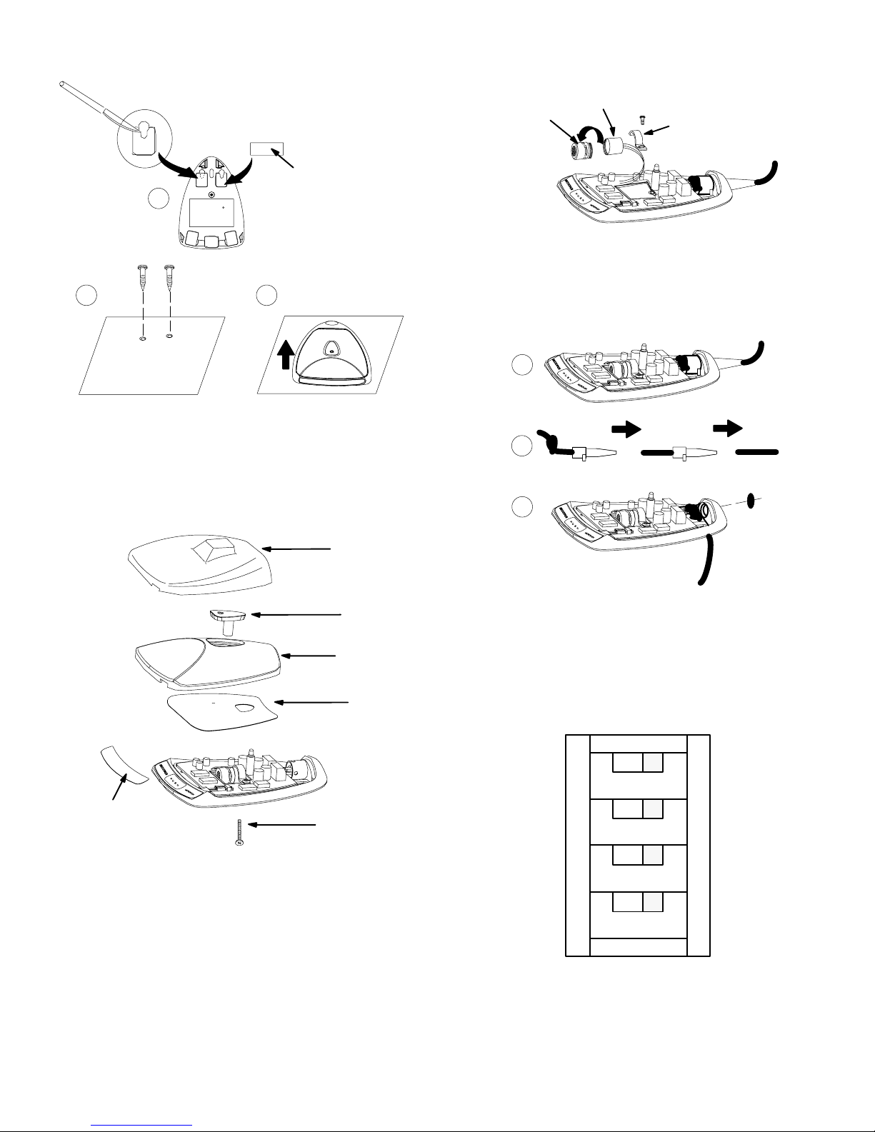
TAPE
RUBAN ADHÉSIF
KLEBEBAND
A
B
CINTA ADHESIVA
NASTRO
C
SECURING MICROPHONE TO BOUNDARY SURFACE
ADAPTATION DU MICROPHONE À LA SURFACE LIMITE
ANBRINGUNG DES MIKROFONS AUF DER GRENZFLÄCHE
FIJACION DEL MICROFONO A LA SUPERFICIE
FISSAGGIO DEL MICROFONO ALLA SUPERFICIE DI CONTORNO
FIGURE 1 • FIGURE 1 • ABBILDUNG1 • FIGURA 1 • FIGURA 1
FIGURE 3
HOUSING
LOGEMENT
GEHÄUSE
CARTRIDGE
CARTOUCHE
KAPSEL
CARTUCHO
CARTUCCIA
CAJA
ALLOGGIAMENTO
BRACKET
SUPPORT
BEFESTIGUNGSSCHELLE
ESCUADRA
STAFFA
CARTRIDGE REPLACEMENT
REMPLACEMENT DE LA CARTOUCHE
AUSTAUSCH DER KAPSEL
SUSTITUCION DE CARTUCHO
SOSTITUZIONE DELLA CARTUCCIA
• FIGURE 3 • ABBILDUNG 3 • FIGURA 3 • FIGURA 3
A
B
C
PAINT MASK
PROTECTION POUR LA PEINTURE
LACKIERABDECKUNG
PROTECTOR CONTRA PINTURA
MASCHERINA DI PROTEZIONE DALLA VERNICE
RETAINER
RETENUE
HALTEBÜGEL
RETEN
RITEGNO
GRILLE
GRILLE
GRILL
REJILLA
GRIGLIA
FOAM PAD
ÉCRAN DE MOUSSE
SCHAUMSTOFFABSCHIRMUNG
PANTALLA DE ESPUMA
SCHERMO IN SCHIUMA POLIURETANICA
PAINT MASK
PROTECTION POUR LA PEINTURE
LACKIERABDECKUNG
PROTECTOR CONTRA PINTURA
MASCHERINA DI PROTEZIONE DALLA VERNICE
RETAINING SCREW
VIS DE RETENUE
SICHERUNGSSCHRAUBE
TORNILLO DE RETEN
VITE DEL RITEGNO
DISSASSEMBL Y AND PAINT MASKING
DÉSASSEMBLAGE ET PROTECTION POUR LA PEINTURE
AUSEINANDERBAU UND LACKIERABDECKUNG
DESARMADO Y PROTECCION CONTRA PINTURA
SMONTAGGIO E APPLICAZIONE DELLE PROTEZIONI DALLA VERNICE
CONFIGURATION FOR BOTTOM CABLE EXIT
CONFIGURATION POUR SORTIE DU CÂBLE PAR LE BAS
ANORDNUNG FÜR KABELAUSTRITT NACH UNTEN
CONFIGURACION DEL CABLE PARA SALIDA POR PARTE INFERIOR
CAMBIO DELLA POSIZIONE DEL CAVO AFFINCHÉ ESCA DAL BASSO
FIGURE 4 • FIGURE 4 • ABBILDUNG4 • FIGURA 4 • FIGURA 4
ON
MARCHE
EIN
ENCENDIDO
ON
MOMENTARY
MOMENTANÉ
WISCHKONTAKT
MOMENTANEO
AZIONE MOMENTANEA
PUSH TO MUTE
APPUYER POUR COUPER
DRÜCKEN ZUM STUMMSCHALTEN
OPRIMA PARA SILENCIAR
PRESSIONE PER DISATTIVARE
LOCAL CONTROL
COMMANDE LOCALE
LOKALE STEUERUNG
CONTROL LOCAL
COMANDO LOCALE
CUSTOM
SPÉCIALE
KUNDENSPEZIFISCH
FUNCION ESPECIAL
PERSONALIZZAZIONE PERSONALIZZAZIONE
1
2
3
4
TOGGLE
ALTERNANCE M/A
KUNDENSPEZIFISCH
FUNCION ENGANCHADA
ATTIVAZIONE/DISATTIVAZIONE
PUSH TO TALK
APPUYER POUR PARLER
UMSCHALTEN
OPRIMA PARA HABLAR
PRESSIONE PER ATTIVARE
REMOTE CONTROL
COMMANDE À DISTANCE
DRÜCKEN ZUM SPRECHEN
CONTROL REMOTO
COMANDO A DISTANZA
CUSTOM
SPÉCIALE
FERNSTEUERUNG
FUNCION ESPECIAL
FIGURE 2
• FIGURE 2 • ABBILDUNG2 • FIGURA 2 • FIGURA 2
21
FIGURE 5
INTERNAL DIP SWITCHES
COMMUTATEUR À POSITIONS MULTIPLES
INTERNE DIP–SCHALTER
INTERRUPTORES DIP INTERNOS
INTERRUTTORI DIP INTERNI
• FIGURE 5 • ABBILDUNG5 • FIGURA 5 • FIGURA 5
Page 22
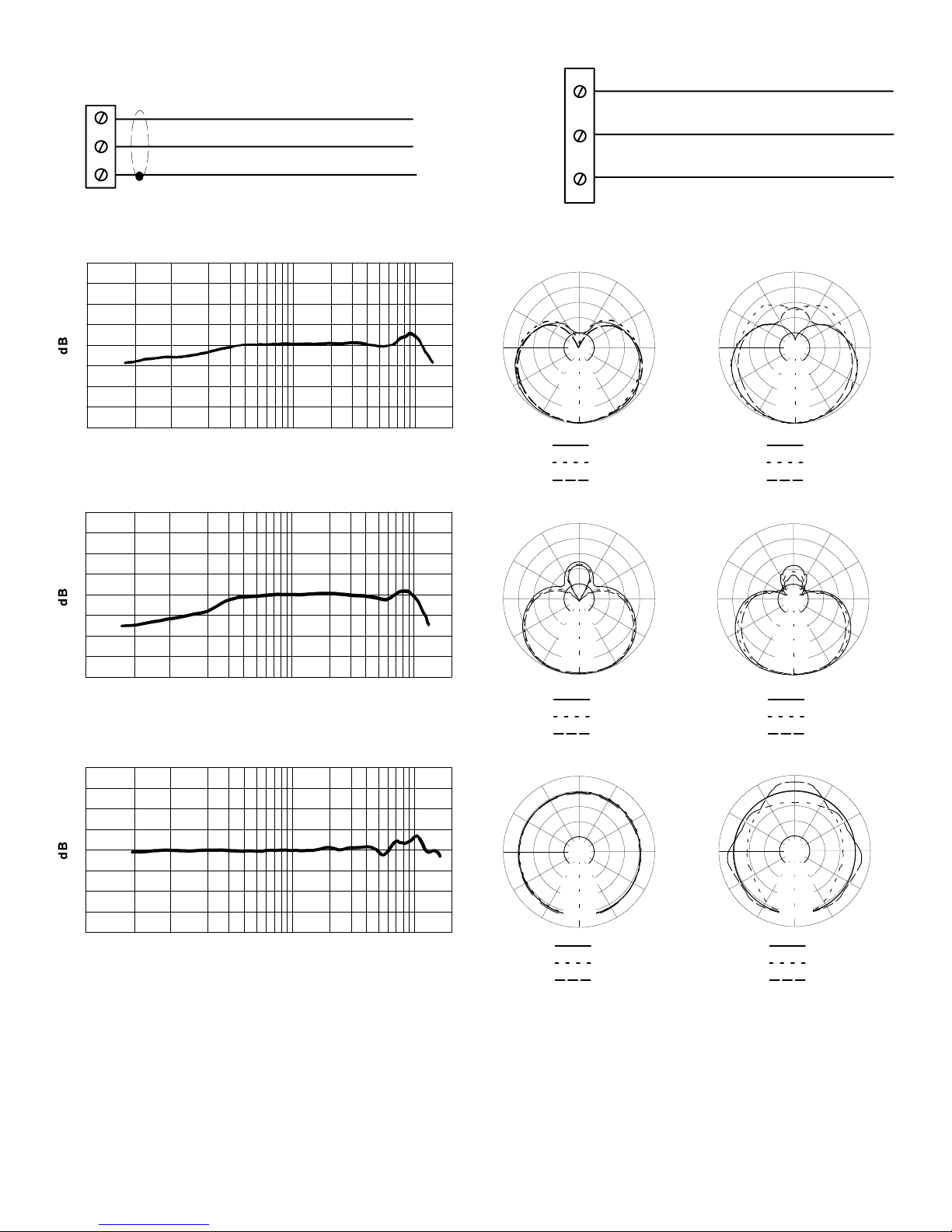
MIC OUT
SORTIE MICRO
MIKRO AUS
SALIDA DE MICROFONO
USCITA MICROFONO
–
+
LOGIC IN/OUT
BLACK
RED
SHIELD
LED IN
NOIR
ROUGE
BLINDAGE
SCHWARZ
ROT
ABSCHIRMUNG
NEGRO
ROJO
BLINDAJE
NERO
ROSSO
SCHERMATURA
ENTRÉEE DEL
LED EIN
ENTRADA DE LED
INGRESSO LED
SWITCH OUT
COUPURE
SCHALTER AUSCHALTER AUS
SALIDA DE INTERRUPTOR
USCITA INTERRUTTORE
LOGIC GND
MASSE LOGIQUE
LOGISCHE ERDE
TIERRA DE CIRCUITOS LOGICOS
MASSA LOGICA
ORANGE ORANGE
WHITE BLANC
GREEN
VERT
ORANGE NARANJA
WEISS
GRÜN
E/S LOGIQUE LOGIK EIN/AUS ENTRADAS/SALIDAS LOGICAS INGRESSO/USCITA LOGICI
FIGURE 6 • FIGURE 6 • ABBILDUNG6 • FIGURA 6 • FIGURA 6
o
180
150
o
150
o
150
BIANCA
BLANCA
VERDE
o
180
o
VERDE
ARANCIONE
o
150
+10
–10
+10
–10
o
120
20,000
20,000
o
90
–20 dB
150
150
–15 dB
–10 dB
–5 dB
o
30
30
0
250 Hz
500 Hz
1000 Hz
o
180
o
–20 dB
–15 dB
–10 dB
–5 dB
o
0
250 Hz
500 Hz
1000 Hz
o
180
o
o
60
o
120
o
90
o
60
0
50 100 20020
500 1,000 2,000 5,000 10,000
Hz
CARDIOID
CARDIOÏDE
KARDIOID
CARDIOIDE
CARDIOIDE
0
50 100 20020
500 1,000 2,000 5,000 10,000
Hz
SUPERCARDIOID
SUPERCARDIOÏDE
SUPERKARDIOID
SUPERCARDIOIDE
SUPERCARDIOIDE
o
120
90
o
60
o
30
CARDIOÏDE
KARDIOID
o
150
o
120
90
o
60
o
30
SUPERCARDIOID
SUPERCARDIOÏDE
SUPERKARDIOID
o
150
o
CARDIOID
CARDIOIDE
CARDIOIDE
o
90
SUPERCARDIOIDE
SUPERCARDIOIDE
o
120
o
90
–20 dB
150
30
150
–15 dB
–10 dB
–5 dB
o
30
0
2500 Hz
6400 Hz
10000 Hz
o
180
o
–20 dB
–15 dB
–10 dB
–5 dB
o
0
2500 Hz
6400 Hz
10000 Hz
o
180
o
o
60
o
120
o
o
60
o
120
o
90
o
60
o
30
o
150
o
120
o
90
o
60
o
30
o
150
+10
0
–10
500 1,000 2,000 5,000 10,00050 100 20020
Hz
OMNIDIRECTIONNELLE
ALLE RICHTUNGEN
OMNIDIRECTIONAL
OMNIDIRECCIONAL
OMNIDIREZIONALE
TYPICAL FREQUENCY RESPONSE
COURBE DE RÉPONSE TYPIQUE
TYPISCHER FREQUENZGANG
RESPUESTA DE FRECUENCIA TIPICA
RISPOSTA IN FREQUENZA TIPICA
FIGURE 7 • FIGURE 7 • ABBILDUNG 7 • FIGURA 7 • FIGURA 7
20,000
o
120
o
90
–20 dB
o
60
–15 dB
–10 dB
–5 dB
o
30
0
250 Hz
500 Hz
1000 Hz
OMNIDIRECTIONNELLE
ALLE RICHTUNGEN
o
120
o
90
o
60
o
30
OMNIDIRECTIONAL
o
120
o
90
o
60
o
30
OMNIDIRECCIONAL
OMNIDIREZIONALE
–20 dB
–15 dB
–10 dB
–5 dB
0
2500 Hz
6400 Hz
10000 Hz
TYPICAL POLAR PATTERNS
COURBES DE DIRECTIVITÉ TYPIQUES
TYPISCHE POLARMUSTER
PATRONES DE CAPTACION POLAR TIPICOS
DIAGRAMMI POLARI TIPICI
FIGURE 8 • FIGURE 8 • ABBILDUNG 8 • FIGURA 8 • FIGURA 8
22
o
120
o
90
o
60
o
30
Page 23
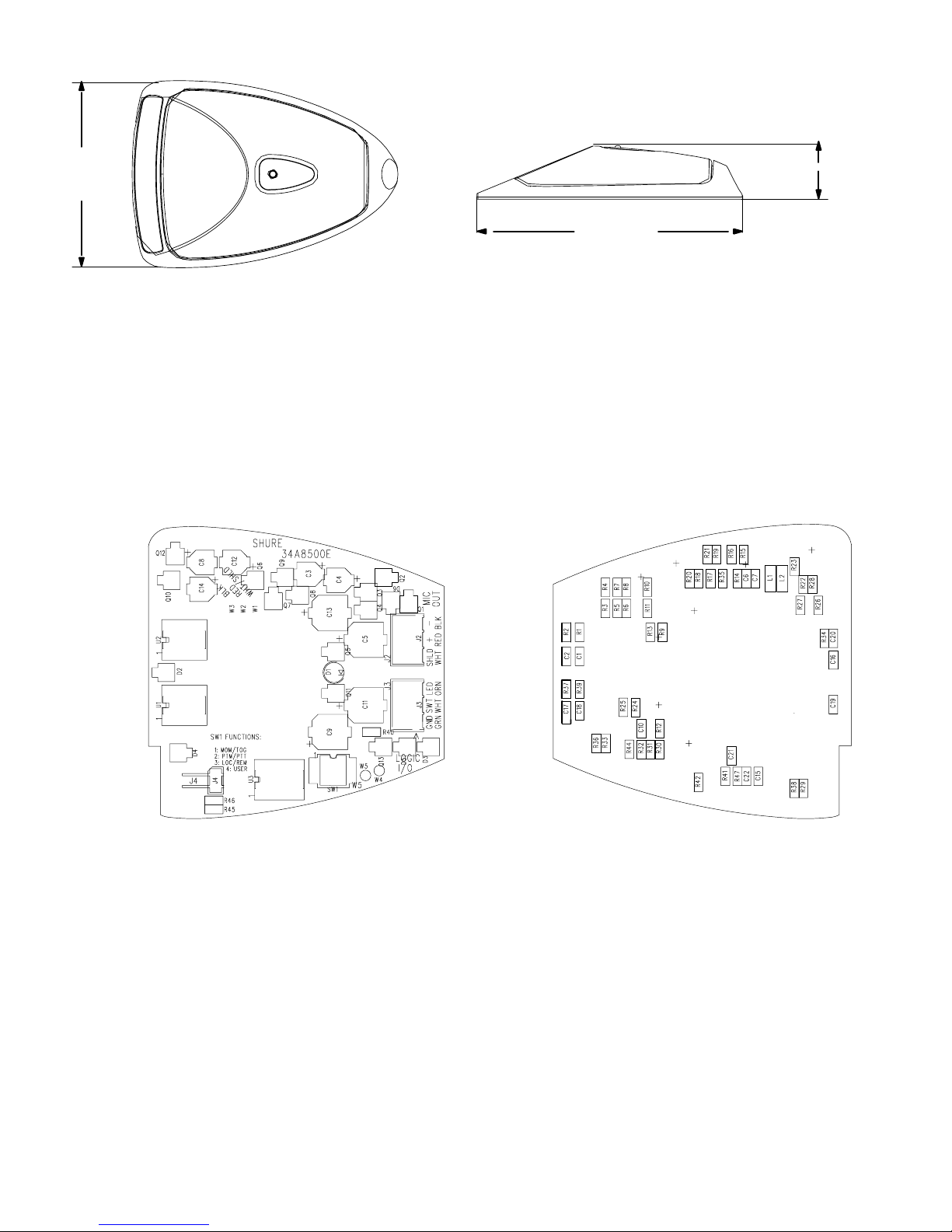
76.2 mm
(3 in.)
41.2 mm
(1.621 in.)
108.3 mm
(4.263 in.)
DIMENSIONS
DIMENSIONS
ABMESSUNGEN
DIMENSIONES
DIMENSIONI
FIGURE 9 • FIGURE 9 • ABBILDUNG 9 • FIGURA 9 • FIGURA 9
SIDE 1 CÔTÉ 1 SEITE 1 LADO 1 LATO 1 SIDE 2 CÔTÉ 2 SEITE 2 LADO 2 LATO 2
LEYENDA DE TARJETA DE CIRCUITOS DE MX392/MX393
LEGENDA DELLA SCHEDA DI CIRCUITI DEI MODELLI MX392/MX393
FIGURE 10 • FIGURE 10 • ABBILDUNG10 • FIGURA 10 • FIGURA 10
MX392/MX393 CIRCUIT BOARD LEGEND
LÉGENDE DU CIRCUIT IMPRIMÉ MX392/MX393
BESCHRIFTUNG DER MX392/MX393 LEITERPLATTE
23
Page 24
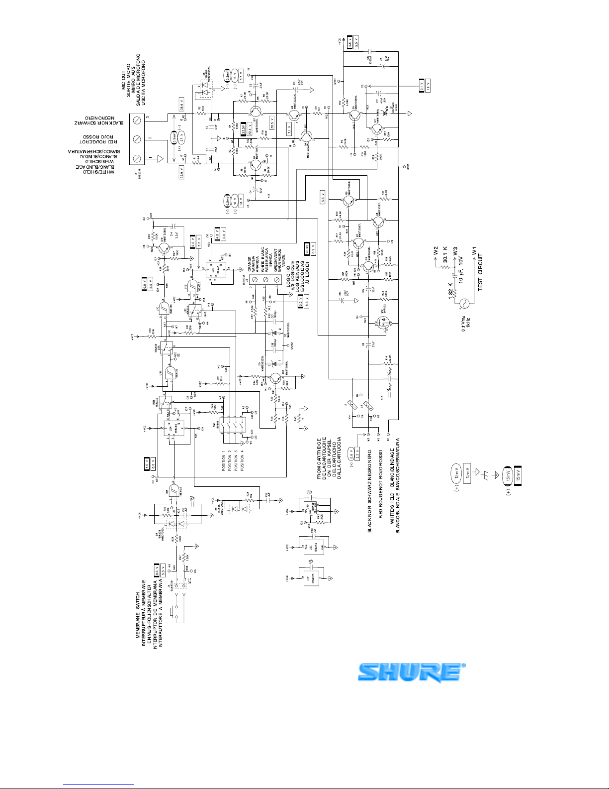
MX392/MX393 SCHEMATIC DIAGRAM
SCHEMA DE PRINCIPE MX392/MX393
STROMLAUFPLAN FUR MX392/MX393
DIAGRAMA ESQUEMATICO DEL MX392/MX393
SCHEMA CIRCUITALE DEI MODELLI MX392/MX393
FIGURE 11FIGURE 11ABBILDUNG 11FIGURA 11FIGURA 11
24
in µF, ±10%, and 50V or more unless otherwise specified.
= DC Voltage
= Printed Circuit Ground
= Case Ground
= Logic Ground
= AC Voltage, Mic Muted (J4 Shorted)
= DC Voltage, Mic Muted (J4 Shorted)
(+) and/or (–) indicate AC polarity relative to input test signal.
NOTES;
1. All resistors 1/10W, ±1%, 0805, unless otherwise specified.
2. Electrolytic capacitors shown in µF x Volts. All non–polar capacitors
3. = AC Voltage
4. Connect J2 to mic input of a Shure M367 Mixer or equivalent, with
SHURE Incorporated Web Address: http://www.shure.com
222 Hartrey Avenue, Evanston, IL 60202–3696, U.S.A.
Phone: 847-866–2200 Fax: 847-866-2279
In Europe, Phone: 49-7131-72140 Fax: 49-7131-721414
In Asia, Phone: 852-2893-4290 Fax: 852-2893-4055
Elsewhere, Phone: 847-866–2200 Fax: 847-866-2585
48V phantom power switched on.
 Loading...