

Shure Microflex MX400 Series User Manual

MX400 Series -- Gooseneck Microphones
General Description
Shure Microflex MX400S Series microphones are miniature gooseneck-mounted electret condenser micro-
phones designed primarily for speech and vocal pickup. They can be mounted on lecterns, pulpits, or conference
tables. All models include a preamplifier and are available with interchangeable cardioid, supercardioid, or omnidi-
rectional cartridges.
MX400 microphones are available with 305 mm (12 in.) or 457 mm (18 in.) goosenecks, with or without a mute
switch. They are available in supercardioid, cardioid and omnidirectional polar patterns.
• "S" models include a mute button and LED.
• "D" models include a desktop base with programmable mute button and LED and logic input and output.
• "SE" models feature a surface mount flange with side-exit cable.
The polar pattern of the included cartridge is indicated by a model number suffix:
/C Cardioid
/S Supercardioid
/O Omnidirectional
/N Cartridge not included
®
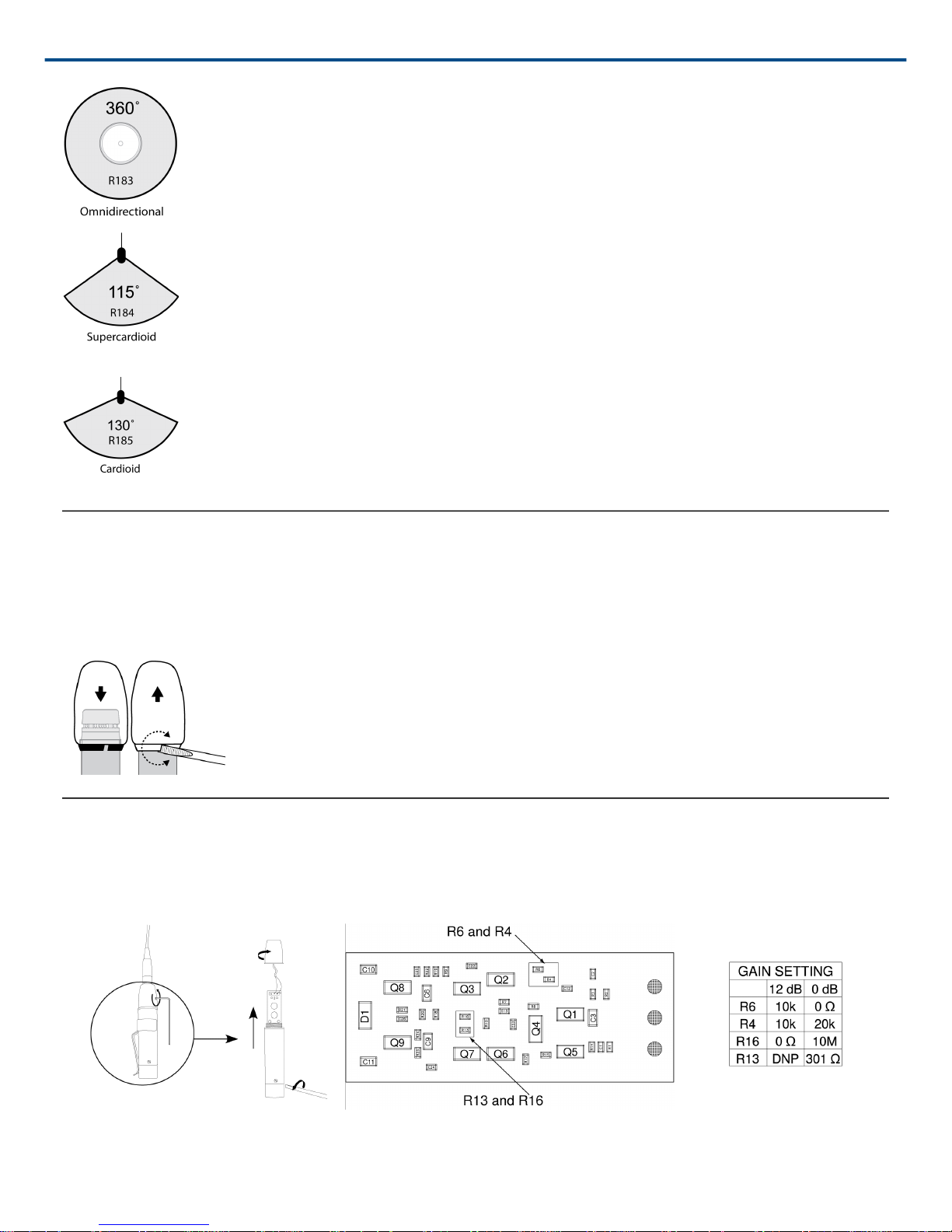
Interchangeable Cartridges
Microflex microphones use interchangeable cartridges that allow you to choose the polar pattern for different in-
stallations.
1/10
Shure Incorporated
Snap-Fit Windscreen
• Snap into the groove below the cartridge.
• To remove, spread the gap with a screwdriver or thumbnail.
• Provides 30 dB of "pop" protection.
Preamp Gain
If necessary, the preamplifier gain can be reduced by 12 dB. Contact an authorized Shure service center for infor-
mation.
2/10
Shure Incorporated
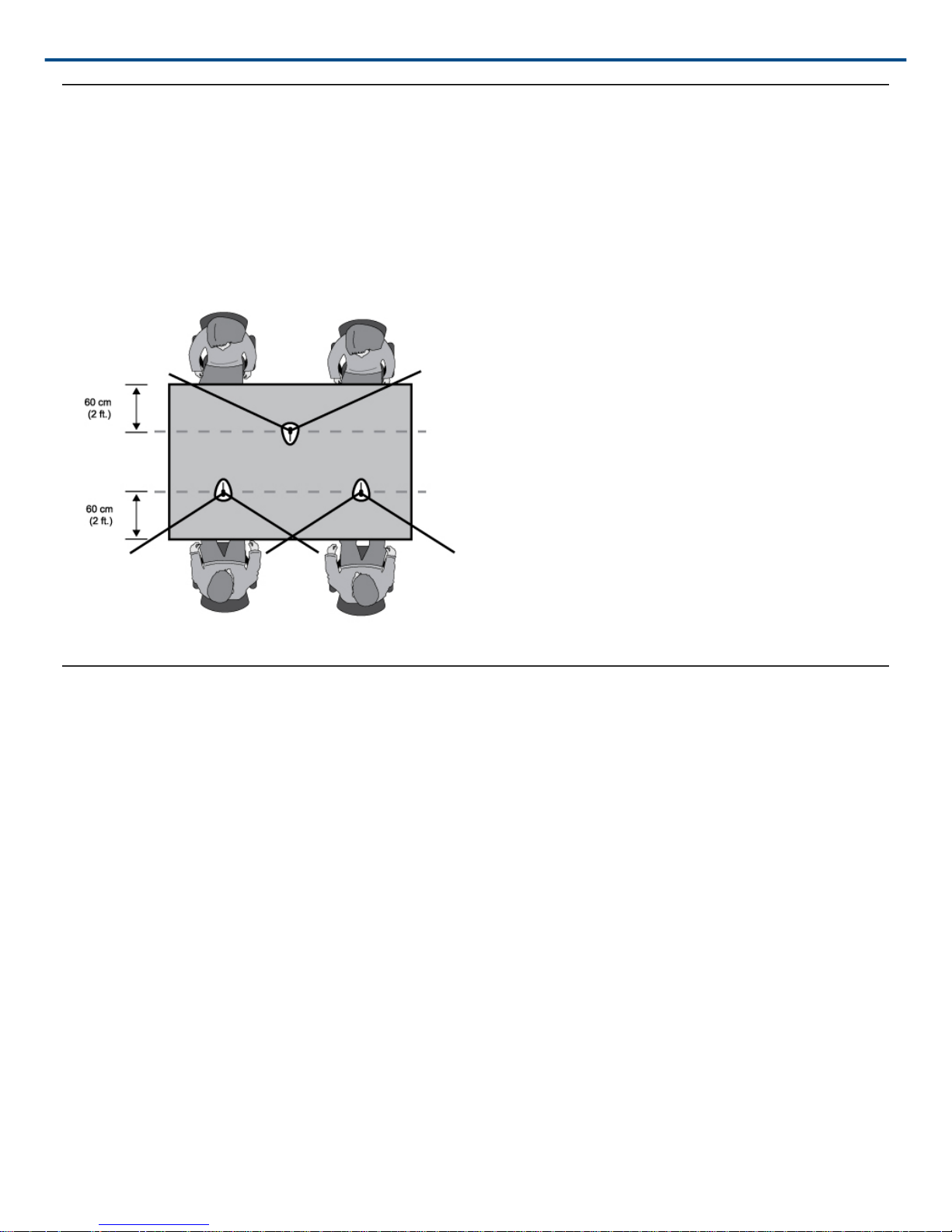
Microphone Placement
• Aim the microphone toward the desired source, such as the talker.
• Aim it away from any unwanted source, such as a loudspeaker.
• Place the microphone within 15 to 30cm (6 to 12 in.) of the desired sound source.
• Always use the supplied windscreen or optional metal windscreen to control breath noise.
• If four or more microphones will be open at the same time, use of an automatic mixer, such as the Shure
SCM810 or SCM410, is recommended.
Permanent Installation
Mount the microphone using one of the following methods.
Flange
1. Drill a 22 mm (7/8 in.) diameter hole in the desired location.
2. Trace and drill three starter holes for the supplied screws using the flange as a template.
3. Insert the preamplifier through the mounting flange.
4. Slip the mounting flange retaining ring over the bottom of the preamplifier and slide it up until it is flush to the
bottom of the flange. Then press the ring firmly into place.
5. Secure the flange to the mounting surface with three screws.
3/10
 Loading...