

Shure Microflex MX391 Series, Microflex MX391W, Microflex MX391LP, Microflex MX391WLP User Manual
Microflex MX391 Series
Boundary Microphone s User Guide
MICROFLEX MX391 SERIES
BOUNDARY MICROPHONES
GENERAL
Shure Microflex MX391 Series microphones are small, surfacemounted electret condenser microphones designed for mounting on
conference tables, s tage floors, and l ecterns. Their high s ensitivity a nd
wide frequency range make them especially suitable for picking up
speech and vocals i n s ound r einforcem ent a nd r ecording applications.
FEATURES
Flat frequency response across the vocal range for uncolored
sound
Interchangeable cardioid, supercardioid, and omnidirectional
cartridges that provide optimal choice for each application
Sleek, low-profile design for unobtrusive appearance
Balanced, transformerless output f or increased immunity to n oise
over long cable runs
MODEL VARIA TIONS
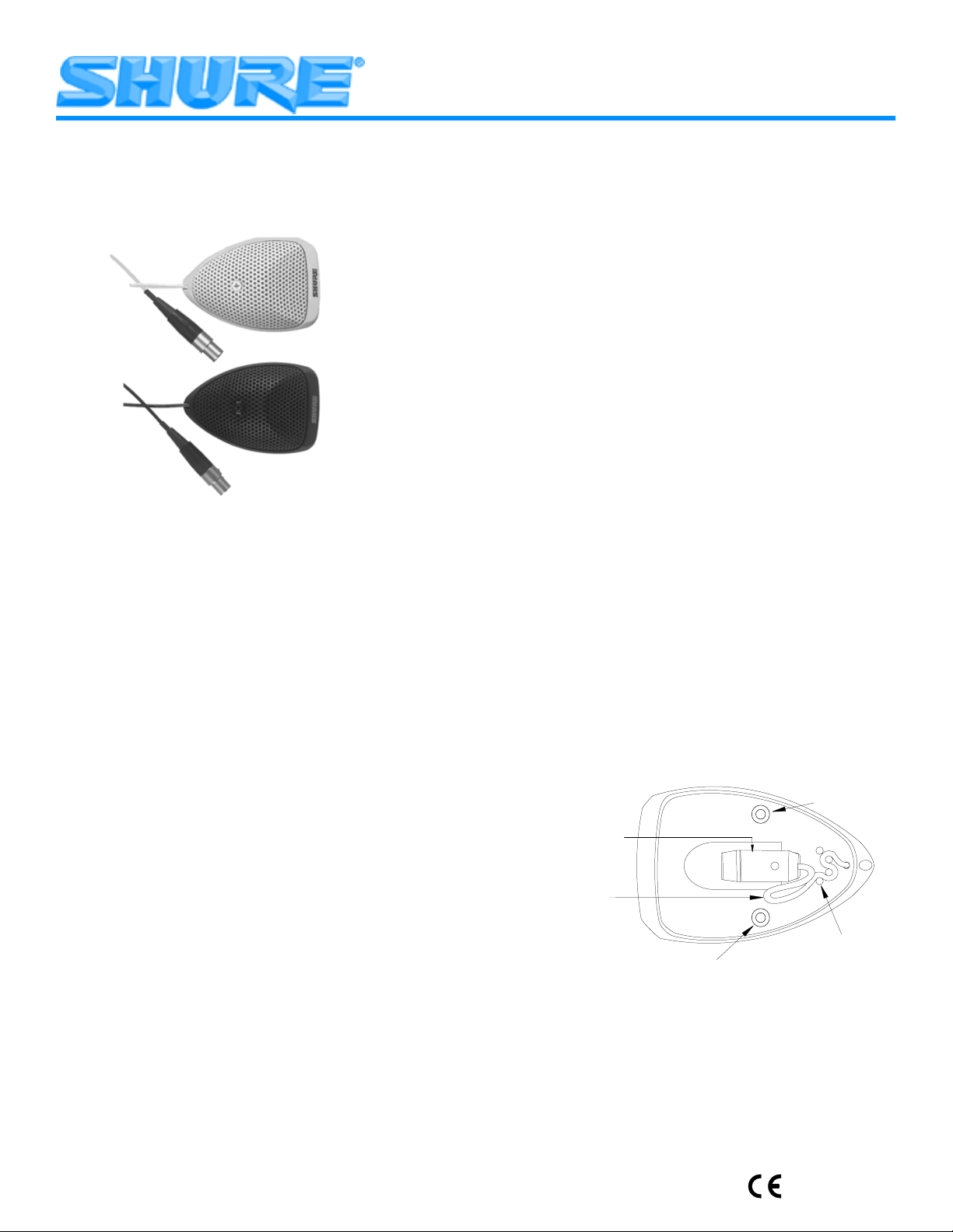
MX391 and MX391W (white) m odels have a n a ttached 4 m eter ( 12
ft) cable terminated with a 4–pin m ini c onnector a nd a separate preamplifier. A r ubber st rain relief is p rovided for applications where y ou
want to remove the 4–pin mini connector and connect the microphone cable directly to screw terminals in the preamplifier.
MX391LP and MX391WLP (white) models have an attached 4
meter ( 12 ft) cable terminated with a 4–pin mini connector, but do not
include a p reamplifier. I nstead, t he microphone can b e c onnected directly to a Shure wireless body-pack transmitter.
Microflex
changeable cartridges, a s i ndicated b y t he m odel number ( found o n t he
bottom of the microphone base).
MX391/C series. Cardioid pickup pattern for general sound rein-
forcement applications. Pickup angle (–3 dB) = 130°.
MX391/S s eries. Supercardioid pickup pattern f or sound r ein forcement applications requiring narrow or more distant coverage. Pickup angle (–3 dB) = 115°.
MX391/O series. Omnidirectional pickup pattern for recording or
remote monitoring applications. Pickup angle = 360°.
boundary microphones come with one of three inter-
PERMANENT INSTALLATION
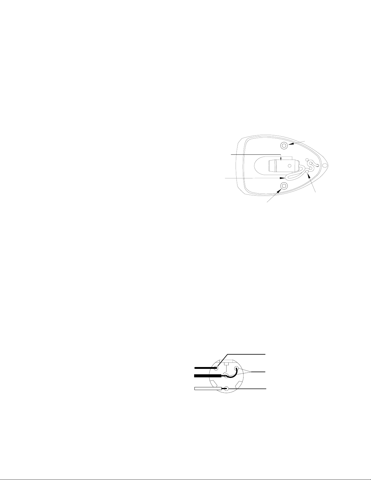
Screw holes in the microphone base and a bottom exit hole for the
microphone cable are provided for permanent installation of the
boundary microphone. To re-route the microphone cable through
the bottom exit hole, use the following steps (Figure 1):
1. Remove the grille from the microphone base by loosening the
single screw on top of the grille.
2. Remove the 4–pin mini connector from the end of the cable by
cutting the cable just below the connector.
WARNING: Do not attempt to detach the cable from the micro-
phone interface.
3. Secure the cable with your thumb or finger so that it does not
come loose from the strain-relief posts as you thread the cable
out from the rear exit hole.
4. Re-route the cable through the bottom exit hole and pull snug.
IMPORTANT: Be sure the cable is pressed firmly down between the strain relief posts before replacing the grill.
5. Set the grille back into place and thread the screw through the
perforated metal grille and into the microphone interface and
tighten.
6. Use the supplied template (Figure 3) to drill screw holes and a
bottom exit hole in the mounting surface.
7. After threading the cable through the bottom exit hole in the
mounting surface, either re-attach the 4–pin mini connector
(Figure 2) or wire the cable to the screw terminals in the preamplifier (use the supplied rubber strain relief to secure the connection).
NOTE: For detailed instructions on re-attaching the 4–pin mini
connector, contact the Shure Applications Group.
REPAINTING THE MX391 SERIES
Before applying paint to the MX391 series, remove the grille from
the base, remove the foam from the inside of the grill, and mask the
microphone cartridge and interface. Also mask the cable where
necessary.
Screw Hole
Microphone Interface
Service Loop
Strain Relief Post
Screw Hole
RE-ROUTING THE CABLE
FIGURE 1
ADJUSTING PREAMP GAIN (Figure 4)
This MX m icrophone i ncludes a n a djustable g ain p reamplifier, allowing the user to specify a 12 d B o r 0 d B g ain s etting. T he pream p s hips
at the 12dB setting. Gain may be decreased by 12dB by moving the
preamp jumpers to the 0dB setting.
2002, Shure Incorporated
27C3027 (BE)
Printed in U.S.A.
MICROPHONE SPECIFICATIONS
Polar Pattern (Figure 6)
Cardioid (MX391/C, MX391W/C, MX391LP/C, MX391WLP/C)
Supercardioid (MX391/S, MX391W/S, MX391LP/S,
MX391WLP/S)
Omnidirectional (MX391/O, MX391W/O, MX391LP/O,
MX391WLP/O)
Environmental Requirements
Operating Temperature Range: –18° C to 57° C (0° F to 135° F)
Relative Humidity: 0 to 95%
Dimensions
See Figure 3
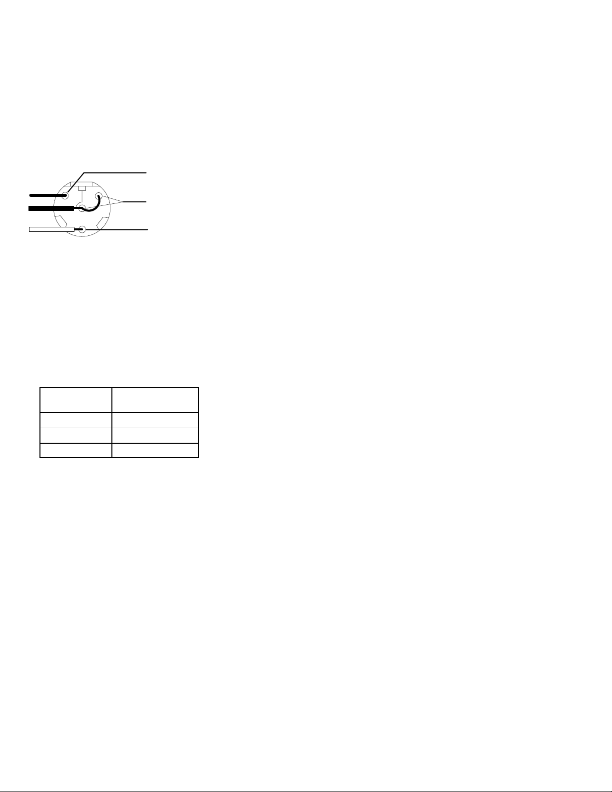
Wiring Diagram
PIN 1 = SHIELD (use only HALF of the
shield, the other half solder to cable
3
1
4
2
PINS 3 and 4 = BLACK LEAD (jumped)
clamp)
PIN 2 = RED LEAD
FIGURE 2
PREAMPLIFIER SPECIFICATIONS
These specifications apply only to the MX391/MX391W microphones when used with the supplied preamplifier. All measurements
taken with the microphone mounted on a 76.2 cm x 76.2 cm (30 in.
x 30 in.) wooden surface and with the sound source incident at 30°
with respect to the surface plane.
Frequency Response (Figure 5)
50 to 17,000 Hz
Output Impedance (at 1000 Hz)
180Ω actual (rated at 150Ω)
Open Circuit Sensitivity
Cartridge Type
Cardioid –29.6 dB (33.5 mV)
Supercardioid –28.3 dB (38.5 mV)
Omnidirectional –21.5 dB (81.4 mV)
All settings –12 dB at 0 gain
*1 Pascal = 94 dB SPL
1 kHz ref. 1 V per
Pascal *
Maximum Sound Pressure Level
(1 kHz at 1% Total Harmonic Distortion, 1 kΩ load)
Cardioid: 118.8 dB
Supercardioid: 117.5 dB
Omnidirectional: 110.7 dB
All settings +6 dB at 0 gain
Signal to Noise Ratio (referenced at 94 dB SPL)
Cardioid: 71.4 dB
Supercardioid: 72.7 dB
Omnidirectional: 79.5 dB
Equivalent Output Noise (A-weighted)
Cardioid: 22.6 dB SPL
Supercardioid: 21.3 dB SPL
Omnidirectional: 14.5 dB SPL
Dynamic Range
at 1 kΩ Load
96.2 dB
100 dB at 0 gain
Common Mode Rejection
45 dB minimum, 10 Hz to 100 kHz
Preamplifier Output Clipping Level
–6 dBV (0.5 V)
–12 dB at 0 gain
Polarity
Positive sound pressure on diaphragm produces positive voltage
on pin 2 relative to pin 3 of the preamplifier XLR output connector.
Power Requirements
11 to 52 Vdc phantom
2.0 mA current consumption
Certification
Eligible to bear CE Marking. Conforms to European EMC
Directive 89/336/EEC. Meets applicable tests and performance
criteria in European Standard EN55103 (1996) parts 1 and 2, for
residential (E1) and light industrial (E2) environments.
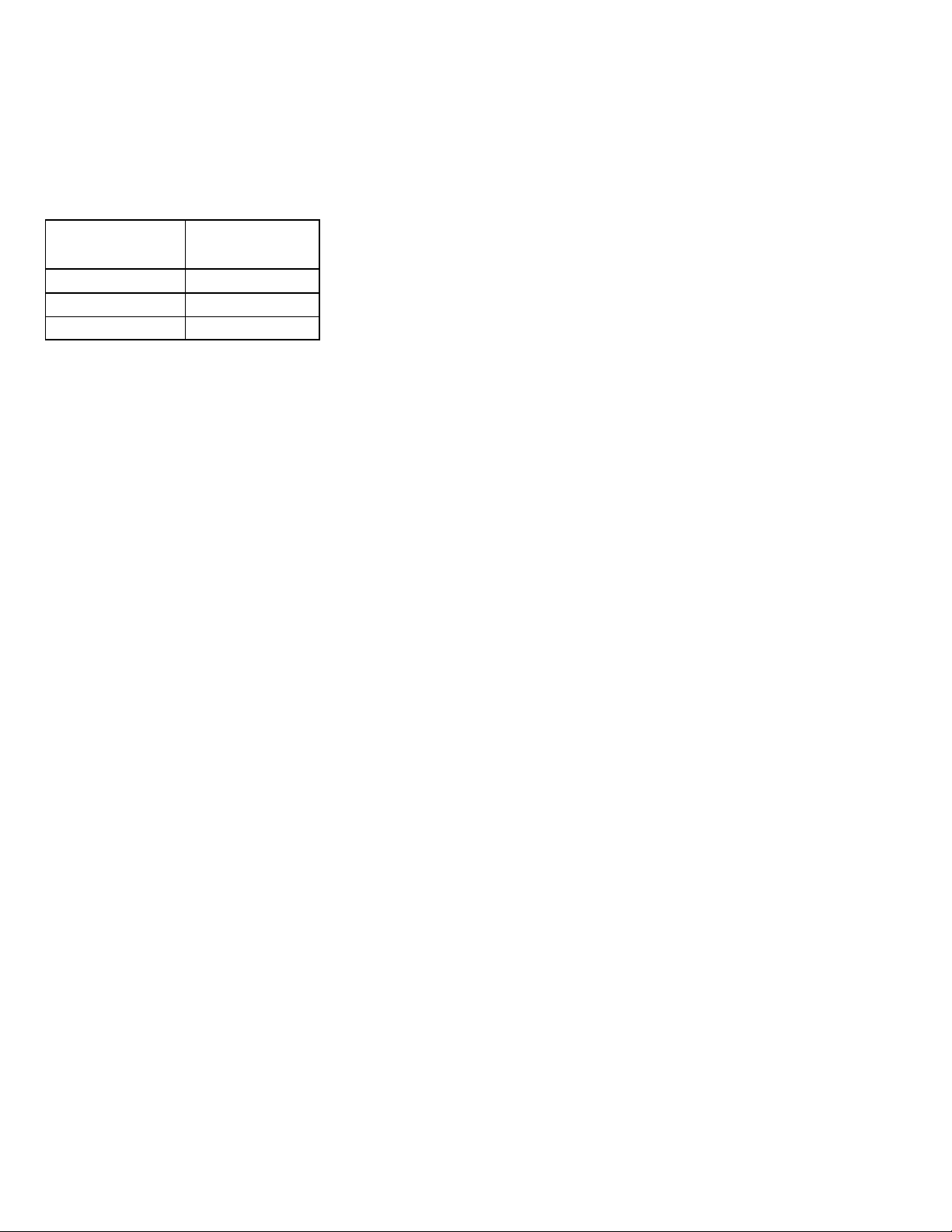
REPLACEMENT PARTS
Omnidirectional Cartridge R183B. . . . . . . . . . . . . . . . . . . . . . . . . .
Supercardioid Cartridge R184B. . . . . . . . . . . . . . . . . . . . . . . . . . .
Cardioid Cartridge R185B. . . . . . . . . . . . . . . . . . . . . . . . . . . . . . . .
Preamplifier Kit RK183PK. . . . . . . . . . . . . . . . . . . . . . . . . . . . . . . .
Replacement Cable Kit (black) C123. . . . . . . . . . . . . . . . . . . . . .
Replacement Cable Kit (white) C125. . . . . . . . . . . . . . . . . . . . . .
NOTE: For technical data by Fax, phone 1-800-488-3297 and follow
the recorded instructions. For additional technical assistance, phone
Shure at (847) 866-2200. In Europe, phone 49-7131-72140.
SHURE, the Shure logo, and MICROFLEX are registered trademarks
of Shure Incorporated.
2
GÉNÉRALITÉS
Les Shure Microflex série MX391 sont des petits microphones
électrostatiques à électrets à montage en surface conçus pour les
tables de conférence, planchers de scène et lutrins. Grâce à leur
haute sensibilité et vaste gamme de fréquences, ils sont particulièrement indiqués pour le captage de la voix lors de l’amplification
en direct ou des enregistrements.
AVANTAGES
Courbe de réponse plate dans toute la gamme vocale pour un
son non coloré
Cartouches cardioïde, supercardioïde e t om idirectionnelle inter-
changeables perm ettant l ’adaptation optim ale à c haque s ituation
Extra–plat et profilé pour un aspect discret
Sortie équilibrée sans transformateur pour une immunité au
bruit accrue avec de grandes longueurs de câble
Variantes
Les modèles MX391 et MX391W (blanc) sont dotés d’un câble
fixé de 4 mètres (12 pi) avec connecteur miniature 4–broches et d’un
préamplificateur séparé. Le connecteur miniature 4–broches peut
être retiré pour brancher le câble du microphone directement sur les
bornes du préamplificateur. Un soulagement de traction en caoutchouc est fourni pour ce type de montage.
Les modèles MX391LP et MX391WLP (blanc) sont dotés d’un
câble fixé de 4 mètres (12 pi) avec connecteur miniature 4–broches
à quatre broches mais ne sont pas équipés d’un préamplificateur. À
la place, le microphone peut être relié directement à un transmetteur
de poche sans fil Shure.
Les microphones périphériques Microflex
sont fournis avec
l’une de trois cartouches interchangeables, dont le type est indiqué
par le numéro de modèle (sur le dessous de la base du microphone).
Serie MX391/C. Configuration cardioïde pour la sonorisation gé-
nérale. Angle de captage (–3 dB) = 130°.
Serie MX391/S. Configuration supercardioïde pour les applica-
tions exigeant un captage étroit ou à plus grande distance. Angle de
captage (–3 dB) = 115°.
Serie MX391/O. Configuration omnidirectionnelle pour l’enre-
gistrement ou les applications de contrôle à distance. Angle de captage = 360°.
INSTALLATION PERMANENTE
Des trous de vis dans la base du microphone et un trou de sortie
par le bas pour le câble sont prévus pour l’installation permanente
du microphone périphérique. Pour acheminer le câble du microphone par le trou du bas, procéder comme suit (Figure 1):
1. Retirer la grille de la base du microphone en desserrant la vis
unique du dessus.
2. Retirer le connecteur miniature 4–broches en coupant le câble
juste au–dessous du connecteur.
AVERTISSEMENT : Ne pas essayer de détacher le câble de
l’interface du microphone.
3. Maintenir le câble avec le pouce ou le doigt de façon à ce qu’il
ne s’échappe pas des goujons de soulagement de traction
lorsqu’il est sorti du trou arrière.
4. Réacheminer le câble dans le trou de sortie du dessous et le ti-
rer fermement.
IMPORTANT : S’assurer que le câble est bien serré entre les
goujons de soulagement de traction avant de remettre la grille
en place.
5. Remettre la grille en métal perforé en place et insérer la vis dans
cette grille et l’interface du microphone et la serrer.
6. Utiliser le gabarit fourni (Figure 3) pour le perçage des trous de
vis et du trou de sortie par le bas du câble dans la surface de
montage.
7. Une fois le câble passé dans le trou de sortie par le bas de la
surface de montage, soit remonter le connecteur miniature
4–broches (Figure 2), soit brancher le câble sur les bornes à vis
du préamplificateur (utiliser le soulagement de tension en
caoutchouc pour assujettir le branchement).
REMARQUE : Pour des instructions détaillées sur le remon-
tage du connecteur miniature 4–broches, contacter le Groupe
d’applications Shure.
PEINTURE DU SERIE MX391
Avant de peindre le serie MX391, retirer la grille de la base, enlever la mousse de l’intérieur de la grille et masquer la cartouche et l’interface du microphone. Masquer également le câble selon le besoin.
Trou de vis
Interface du
microphone
Boucle de
relaxation
Goujon de
Trou de vis
RÉACHEMINEMENT DU CÂBLE
soulagement de
traction
FIGURE 1
RÉGLAGE DU GAIN DU PRÉAMPLI (Figure 4)
Ce microphone MX comprend un préamplificateur à gain ré-
glable, ce qui permet à l ’utilisateur de choisir un réglage d u g ain
de 12 dB ou de 0 dB. Le préampli est livré avec le réglage à 12
dB. Le gain peut être diminué de 12 dB en déplaçant l es cava-
liers du préampli sur le réglage à 0 dB.
CARACTÉRISTIQUES DU MICROPHONE
Courbe de directivité (Figure 6)
Cardioïde (MX391/C, MX391W/C, MX391LP/C, MX381LPW/C)
Supercardioïde (MX391/S, MX391W/S, MX391LP/S, MX391WLP/S)
Omnidirectionnelle (MX391/O, MX391W/O, MX391LP/O,
MX391WLP/O)
Conditions environnementales
Plage de températures de fonctionnement : –18 à 57 °C
(0 à 135 °F)
Humidité relative : 0 à 95 %
Dimensions
Voir la Figure 3
Schéma de câblage
BROCHE 1 = BLINDAGE (n’utilise que
la moitié du blindage, l’autre moitié se
3
1
4
2
soudant sur la bride du câble)
BROCHES 3 et 4 = FIL NOIR (ponté)
BROCHE 2 = FIL ROUGE
FIGURE 2
3
CARACTÉRISTIQUES DU PRÉAMPLIFICATEUR
Ces caractéristiques ne s’appliquent qu’au microphone MX391
lorsqu’il est utilisé avec le préamplificateur fourni. Toutes les mesures ont été prises avec le microphone monté sur une surface en
bois de 76,2 x 76,2 cm (30 x 30 po).
Courbe de réponse (Figure 5)
50 à 17 000 Hz
Impédance de sortie (1000 Hz)
180 Ω réelle (nominal, 150 Ω)
Sensibilité en circuit ouvert
Type de cartouche
Réf. 1 kHz, 1 V par
Pascal *
Cardioïde –29,6 dB (33,5 mV)
Supercardioïde –28,3 dB (38,5 mV)
Omnidirectionnelle –21,5 dB (81,4 mV)
Toutes les configurations –12 dB à 0 gain
*1 Pascal = 94 dB NPA
Pression acoustique maximum
(1 kHz avec 1 % de distorsion harmonique totale et charge de
1 kΩ)
Cardioïde : 118,8 dB
Supercardioïde : 117,5 dB
Omnidirectionnelle : 110,7 dB
+6 dB à 0 gain
Rapport signal/bruit (mesuré avec une pression acoustique de
94 dB NPA)
Cardioïde : 71,4 dB
Supercardioïde : 72,7 dB
Omnidirectionnelle : 79,5 dB
Bruit de sortie équivalent (pondéré en A)
Cardioïde : 22,6 dB NPA
Supercardioïde : 21,3 dB NPA
Omnidirectionnelle : 14,5 dB NPA
Gamme dynamique
vec charge de 1 kW
96,2 dB
100 dB à 0 gain
Rejet en mode commun
45 dB minimum, 10 Hz à 100 kHz
Niveau d’écrêtage de sortie du préamplificateur
–6 dBV (0,5 V)
–12 dB à 0 gain
Polarité
Une pression acoustique positive sur le diaphragme produit une
tension positive sur la broche 2 par rapport à la broche 3 du
connecteur de sortie.
Alimentation
11 à 52 V c.c. duplex
Consommation de courant : 2,0 mA
Homologation
Autorisé à porter la marque CE. Conforme à la directive CEM
européenne 89/336/CEE. Conforme aux critères applicables de
test et de performances de la norme européenne EN 55103
(1996) parties 1 et 2 pour les environnements résidentiels (E1) et
d’industrie légère (E2).
PIÈCES DE RECHANGE
Cartouche omnidirectionnelle R183B. . . . . . . . . . . . . . . . . . . . . .
Cartouche supercardioïde R184B. . . . . . . . . . . . . . . . . . . . . . . . .
Cartouche cardioïde R185B. . . . . . . . . . . . . . . . . . . . . . . . . . . . . .
Kit de préamplificateur RK183PK. . . . . . . . . . . . . . . . . . . . . . . . .
Kit de câble de rechange (noir) C123. . . . . . . . . . . . . . . . . . . . . .
Kit de câble de rechange (blanc) C125. . . . . . . . . . . . . . . . . . . .
REMARQUE : Pour toute information technique par télécopie, compos-
er le 1–800–488–3297 et suivre les instructions de l’enregistrement.
Pour toute assistance technique supplémentaire, appeler Shure au
(847) 866–2200. En Europe, appeler le 49–7131–72140.
ALLGEMEINES
Shure Microflex Mikrofone der Reihe MX391 sind kleine oberflächenmontierte Elektretkondensatormikrofone, die zur Anbringung an Konferenztischen, Bühnenböden und Vortragspulten vorgesehen sind. Durch ihre hohe Empfindlichkeit und den breiten Frequenzbereich eignen sie sich besonders zur Aufnahme von
Sprache und Gesang bei der Tonverstärkung und bei Aufzeichnungsanwendungen.
MERKMALE
Ebener Frequenzgang über den gesamten Stimmbereich für
unverfärbten Klang
Austauschbare Nieren–, Supernieren– und Kugelkapseln, die
optimale Ausrüstung für jede Anwendung ermöglichen
Glattes Flachformdesign für unauffälliges Erscheinungsbild
Symmetrischer transformatorloser Ausgang für gesteigerte
Rauschunempfindlichkeit bei langen Kabelführungen
MODELLVARIANTEN
An den MX391 und MX391W (weiß) –Modellen ist ein 4 Meter
langes Kabel angebracht, das mit einem 4–pin miniatur steckverbindung abgeschlossen ist; sie verfügen außerdem über einen separaten V orverstärker. Auf Wunsch kann der 4–pin miniatur steckverbindung entfernt und das Mikrofonkabel direkt an den Schraubklemmen am Vorverstärker angeschlossen werden. Für dieses Anschlußverfahren wird eine Gummizugentlastung mitgeliefert.
An den MX391LP und MX391WLP (weiß)–Modellen ist ein 4 Meter langes Kabel angebracht, das mit einem 4–pin miniatur steckverbindung abgeschlossen ist; sie verfügen allerdings über keinen V orverstärker. Stattdessen kann das Mikrofon direkt an einen drahtlosen, am Körper getragenen Shure-Sender angeschlossen werden.
Microflex
-Grenzflächenmikrofone werden mit einer der folgenden drei austauschbaren Kapseln geliefert. Die Modellnummer (an
der Unterseite des Mikrofonsockels) gibt an, um welche Ausführung
es sich bei dem Mikrofon handelt.
Der Reihe MX391/C. Nierenrichtcharakteristik für allgemeine
Tonverstärkungsanwendungen. Ansprechwinkel (–3 dB) = 130°.
Der Reihe MX391/S. Supernierenrichtcharakteristik für Ton-
verstärkungsanwendungen, die eine engere oder weiter entfernte
Abdeckung erfordern. Ansprechwinkel (–3 dB) = 115°.
Der Reihe MX391/O. Kugelrichtcharakteristik für Aufzeich-
nungs– oder Fernüberwachungsanwendungen. Ansprechwinkel =
360°.
DAUERHAFTE ANBRINGUNG
Zur dauerhaften Anbringung des Grenzflächenmikrofons sind
Schraubenbohrungen im Mikrofonsockel sowie eine Austrittsöffnung für das Mikrofonkabel an der Unterseite vorgesehen.
Um das Mikrofonkabel durch die Austrittsöffnung an der Unterseite
zu verlegen, sind die folgenden Schritte auszuführen (Abbildung 1):
1. Den Grill vom Mikrofonsockel abnehmen, indem die Schraube
an der Oberseite des Grills gelöst wird.
2. Den 4–pin miniatur steckverbindung vom Kabelende entfernen,
indem das Kabel unmittelbar vor dem Steckverbinder durchgeschnitten wird.
ACHTUNG: Nicht versuchen, das Kabel von der Mikrofonschnittstelle abzunehmen.
3. Das Kabel mit dem Daumen oder einem Finger festhalten, so
daß es sich nicht von den Zugentlastungsstiften löst, während
das Kabel durch die Austrittsöffnung an der Rückseite nach au-
ßen geführt wird.
4. Das Kabel durch die Austrittsöffnung an der Unterseite verle-
gen und straffziehen:
4
 Loading...