

Shure Microflex MX391 Series, Microflex MX391W, Microflex MX391LP, Microflex MX391WLP User Manual [en, de, es, it, fr]
Page 1
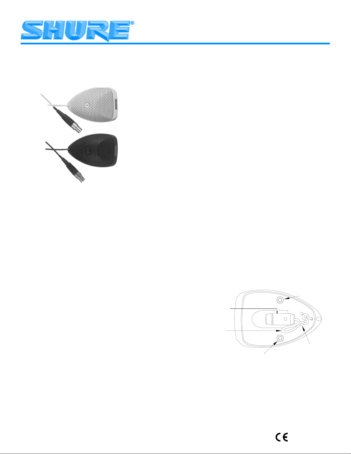
Microflex MX391 Series
Boundary Microphone s User Guide
MICROFLEX MX391 SERIES
BOUNDARY MICROPHONES
GENERAL
Shure Microflex MX391 Series microphones are small, surfacemounted electret condenser microphones designed for mounting on
conference tables, s tage floors, and l ecterns. Their high s ensitivity a nd
wide frequency range make them especially suitable for picking up
speech and vocals i n s ound r einforcem ent a nd r ecording applications.
FEATURES
Flat frequency response across the vocal range for uncolored
sound
Interchangeable cardioid, supercardioid, and omnidirectional
cartridges that provide optimal choice for each application
Sleek, low-profile design for unobtrusive appearance
Balanced, transformerless output f or increased immunity to n oise
over long cable runs
MODEL VARIA TIONS
MX391 and MX391W (white) m odels have a n a ttached 4 m eter ( 12
ft) cable terminated with a 4–pin m ini c onnector a nd a separate preamplifier. A r ubber st rain relief is p rovided for applications where y ou
want to remove the 4–pin mini connector and connect the microphone cable directly to screw terminals in the preamplifier.
MX391LP and MX391WLP (white) models have an attached 4
meter ( 12 ft) cable terminated with a 4–pin mini connector, but do not
include a p reamplifier. I nstead, t he microphone can b e c onnected directly to a Shure wireless body-pack transmitter.
Microflex
changeable cartridges, a s i ndicated b y t he m odel number ( found o n t he
bottom of the microphone base).
MX391/C series. Cardioid pickup pattern for general sound rein-
forcement applications. Pickup angle (–3 dB) = 130°.
MX391/S s eries. Supercardioid pickup pattern f or sound r ein forcement applications requiring narrow or more distant coverage. Pickup angle (–3 dB) = 115°.
MX391/O series. Omnidirectional pickup pattern for recording or
remote monitoring applications. Pickup angle = 360°.
boundary microphones come with one of three inter-
PERMANENT INSTALLATION
Screw holes in the microphone base and a bottom exit hole for the
microphone cable are provided for permanent installation of the
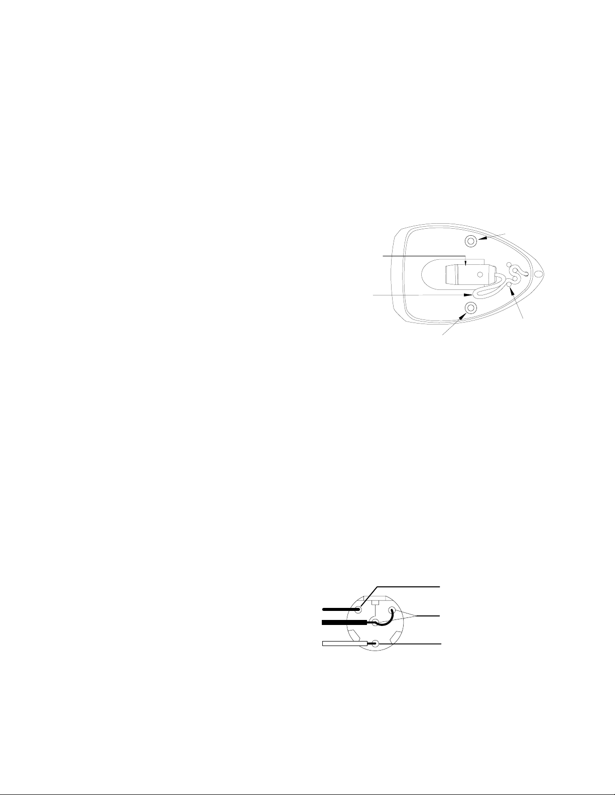
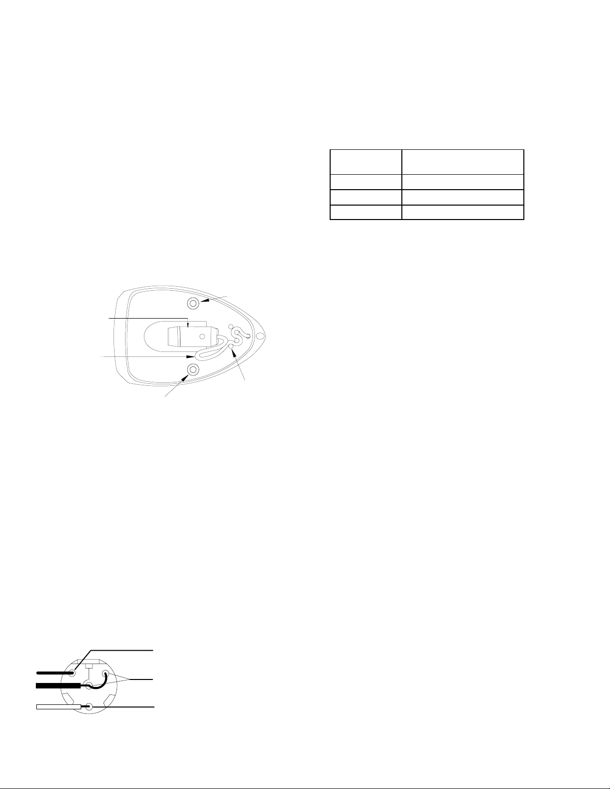
boundary microphone. To re-route the microphone cable through
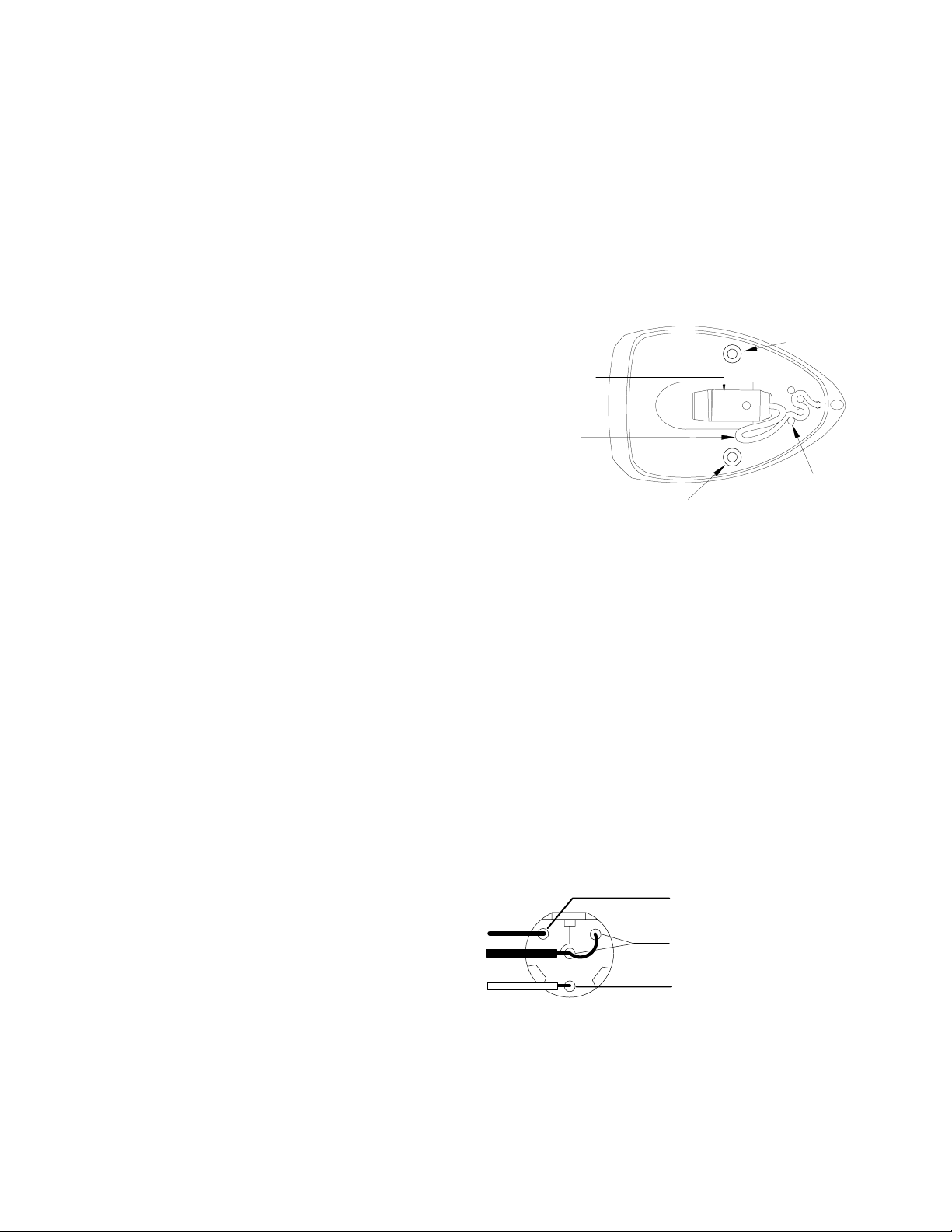
the bottom exit hole, use the following steps (Figure 1):
1. Remove the grille from the microphone base by loosening the
single screw on top of the grille.
2. Remove the 4–pin mini connector from the end of the cable by
cutting the cable just below the connector.
WARNING: Do not attempt to detach the cable from the micro-
phone interface.
3. Secure the cable with your thumb or finger so that it does not
come loose from the strain-relief posts as you thread the cable
out from the rear exit hole.
4. Re-route the cable through the bottom exit hole and pull snug.
IMPORTANT: Be sure the cable is pressed firmly down between the strain relief posts before replacing the grill.
5. Set the grille back into place and thread the screw through the
perforated metal grille and into the microphone interface and
tighten.
6. Use the supplied template (Figure 3) to drill screw holes and a
bottom exit hole in the mounting surface.
7. After threading the cable through the bottom exit hole in the
mounting surface, either re-attach the 4–pin mini connector
(Figure 2) or wire the cable to the screw terminals in the preamplifier (use the supplied rubber strain relief to secure the connection).
NOTE: For detailed instructions on re-attaching the 4–pin mini
connector, contact the Shure Applications Group.
REPAINTING THE MX391 SERIES
Before applying paint to the MX391 series, remove the grille from
the base, remove the foam from the inside of the grill, and mask the
microphone cartridge and interface. Also mask the cable where
necessary.
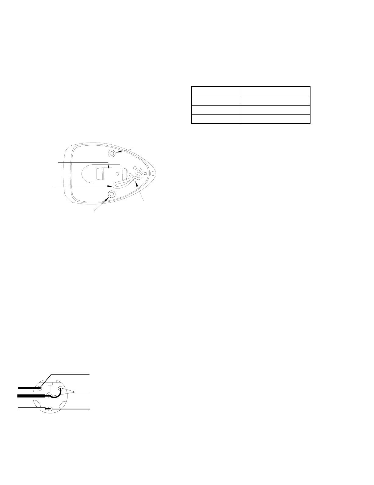
Screw Hole
Microphone Interface
Service Loop
Strain Relief Post
Screw Hole
RE-ROUTING THE CABLE
FIGURE 1
ADJUSTING PREAMP GAIN (Figure 4)
This MX m icrophone i ncludes a n a djustable g ain p reamplifier, allowing the user to specify a 12 d B o r 0 d B g ain s etting. T he pream p s hips
at the 12dB setting. Gain may be decreased by 12dB by moving the
preamp jumpers to the 0dB setting.
2002, Shure Incorporated
27C3027 (BE)
Printed in U.S.A.
Page 2
MICROPHONE SPECIFICATIONS
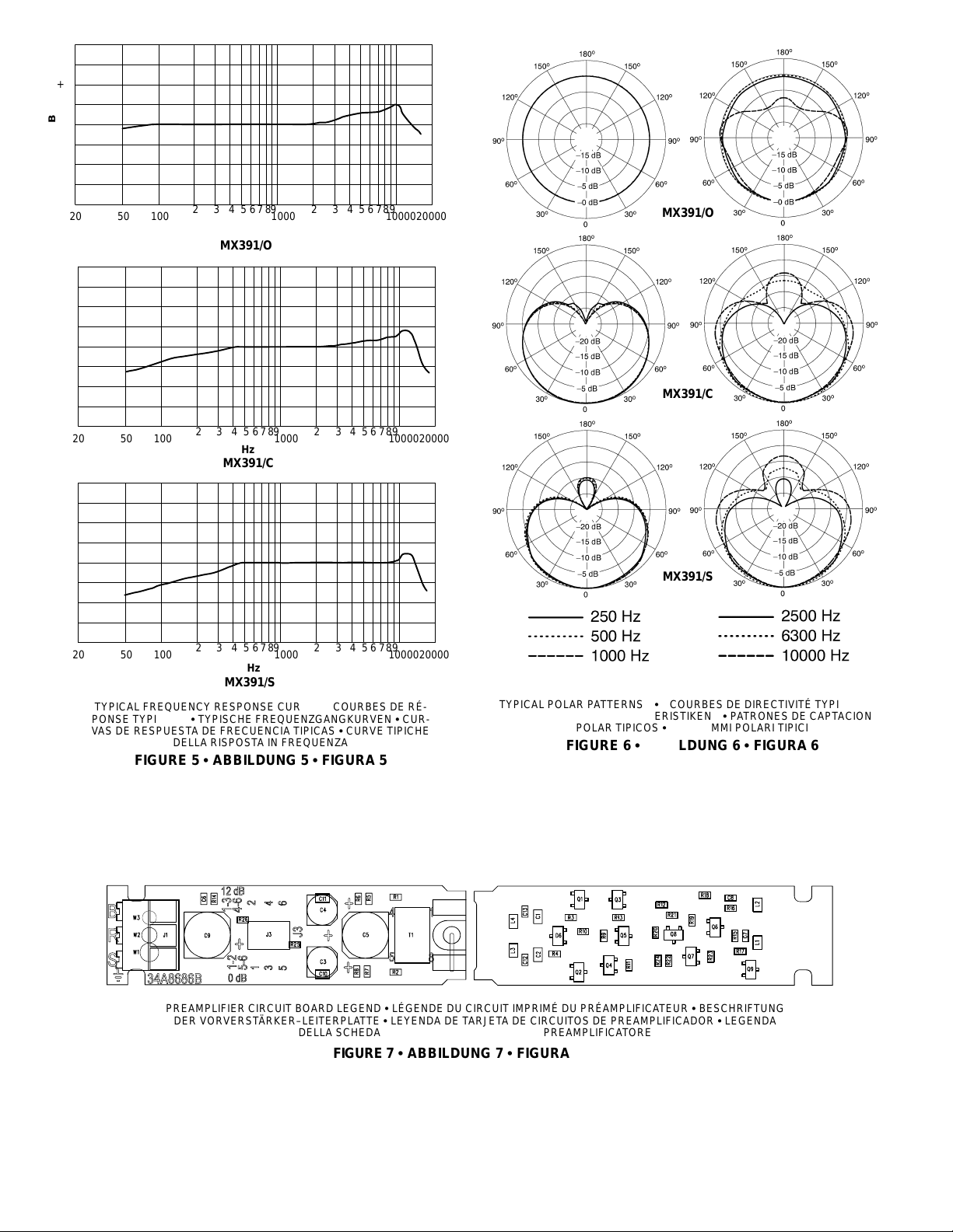
Polar Pattern (Figure 6)
Cardioid (MX391/C, MX391W/C, MX391LP/C, MX391WLP/C)
Supercardioid (MX391/S, MX391W/S, MX391LP/S,
MX391WLP/S)
Omnidirectional (MX391/O, MX391W/O, MX391LP/O,
MX391WLP/O)
Environmental Requirements
Operating Temperature Range: –18° C to 57° C (0° F to 135° F)
Relative Humidity: 0 to 95%
Dimensions
See Figure 3
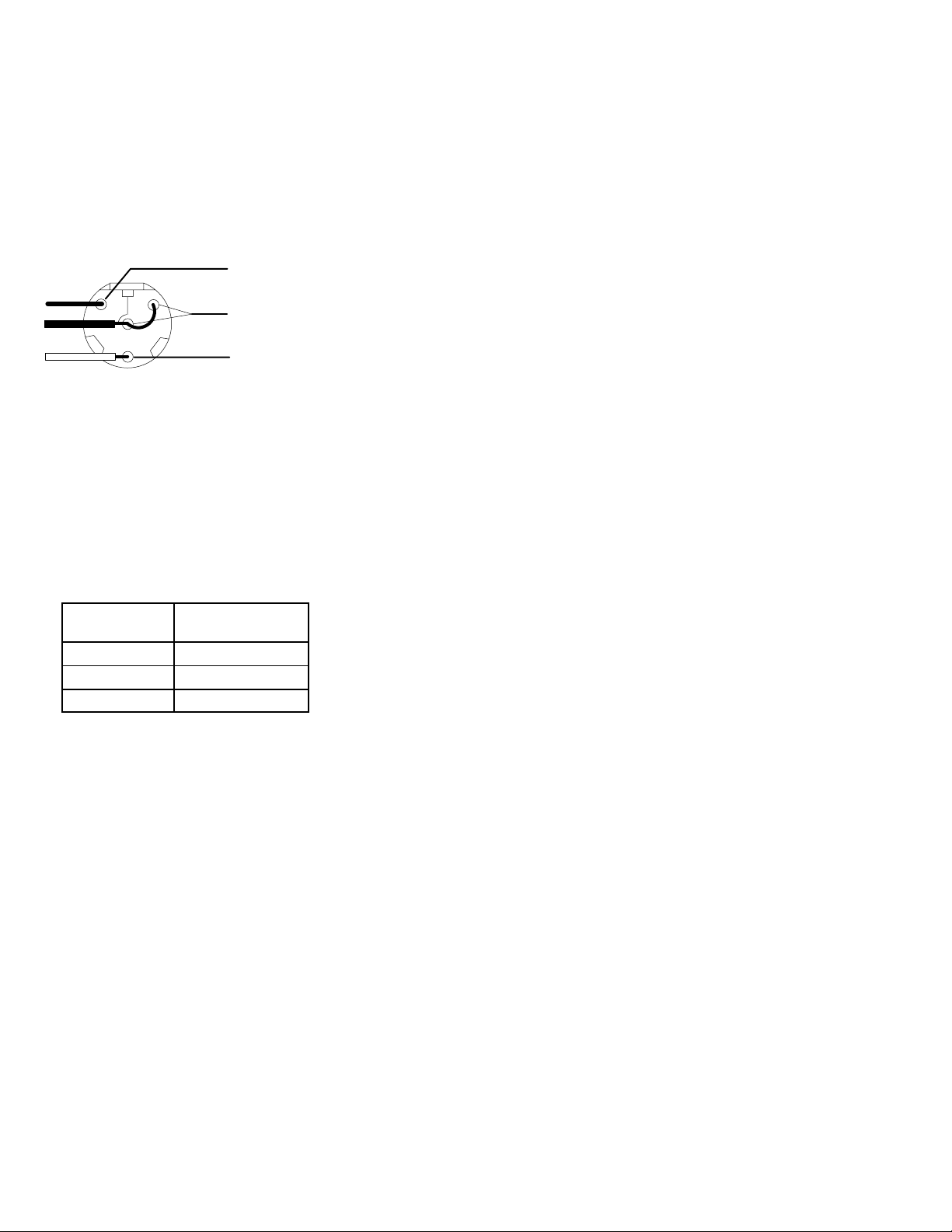
Wiring Diagram
PIN 1 = SHIELD (use only HALF of the
shield, the other half solder to cable
3
1
4
2
PINS 3 and 4 = BLACK LEAD (jumped)
clamp)
PIN 2 = RED LEAD
FIGURE 2
PREAMPLIFIER SPECIFICATIONS
These specifications apply only to the MX391/MX391W microphones when used with the supplied preamplifier. All measurements
taken with the microphone mounted on a 76.2 cm x 76.2 cm (30 in.
x 30 in.) wooden surface and with the sound source incident at 30°
with respect to the surface plane.
Frequency Response (Figure 5)
50 to 17,000 Hz
Output Impedance (at 1000 Hz)
180Ω actual (rated at 150Ω)
Open Circuit Sensitivity
Cartridge Type
Cardioid –29.6 dB (33.5 mV)
Supercardioid –28.3 dB (38.5 mV)
Omnidirectional –21.5 dB (81.4 mV)
All settings –12 dB at 0 gain
*1 Pascal = 94 dB SPL
1 kHz ref. 1 V per
Pascal *
Maximum Sound Pressure Level
(1 kHz at 1% Total Harmonic Distortion, 1 kΩ load)
Cardioid: 118.8 dB
Supercardioid: 117.5 dB
Omnidirectional: 110.7 dB
All settings +6 dB at 0 gain
Signal to Noise Ratio (referenced at 94 dB SPL)
Cardioid: 71.4 dB
Supercardioid: 72.7 dB
Omnidirectional: 79.5 dB
Equivalent Output Noise (A-weighted)
Cardioid: 22.6 dB SPL
Supercardioid: 21.3 dB SPL
Omnidirectional: 14.5 dB SPL
Dynamic Range
at 1 kΩ Load
96.2 dB
100 dB at 0 gain
Common Mode Rejection
45 dB minimum, 10 Hz to 100 kHz
Preamplifier Output Clipping Level
–6 dBV (0.5 V)
–12 dB at 0 gain
Polarity
Positive sound pressure on diaphragm produces positive voltage
on pin 2 relative to pin 3 of the preamplifier XLR output connector.
Power Requirements
11 to 52 Vdc phantom
2.0 mA current consumption
Certification
Eligible to bear CE Marking. Conforms to European EMC
Directive 89/336/EEC. Meets applicable tests and performance
criteria in European Standard EN55103 (1996) parts 1 and 2, for
residential (E1) and light industrial (E2) environments.
REPLACEMENT PARTS
Omnidirectional Cartridge R183B. . . . . . . . . . . . . . . . . . . . . . . . . .
Supercardioid Cartridge R184B. . . . . . . . . . . . . . . . . . . . . . . . . . .
Cardioid Cartridge R185B. . . . . . . . . . . . . . . . . . . . . . . . . . . . . . . .
Preamplifier Kit RK183PK. . . . . . . . . . . . . . . . . . . . . . . . . . . . . . . .
Replacement Cable Kit (black) C123. . . . . . . . . . . . . . . . . . . . . .
Replacement Cable Kit (white) C125. . . . . . . . . . . . . . . . . . . . . .
NOTE: For technical data by Fax, phone 1-800-488-3297 and follow
the recorded instructions. For additional technical assistance, phone
Shure at (847) 866-2200. In Europe, phone 49-7131-72140.
SHURE, the Shure logo, and MICROFLEX are registered trademarks
of Shure Incorporated.
2
Page 3
GÉNÉRALITÉS
Les Shure Microflex série MX391 sont des petits microphones
électrostatiques à électrets à montage en surface conçus pour les
tables de conférence, planchers de scène et lutrins. Grâce à leur
haute sensibilité et vaste gamme de fréquences, ils sont particulièrement indiqués pour le captage de la voix lors de l’amplification
en direct ou des enregistrements.
AVANTAGES
Courbe de réponse plate dans toute la gamme vocale pour un
son non coloré
Cartouches cardioïde, supercardioïde e t om idirectionnelle inter-
changeables perm ettant l ’adaptation optim ale à c haque s ituation
Extra–plat et profilé pour un aspect discret
Sortie équilibrée sans transformateur pour une immunité au
bruit accrue avec de grandes longueurs de câble
Variantes
Les modèles MX391 et MX391W (blanc) sont dotés d’un câble
fixé de 4 mètres (12 pi) avec connecteur miniature 4–broches et d’un
préamplificateur séparé. Le connecteur miniature 4–broches peut
être retiré pour brancher le câble du microphone directement sur les
bornes du préamplificateur. Un soulagement de traction en caoutchouc est fourni pour ce type de montage.
Les modèles MX391LP et MX391WLP (blanc) sont dotés d’un
câble fixé de 4 mètres (12 pi) avec connecteur miniature 4–broches
à quatre broches mais ne sont pas équipés d’un préamplificateur. À
la place, le microphone peut être relié directement à un transmetteur
de poche sans fil Shure.
Les microphones périphériques Microflex
sont fournis avec
l’une de trois cartouches interchangeables, dont le type est indiqué
par le numéro de modèle (sur le dessous de la base du microphone).
Serie MX391/C. Configuration cardioïde pour la sonorisation gé-
nérale. Angle de captage (–3 dB) = 130°.
Serie MX391/S. Configuration supercardioïde pour les applica-
tions exigeant un captage étroit ou à plus grande distance. Angle de
captage (–3 dB) = 115°.
Serie MX391/O. Configuration omnidirectionnelle pour l’enre-
gistrement ou les applications de contrôle à distance. Angle de captage = 360°.
INSTALLATION PERMANENTE
Des trous de vis dans la base du microphone et un trou de sortie
par le bas pour le câble sont prévus pour l’installation permanente
du microphone périphérique. Pour acheminer le câble du microphone par le trou du bas, procéder comme suit (Figure 1):
1. Retirer la grille de la base du microphone en desserrant la vis
unique du dessus.
2. Retirer le connecteur miniature 4–broches en coupant le câble
juste au–dessous du connecteur.
AVERTISSEMENT : Ne pas essayer de détacher le câble de
l’interface du microphone.
3. Maintenir le câble avec le pouce ou le doigt de façon à ce qu’il
ne s’échappe pas des goujons de soulagement de traction
lorsqu’il est sorti du trou arrière.
4. Réacheminer le câble dans le trou de sortie du dessous et le ti-
rer fermement.
IMPORTANT : S’assurer que le câble est bien serré entre les
goujons de soulagement de traction avant de remettre la grille
en place.
5. Remettre la grille en métal perforé en place et insérer la vis dans
cette grille et l’interface du microphone et la serrer.
6. Utiliser le gabarit fourni (Figure 3) pour le perçage des trous de
vis et du trou de sortie par le bas du câble dans la surface de
montage.
7. Une fois le câble passé dans le trou de sortie par le bas de la
surface de montage, soit remonter le connecteur miniature
4–broches (Figure 2), soit brancher le câble sur les bornes à vis
du préamplificateur (utiliser le soulagement de tension en
caoutchouc pour assujettir le branchement).
REMARQUE : Pour des instructions détaillées sur le remon-
tage du connecteur miniature 4–broches, contacter le Groupe
d’applications Shure.
PEINTURE DU SERIE MX391
Avant de peindre le serie MX391, retirer la grille de la base, enlever la mousse de l’intérieur de la grille et masquer la cartouche et l’interface du microphone. Masquer également le câble selon le besoin.
Trou de vis
Interface du
microphone
Boucle de
relaxation
Goujon de
Trou de vis
RÉACHEMINEMENT DU CÂBLE
soulagement de
traction
FIGURE 1
RÉGLAGE DU GAIN DU PRÉAMPLI (Figure 4)
Ce microphone MX comprend un préamplificateur à gain ré-
glable, ce qui permet à l ’utilisateur de choisir un réglage d u g ain
de 12 dB ou de 0 dB. Le préampli est livré avec le réglage à 12
dB. Le gain peut être diminué de 12 dB en déplaçant l es cava-
liers du préampli sur le réglage à 0 dB.
CARACTÉRISTIQUES DU MICROPHONE
Courbe de directivité (Figure 6)
Cardioïde (MX391/C, MX391W/C, MX391LP/C, MX381LPW/C)
Supercardioïde (MX391/S, MX391W/S, MX391LP/S, MX391WLP/S)
Omnidirectionnelle (MX391/O, MX391W/O, MX391LP/O,
MX391WLP/O)
Conditions environnementales
Plage de températures de fonctionnement : –18 à 57 °C
(0 à 135 °F)
Humidité relative : 0 à 95 %
Dimensions
Voir la Figure 3
Schéma de câblage
BROCHE 1 = BLINDAGE (n’utilise que
la moitié du blindage, l’autre moitié se
3
1
4
2
soudant sur la bride du câble)
BROCHES 3 et 4 = FIL NOIR (ponté)
BROCHE 2 = FIL ROUGE
FIGURE 2
3
Page 4

CARACTÉRISTIQUES DU PRÉAMPLIFICATEUR
Ces caractéristiques ne s’appliquent qu’au microphone MX391
lorsqu’il est utilisé avec le préamplificateur fourni. Toutes les mesures ont été prises avec le microphone monté sur une surface en
bois de 76,2 x 76,2 cm (30 x 30 po).
Courbe de réponse (Figure 5)
50 à 17 000 Hz
Impédance de sortie (1000 Hz)
180 Ω réelle (nominal, 150 Ω)
Sensibilité en circuit ouvert
Type de cartouche
Réf. 1 kHz, 1 V par
Pascal *
Cardioïde –29,6 dB (33,5 mV)
Supercardioïde –28,3 dB (38,5 mV)
Omnidirectionnelle –21,5 dB (81,4 mV)
Toutes les configurations –12 dB à 0 gain
*1 Pascal = 94 dB NPA
Pression acoustique maximum
(1 kHz avec 1 % de distorsion harmonique totale et charge de
1 kΩ)
Cardioïde : 118,8 dB
Supercardioïde : 117,5 dB
Omnidirectionnelle : 110,7 dB
+6 dB à 0 gain
Rapport signal/bruit (mesuré avec une pression acoustique de
94 dB NPA)
Cardioïde : 71,4 dB
Supercardioïde : 72,7 dB
Omnidirectionnelle : 79,5 dB
Bruit de sortie équivalent (pondéré en A)
Cardioïde : 22,6 dB NPA
Supercardioïde : 21,3 dB NPA
Omnidirectionnelle : 14,5 dB NPA
Gamme dynamique
vec charge de 1 kW
96,2 dB
100 dB à 0 gain
Rejet en mode commun
45 dB minimum, 10 Hz à 100 kHz
Niveau d’écrêtage de sortie du préamplificateur
–6 dBV (0,5 V)
–12 dB à 0 gain
Polarité
Une pression acoustique positive sur le diaphragme produit une
tension positive sur la broche 2 par rapport à la broche 3 du
connecteur de sortie.
Alimentation
11 à 52 V c.c. duplex
Consommation de courant : 2,0 mA
Homologation
Autorisé à porter la marque CE. Conforme à la directive CEM
européenne 89/336/CEE. Conforme aux critères applicables de
test et de performances de la norme européenne EN 55103
(1996) parties 1 et 2 pour les environnements résidentiels (E1) et
d’industrie légère (E2).
PIÈCES DE RECHANGE
Cartouche omnidirectionnelle R183B. . . . . . . . . . . . . . . . . . . . . .
Cartouche supercardioïde R184B. . . . . . . . . . . . . . . . . . . . . . . . .
Cartouche cardioïde R185B. . . . . . . . . . . . . . . . . . . . . . . . . . . . . .
Kit de préamplificateur RK183PK. . . . . . . . . . . . . . . . . . . . . . . . .
Kit de câble de rechange (noir) C123. . . . . . . . . . . . . . . . . . . . . .
Kit de câble de rechange (blanc) C125. . . . . . . . . . . . . . . . . . . .
REMARQUE : Pour toute information technique par télécopie, compos-
er le 1–800–488–3297 et suivre les instructions de l’enregistrement.
Pour toute assistance technique supplémentaire, appeler Shure au
(847) 866–2200. En Europe, appeler le 49–7131–72140.
ALLGEMEINES
Shure Microflex Mikrofone der Reihe MX391 sind kleine oberflächenmontierte Elektretkondensatormikrofone, die zur Anbringung an Konferenztischen, Bühnenböden und Vortragspulten vorgesehen sind. Durch ihre hohe Empfindlichkeit und den breiten Frequenzbereich eignen sie sich besonders zur Aufnahme von
Sprache und Gesang bei der Tonverstärkung und bei Aufzeichnungsanwendungen.
MERKMALE
Ebener Frequenzgang über den gesamten Stimmbereich für
unverfärbten Klang
Austauschbare Nieren–, Supernieren– und Kugelkapseln, die
optimale Ausrüstung für jede Anwendung ermöglichen
Glattes Flachformdesign für unauffälliges Erscheinungsbild
Symmetrischer transformatorloser Ausgang für gesteigerte
Rauschunempfindlichkeit bei langen Kabelführungen
MODELLVARIANTEN
An den MX391 und MX391W (weiß) –Modellen ist ein 4 Meter
langes Kabel angebracht, das mit einem 4–pin miniatur steckverbindung abgeschlossen ist; sie verfügen außerdem über einen separaten V orverstärker. Auf Wunsch kann der 4–pin miniatur steckverbindung entfernt und das Mikrofonkabel direkt an den Schraubklemmen am Vorverstärker angeschlossen werden. Für dieses Anschlußverfahren wird eine Gummizugentlastung mitgeliefert.
An den MX391LP und MX391WLP (weiß)–Modellen ist ein 4 Meter langes Kabel angebracht, das mit einem 4–pin miniatur steckverbindung abgeschlossen ist; sie verfügen allerdings über keinen V orverstärker. Stattdessen kann das Mikrofon direkt an einen drahtlosen, am Körper getragenen Shure-Sender angeschlossen werden.
Microflex
-Grenzflächenmikrofone werden mit einer der folgenden drei austauschbaren Kapseln geliefert. Die Modellnummer (an
der Unterseite des Mikrofonsockels) gibt an, um welche Ausführung
es sich bei dem Mikrofon handelt.
Der Reihe MX391/C. Nierenrichtcharakteristik für allgemeine
Tonverstärkungsanwendungen. Ansprechwinkel (–3 dB) = 130°.
Der Reihe MX391/S. Supernierenrichtcharakteristik für Ton-
verstärkungsanwendungen, die eine engere oder weiter entfernte
Abdeckung erfordern. Ansprechwinkel (–3 dB) = 115°.
Der Reihe MX391/O. Kugelrichtcharakteristik für Aufzeich-
nungs– oder Fernüberwachungsanwendungen. Ansprechwinkel =
360°.
DAUERHAFTE ANBRINGUNG
Zur dauerhaften Anbringung des Grenzflächenmikrofons sind
Schraubenbohrungen im Mikrofonsockel sowie eine Austrittsöffnung für das Mikrofonkabel an der Unterseite vorgesehen.
Um das Mikrofonkabel durch die Austrittsöffnung an der Unterseite
zu verlegen, sind die folgenden Schritte auszuführen (Abbildung 1):
1. Den Grill vom Mikrofonsockel abnehmen, indem die Schraube
an der Oberseite des Grills gelöst wird.
2. Den 4–pin miniatur steckverbindung vom Kabelende entfernen,
indem das Kabel unmittelbar vor dem Steckverbinder durchgeschnitten wird.
ACHTUNG: Nicht versuchen, das Kabel von der Mikrofonschnittstelle abzunehmen.
3. Das Kabel mit dem Daumen oder einem Finger festhalten, so
daß es sich nicht von den Zugentlastungsstiften löst, während
das Kabel durch die Austrittsöffnung an der Rückseite nach au-
ßen geführt wird.
4. Das Kabel durch die Austrittsöffnung an der Unterseite verle-
gen und straffziehen:
4
Page 5
WICHTIG: Sicherstellen, daß das Kabel fest zwischen die Zu-
gentlastungsstifte gedrückt wird, bevor der Grill wieder angebracht wird.
5. Den Grill wieder anbringen und die Schraube durch den Metallgrill und in die Mikrofonschnittstelle einschrauben und festziehen.
6. Mit der mitgelieferten Schablone (Abbildung 3) Schraubenbohrungen und eine Austrittsöffnung an der Unterseite in die Befestigungsfläche bohren.
7. Nachdem das Kabel durch die Austrittsöffnung an der Untersei-
te der Befestigungsfläche geführt wurde, entweder den 4–pin
miniatur steckverbindung (Abbildung 2) wieder anbringen oder
das Kabel mit den Schraubklemmen am Vorverstärker verdrahten (dabei die Gummizugentlastung verwenden, um die Verbindung zu sichern).
HINWEIS: Detaillierte Anweisungen für die Anbringung des
4–pin miniatur steckverbindung sind von der Shure Applications Group (Anwendungsabteilung) zu erhalten.
NEULACKIERUNG DER REIHE MX391
Vor dem Lackieren der reihe MX391 den Grill vom Sockel abnehmen, den Schaumstoff aus dem Innern des Grills entfernen und Mikrofonkapsel und –schnittstelle abdecken. Nötigenfalls auch das Ka-
bel abdecken.
Schraubenbohrung
ikrofonschnittstelle
Wartungsschleife
Schraubenbohrung
NEUVERLEGUNG DES KABELS
Zugentlastungsstift
ABBILDUNG 1
EINSTELLUNG DER VORVERSTÄRKER–VERSTÄR-
KUNG (Abbildung 4)
Dieses MX–Mikrofon enthält einen Vorverstärker mit Verstärkungseinstellung, der dem Benutzer ermöglicht, eine 12–dB–
oder 0–dB–Verstärkungseinstellung zu wählen. Der Vorverstärker wird mit der 12–dB–Einstellung versandt. Die Verstärkung kann um 12 dB verringert werden, indem die Vorverstärker–Jumper auf die 0–dB–Einstellung verlegt werden.
TECHNISCHE DATEN DES MIKROFONS
Richtcharakteristik (Abbildung 6)
Niere (MX391/C, MX391W/C, MX391LP/C, MX381LPW/C)
Superniere (MX391/S, MX391W/S, MX391LP/S, MX391WLP/S)
Kugel (MX391/O, MX391W/O, MX391LP/O, MX391WLP/O)
Betriebsbedingungen
Betriebstemperaturbereich: –18 °C bis 57 °C
Relative Feuchtigkeit: 0 bis 95 %
Abmessungen
Siehe Abbildung 3
Schaltplan
STIFT 1 = ABSCHIRMUNG (nur die
HÄLFTE der Abschirmung verwenden, die
3
1
4
2
andere Hälfte an die Kabelklemme löten)
STIFT 3 und 4 = SCHWARZE LEITUNG
(mit Überbrückungskabel)
STIFT 2 = ROTE LEITUNG
ABBILDUNG 2
TECHNISCHE DATEN DES VORVERSTÄRKERS
Diese technischen Daten gelten für das Mikrofon M X391 nur
dann, wenn e s g emeinsam m it d em m itgelieferten Vorverstärker
verwendet wird. Alle Messungen erfolgten nach Befestigung
des Mikrofons an einer Holzoberfläche mit den Maßen 76,2 c m
x 76,2 cm.
Frequenzgang (Abbildung 5)
50 bis 17.000 Hz
Ausgangsimpedanz (1000 Hz)
Ist-Wert: 180 Ω (Zulassung: 150 Ω)
Leerlaufempfindlichkeit
Kapseltyp
1 kHz bezogen auf 1 V je
Pascal *
Niere –29,6 dB (33,5 mV)
Superniere –28,3 dB (38,5 mV)
Kugel –21,5 dB (81,4 mV)
Alle Einstellungen –12 dB bei Gewinn 0
*1 Mikrobar = 74 dB Schalldruckpegel **1 Pascal = 94 dB Schalldruckpegel
Maximaler Schalldruckpegel
(1 kHz bei 1% Gesamtklirrfaktor, 1 kΩ Last)
Niere: 118,8 dB
Superniere: 117,5 dB
Kugel: 110,7 dB
Alle Einstellungen +6 dB bei Gewinn 0
Signal-Rauschabstand (bezogen auf 94 dB Schalldruckpegel)
Niere: 71,4 dB
Superniere: 72,7 dB
Kugel: 79,5 dB
Äquivalentausgangsrauschen (mit A-Gewichtung)
Niere: 22,6 dB
Schalldruckpegel
Superniere: 21,3 dB Schalldruckpegel
Kugel: 14,5 dB Schalldruckpegel
Dynamikbereich bei 1 kW Belastung
96,2 dB
100 dB bei Gewinn 0
Gleichtaktunterdrückung
mindestens 45 dB, 10 Hz bis 100 kHz
Vorverstärkerausgang-Begrenzungspegel
–6 dBV (0,5 V)
–12 dB bei Gewinn 0
Polarität
Positiver Schalldruck an der Membran erzeugt positive Spannung an Stift 2 in Bezug auf Stift 3 des Ausgangssteckverbinders.
Leistungsbedarf
11 bis 52 V Phantom-Gleichspannung
2,0 mA Stromverbrauch
Zertifizierung
Zur CE–Kennzeichnung berechtigt. Entspricht der EU–Richtlinie
über elektromagnetische Verträglichkeit 89/336/EEC. Erfüllt die
Prüfungs– und Leistungskriterien der europäischen Norm EN
55103 (1996) T eil 1 und 2 für Wohngebiete (E1) und Leichtindus-
triegebiete (E2).
ERSATZTEILE
Kugelkapsel R183B. . . . . . . . . . . . . . . . . . . . . . . . . . . . . . . . . . . . .
Supernierenkapsel R184B. . . . . . . . . . . . . . . . . . . . . . . . . . . . . . .
Nierenkapsel R185B. . . . . . . . . . . . . . . . . . . . . . . . . . . . . . . . . . . .
Vorverstärkersatz RK183PK. . . . . . . . . . . . . . . . . . . . . . . . . . . . . .
Ersatzkabelsatz (schwartze) C123. . . . . . . . . . . . . . . . . . . . . . . .
Ersatzkabelsatz (weiss) C125. . . . . . . . . . . . . . . . . . . . . . . . . . . .
HINWEIS: Faxabruf technischer Daten unter der Rufnummer
1–800–488–3297 (nur innerhalb der USA), dabei Anleitungen des Anrufbeantworters befolgen. Weitere technische Unterstützung wird von
Shure unter der Rufnummer 1 (847) 866–2200 geleistet. In Europa bitte
49 (7131) 72140 anrufen.
5
Page 6
GENERALIDADES
Los micrófonos Microflex serie MX391 de Shure son micrófonos
de condensador de electreto pequeños que se montan en superficies planas, diseñados para montarse en mesas de conferencias,
pisos de escenarios y atriles. Su alta sensibilidad y amplia gama de
frecuencias los hacen particularmente útiles para la captación de
oradores o cantantes para situaciones de refuerzo o de grabación
de sonido.
CARACTERISTICAS
Respuesta de frecuencia uniforme por la gama de frecuencias
de voz para no alterar el tono del sonido
Cápsulas intercambiables con patrones de captación de car-
dioide, supercardioide y omnidireccional que permiten usar la
alternativa óptima para cada situación
Su diseño e stilizado y d e b ajo p erfil t iene u na a pariencia d iscreta
Salidas equilibradas sin uso de transformadores para aumen-
tar la inmunidad a los ruidos en tramos largos de cable
VARIEDADES DE MODELOS
Los modelos MX391 y MX391W (blanco) tienen un cable de 4 m
(12 pies) con un conector miniatura de 4 clavijas y un preamplificador independiente. Alternativamente, se puede quitar el conector
miniatura de 4 clavijas y conectar el cable directamente a los bornes
de tornillo del preamplificador. Se proporciona un amortiguador de
esfuerzos de caucho para este tipo de conexión.
Los modelos MX391LP y MX391WLP (blanco) vienen con un
cable de 4 m (12 pies) con un conector miniatura de 4 clavijas, pero
no incluyen el preamplificador. En su lugar, el micrófono puede con-
ectarse directamente a un emisor portátil inalámbrico Shure.
Los micrófonos de frontera Microflex
vienen con una de tres
cápsulas intercambiables, identificadas por el número de modelo
(hallado en la parte inferior de la base del micrófono).
SERIE MX391/C. Patrón de captación de cardioide para aplica-
ciones de refuerzo de sonido en general. Angulo de captación (nivel
de –3 dB) = 130°.
SERIE MX391/S. Patrón de captación de supercardioide para
aplicaciones de refuerzo de sonido en las cuales la zona de cobertura es más estrecha o se requiere un alcance mayor. Angulo de captación (nivel de –3 dB) = 115°.
SERIE MX391/O. Patrón de captación omnidireccional para apli-
caciones de grabación y de monitoreo remoto de sonido. Angulo de
captación = 360°.
INSTALACION PERMANENTE
La base del micrófono tiene agujeros para tornillo y un agujero de
salida para el cable que permiten instalar el micrófono de frontera
de modo permanente. Para pasar el cable de micrófono a través del
agujero inferior de salida, ejecute los pasos siguientes (Vea la
Figura 1):
1. Quite la rejilla de la base del micrófono aflojando el tornillo que
está en la parte superior de la rejilla.
2. Quite el conector miniatura de 4 clavijas cortando el extremo
del cable justo debajo del conector.
ADVERTENCIA: No intente desconectar el cable de la interfaz
del micrófono.
3. Sostenga el cable con uno de sus dedos para que no se salga
de las espigas amortiguadoras de esfuerzos al sacar el cable
por el agujero de salida trasero.
4. Pase el cable a través del agujero inferior de salida y estírelo.
IMPORTANTE: Asegúrese que el cable quede firmemente op-
rimido entre las espigas amortiguadoras de esfuerzos antes de
volver a colocar la rejilla.
5. Vuelva a colocar la rejilla en su lugar y atornille el tornillo a tra-
vés de la rejilla metálica perforada y de la interfaz del micrófono
y apriételo.
6. Utilice la plantilla provista (Figura 3) para taladrar los agujeros
para tornillo y un agujero de salida inferior en la superficie de
montaje.
7. Después de pasar el cable a través del agujero de salida inferior
de la superficie de montaje, vuelva a conectar el conector miniatura de 4 clavijas (Figura 2), o bien conecte el cable a los bornes de tornillo del preamplificador (utilice el amortiguador de
esfuerzos de caucho provisto para fijar la conexión).
NOTA: Para más detalles en cuanto a la conexión del conector
miniatura de 4 clavijas, comuníquese con Shure Applications
Group.
PARA VOLVER A PINTAR EL SERIE MX391
Antes de volver a pintar el serie MX391, quite la rejilla de la base,
saque el elemento de espuma del interior de la rejilla y proteja la
cápsula y la interfaz del micrófono. También proteja el cable donde
sea necesario.
Agujero para
tornillo
Interfaz del
micrófono
Lazo adicional
Espiga amortiguadora
Agujero para tornillo
REDISPOSICION DEL CABLE
de esfuerzos
FIGURA 1
AJUSTE DE LA GANANCIA DEL PREAMPLIFICADOR
Este micrófono MX incluye un preamplificador con ganancia
ajustable que permite al u suario e specificar una g anancia de 1 2
ó 0 dB. El preamplificador se despacha ajus tado para 12 dB.
La ganancia puede reducirse en 12 dB si se mueven los
puentes del preamplificador a la posición de 0 dB.
ESPECIFICACIONES DEL MICROFONO
Patrón polar (Figura 6)
Cardioide (MX391/C, MX391W/C, MX391LP/C. MX391WLP/C)
Supercardioide (MX391/S, MX391W/S, MX391LP/S. M X391WLP/S)
Omnidireccional (MX391/O MX391W/S, MX391LP/S.
MX391WLP/S)
Requisitos de entorno
Gama de temperatura de funcionamiento: –18° a 57°C (0° a
135°F)
Humedad relativa: 0 a 95%
Dimensiones
Vea la Figura 3
Diagrama de alambrado
CLAVIJA 1 = BLINDAJE (utilice sólo
LA MITAD del blindaje, suelde la otra
3
1
4
2
mitad a la abrazadera del cable)
CLAVIJAS 3 y 4 = CONDUCTOR
NEGRO (con puente)
CLAVIJA 2 = CONDUCTOR ROJO
FIGURA 2
6
Page 7

ESPECIFICACIONES DEL PREAMPLIFICADOR
Estas especificaciones corresponden únicamente a un micrófono
MX391 utilizado juntamente con el preamplificador suministrado.
Todas las mediciones se han hecho con el micrófono montado en
una superficie de madera de 76,2 x 76,2 cm (30 x 30 pulg).
Respuesta de frecuencia (Figura 5)
50 a 17.000 Hz
Impedancia de salida (1000 Hz)
180 Ω reales (150 Ω nominales)
Sensibilidad en circuito abierto
Tipo de cápsula
1 kHz ref., respecto a 1 V por
Pascal *
Cardioide –29,6 dB (33,5 mV)
Supercardioide –28,3 dB (38,5 mV)
Omnidireccional –21,5 dB (81,4 mV)
Todos los ajuste son de –12 dB con ganancia en 0
*1 Pascal = 94 dB SPL
Nivel de presión acústica máximo (1 kHz con 1% de distorsión
armónica total y carga de 1 kΩ)
Cardioide: 118,8 dB
Supercardioide: 117,5 dB
Omnidireccional: 110,7 dB
Todos los ajuste son de +6 dB con ganancia en 0
Relación de señal a ruido (con presión acústica de referencia
de 94 dB)
Cardioide: 71,4 dB
Supercardioide: 72,7 dB
Omnidireccional: 79,5 dB
Ruido equivalente de salida (ponderación A)
Cardioide: 22,6 dB
Supercardioide: 21,3 dB
Omnidireccional: 14,5 dB
Gama dinámica
con carga de 1 kW
96,2 dB
100 dB con ganancia en 0
Rechazo en modo común
45 dB mínimo, 10 Hz a 100 kHz
Nivel de limitación de salida del preamplificador
–6 dBV (0,5 V)
–12 dB con ganancia en 0
Polaridad
Una presión positiva en el diafragma del micrófono produce un
voltaje positivo en la clavija 2 con respecto a la clavija 3 del
conector de salida.
Requisitos de alimentación
11 a 52 VCC alimentación fantasma
Consume 2,0 mA de corriente
Certificaciones
Califica para llevar las marcas CE. Cumple la directiva europea
89/336/EEC de compatibilidad electromagnética. Se ajusta a los
criterios correspondientes de verificación y funcionamiento
establecidos en la norma europea EN 55103 (1996), partes 1 y
2, para zonas residenciales (E1) y zonas de industria ligera (E2).
REPUESTOS
Cápsula omnidireccional R183B. . . . . . . . . . . . . . . . . . . . . . . . . .
Cápsula de supercardioide R184B. . . . . . . . . . . . . . . . . . . . . . . .
Cápsula de cardioide R185B. . . . . . . . . . . . . . . . . . . . . . . . . . . . .
Juego de preamplificador RK183PK. . . . . . . . . . . . . . . . . . . . . . .
Juego de cable de repuesto (negro) C123. . . . . . . . . . . . . . . . . .
Juego de cable de repuesto (blanco) C125. . . . . . . . . . . . . . . . .
NOTA: Para obtener información técnica vía Fax, llame al
1–800–488–3297 y siga las instrucciones dadas en la grabación. Para
recibir soporte técnico adicional, llame a Shure al teléfono (847)
866–2200. En Europa, llame al 49–7131–72140.
DESCRIZIONE GENERALE
I modelli Shure serie Microflex MX391 sono microfoni compatti,
a condensatore con elettrete a montaggio superficiale, realizzati per
tavoli da conferenza, palcoscenici e leggii. L’alta sensibilità e l’eleva-
ta gamma di frequenze li rende particolarmente adatti alla ricezione
di segnali musicali ed oratori in impianti di amplificazione sonora e
di registrazione.
CARATTERISTICHE
Risposta in frequenza costante in tutta la gamma vocale, per ot-
tenere un suono “non colorato”
Capsule a cardioide, supercardioide e omnidirezionali inter-
cambiabili, ai fini della scelta ottimale per ogni applicazione
Profilo compatto, elegante, non appariscente
Uscita bilanciata, senza trasformatore, per ottenere una mag-
giore immunità dal rumore in lunghi tratti di cavo
DESCRIZIONE DEI MODELLI
I modelli MX391 e MX391W (bianco) sono dotati di un cavo (collegato) di 4 metri (12 piedi) dotato di connettore in miniatura a 4–piedini e di un preamplificatore separato. Se lo si desidera, si può rimuovere il connettore in miniatura a 4–piedini e collegare il cavo diretta-
mente ai terminali ad avvitamento del preamplificatore. Per questo
tipo di questo collegamento è fornito un pressacavo di gomma.
I modelli MX391LP e MX391WLP (bianco) sono dotati di un cavo
(collegato) di 4 metri (12 piedi) terminato con un connettore in miniatura a 4–piedini, ma non includono preamplificatore. Invece, il microfono può essere collegato direttamente a un trasmettitore Body-
Pack senza fili Shure.
I microfoni Microflex
a effetto di contorno sono forniti con uno dei
tre tipi di capsule intercambiabili, indicato dal numero di modello (riportato sul fondo della base del microfono).
SERIE MX391/C. Diagramma di ricezione a cardiode per impianti
di amplificazione sonora generali. Angolo di ricezione (–3 dB) =
130°.
SERIE MX391/S. Diagramma di ricezione a supercardiode per
impianti di amplificazione sonora che richiedono direttività o portata
maggiore. Angolo di ricezione (–3 dB) = 115°.
SERIE MX391/O. Diagramma di ricezione omnidirezionale per
applicazioni di registrazione o monitoraggio a distanza. Angolo di ricezione = 360°.
INSTALLAZIONE PERMANENTE
Ai fini di un’installazione permanente dei microfoni a ef fetto di contorno, nella base del microfono ci sono fori per viti e un foro di uscita
inferiore per il cavo microfonico. Per cambiare la posizione del cavo
in modo da farlo uscire dal foro inferiore, procedere come segue(Vedi Figura 1).
1. Rimuovere la griglia dalla base del microfono allentando la vite
inserita nella sua parte superiore.
2. Rimuovere il connettore in miniatura a 4–piedini dall’estremità
del cavo tagliando quest’ultimo appena sotto il connettore stesso.
AVVERTENZA – Non tentare di staccare il cavo dall’interfaccia
del microfono.
3. Man mano che si fa uscire il cavo dal foro posteriore, usare le
dita per mantenerlo tra gli appositi cilindretti antisollecitazione.
4. Fare uscire il cavo dal foro inferiore e tirarlo per eliminare tutto
il lasco.
IMPORTANTE – Prima di riposizionare la griglia, accertarsi che
il cavo sia premuto saldamente verso il basso tra i cilindretti antisollecitazione.
7
Page 8
5. Riposizionare la griglia metallica perforata, inserire la vite nella
griglia e nell’interfaccia del microfono, quindi serrarla.
6. Servirsi della dima in dotazione (Figura 3) per praticare con un
trapano nella superficie di montaggio i fori per le viti e quello di
uscita inferiore.
7. Dopo aver infilato il cavo nella superficie di montaggio attraver-
so il foro di uscita inferiore, ricollegare il connettore in miniatura
a 4–piedini (Figura 2) o collegare il cavo ai terminali ad avvita-
mento del preamplificatore (per eseguire la connessione, utilizzare il pressacavo di gomma in dotazione).
DATI TECNICI DEL PREAMPLIFICATORE
Questi dati tecnici valgono solo per il microfono MX391, se viene
usato con il preamplificatore in dotazione. Tutte le misure sono state
eseguite con il microfono montato su una superficie di legno di 76,2
x 76,2 cm (30 x 30 pollici)
Risposta in frequenza (Figura 5)
Da 50 a 17000 Hz
Impedenza di uscita (1000 Hz)
180 Ω effettivi (valore nominale di 150 Ω)
Sensibilità a circuito aperto
NOTA – Per istruzioni dettagliate sul ricollegamento del con-
nettore in miniatura a 4–piedini, rivolgersi allo Shure Applications Group.
RIVERNICIATURA DEL SERIE MX391
Prima di verniciare l’MX391, rimuovere la griglia dalla base e la
schiuma dall’interno della griglia, e proteggere con del nastro la capsula e l’interfaccia del microfono. Se necessario, nastrare anche il
cavo.
Foro per vite
Interfaccia
microfono
Tratto di cavo
per interventi
Cilindretto
Foro per vite
CAMBIO DELLA POSIZIONE DEL CAVO
antisollecitazione
FIGURA 1
REGOLAZIONE DEL GUADAGNO DEL PREAMPLIFICATORE (Figura 4)
Questo microfono MX è dotato di un preamplificatore a guadagno regolabile su 12 dB o 0 dB. In fabbric a il guadagno del
preamplificatore è stato regolato a 12 dB; può essere ridotto
di 12 dB spostandone i ponticelli sulla p osizione corrispondente
a 0 dB.
DATI TECNICI DEL MICROFONO
Diagramma polare (Figura 6)
Cardioide (MX391/C, MX391W/C, MX391LP/C, MX391WLP/C)
Supercardioide (MX391/S, MX391W/S, MX391LP/S, M X391WLP/S)
Omnidirezionale (MX391/O, MX391W/O, MX391LP/O,
MX391WLP/O)
Requisiti ambientali
Campo della temperatura di esercizio: da –18 a 57 °C (da 0 a
135 °F)
Umidità relativa: da 0 a 95%
Dimensioni
Vedi Figura 3
Schema di collegamento
PIEDINO 1 = SCHERMATURA (usare solo
METÀ della schermatura, l’altra metà va
3
1
4
2
brasata al fermacavo)
PIEDINI 3 e 4 = CONDUTTORE NERO
(collegati con un ponticello)
PIEDINO 2 = CONDUTTORE ROSSO
FIGURA 2
Tipo di capsula
1 kHz, rif. 1 V a pascal *
Cardioide –29,6 dB (33,5 mV)
Supercardioide –28,3 dB (38,5 mV)
Omnidirezionale –21,5 dB (81,4 mV)
Tutte le impostazioni –12 dB a guadagno 0
*1 pascal = 94 dB di SPL
Livello di pressione sonora (SPL) max.
(1 kHz a 1% di distorsione armonica totale, carico di 1 kΩ)
Cardioide: 118,8 dB
Supercardioide: 117,5 dB
Omnidirezionale: 110,7 dB
Tutte le impostazioni +6 dB a guadagno 0
Rapporto segnale/rumore (con 94 dB di SPL)
Cardioide: 71,4 dB
Supercardioide: 72,7 dB
Omnidirezionale: 79,5 dB
Rumore equivalente di uscita (ponderato A)
Cardioide: 22,6 dB
di pressione sonora
Supercardioide: 21,3 dB di pressione sonora
Omnidirezionale: 14,5 dB di pressione sonora
Gamma dinamica con carico di 1 kW
96,2 dB
100 dB a guadagno 0
Reiezione di modo comune
45 dB min., da 10 Hz a 100 kHz
Livello di limitazione all’uscita del preamplificatore
–6 dBV (0,5 V)
–12 dB a guadagno 0
Polarità
Una pressione sonora positiva sul diaframma produce una
tensione positiva sul piedino 2 rispetto al piedino 3 del connettore
di uscita.
Requisiti di alimentazione
Da 11 a 52 V c.c., virtuale
2,0 mA di assorbimento di corrente
CERTIFICAZIONI
Contrassegnabile con il marchio CE. Conforme alla direttiva
europea sulla compatibilità elettromagnetica 89/336/CEE. Conforme ai criteri sulle prestazioni e alle prove pertinenti specificati
nella norma europea EN 55103 (1996) parti 1 e 2, per ambienti
residenziali (E1) e industriali leggeri (E2).
COMPONENTI DI RICAMBIO
Capsula omnidirezionale R183B. . . . . . . . . . . . . . . . . . . . . . . . . .
Capsula a supercardioide R184B. . . . . . . . . . . . . . . . . . . . . . . . .
Capsula a cardioide R185B. . . . . . . . . . . . . . . . . . . . . . . . . . . . . .
Kit preamplificatore RK183PK. . . . . . . . . . . . . . . . . . . . . . . . . . . .
Kit del cavo di ricambio (nero) C123. . . . . . . . . . . . . . . . . . . . . . .
Kit del cavo di ricambio (bianco) C125. . . . . . . . . . . . . . . . . . . . .
NOTA: Per ricevere dati tecnici via fax, chiamare il numero
1–800–488–3297 (solo negli USA) e seguire le istruzioni registrate. Per
ulteriore assistenza tecnica, chiamare la Shure al numero USA (847)
866–2200. In Europa, chiamare il numero 49–7131–72140.
8
Page 9
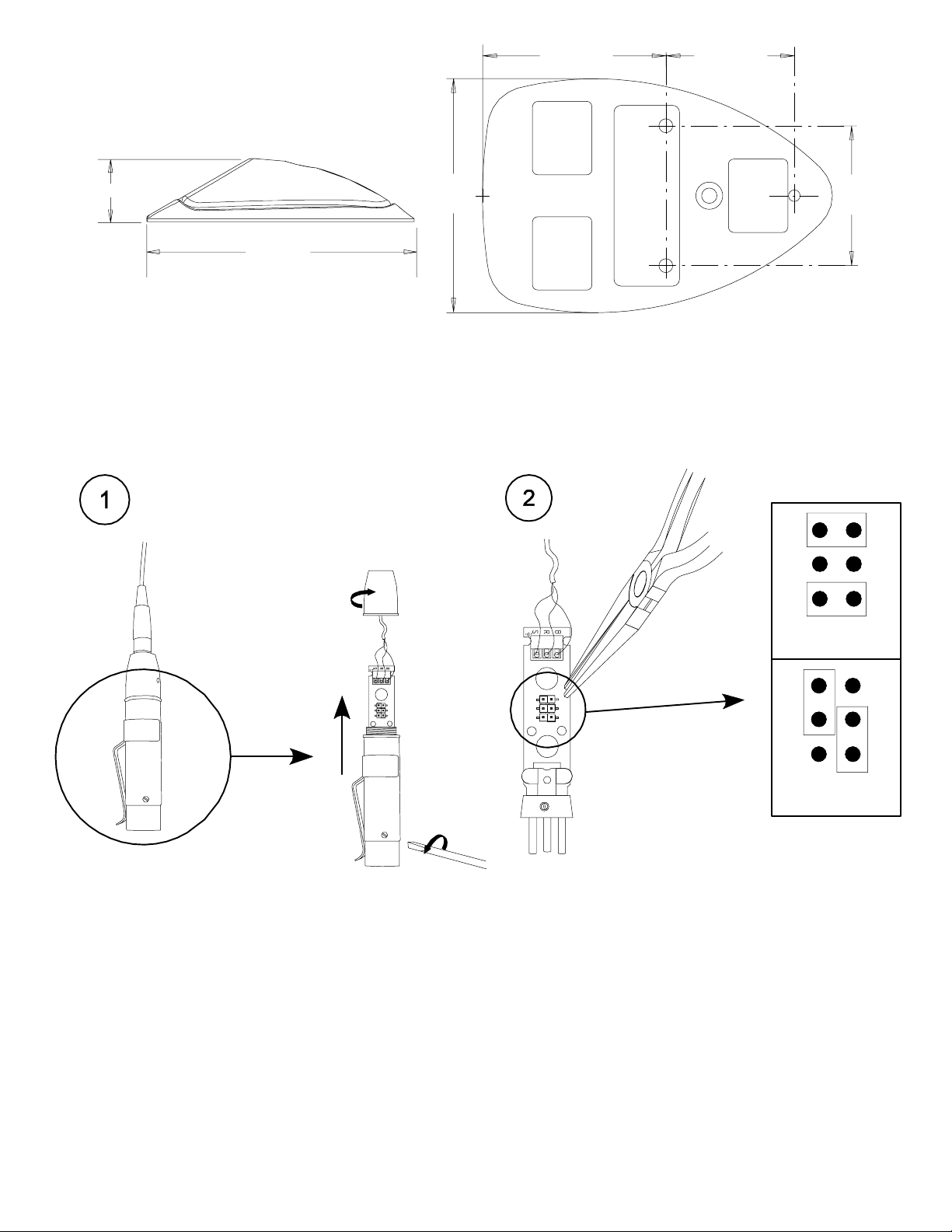
4.158 cm
(1.637 in.)
2.921 cm
(1.150 in.)
1.905 cm (.750 in.)
7.940 cm
(3.126 in.)
SIDE (3/4 SCALE) CÔTÉ (ÉCHELLE 3/4) SEITENANSICHT (MASSSTAB 3:4)
COSTADO (ESCALA: 3/4 DE TAMAÑO REAL) VISTA LATERALE (SCALA 3/4)
DIMENSIONS ABMESSUNGEN DIMENSIONES DIMENSIONI
FIGURE 3 ABBILDUNG 3 FIGURA 3
5.304 cm
(2.088 in.)
3.175 cm
(1.250 in.)
BOTTOM (ACTUAL SIZE) DESSOUS
(GRANDEUR NATURE) UNTERSEITE
(ORIGINALGRÖSSE) LADO INFERIOR
(TAMAÑO REAL) VISTA DAL BASSO (AL VERO)
1
2
3
4
5
6
PREAMP GAIN ADJUSTMENT (412S and 418S ONLY) RÉGLAGE DE DE PRÉAMPLI
VORVERSTÄRKERVERSTÄRKUNGSEINSTELLUNG AJUSTE DE GANANCIA DEL
PREAMPLIFICACIÓN REGISTRAZIONE DI GUADAGNO DELLA PREAMPLIFICAZIONE
FIGURE 4 S ABBILDUNG 4 S FIGURA 4
0 dB
1
2
3
12 dB
4
5
6
9
Page 10
+1
dB
–1
0
0
0
100
5020
432
Hz
MX391/O
+1
0
dB
0
–1
0
100
5020
432
Hz
MX391/C
+1
0
dB
0
–1
0
100
5020
432
Hz
MX391/S
TYPICAL FREQUENCY RESPONSE CURVES COURBES DE RÉ-
PONSE TYPIQUES TYPISCHE FREQUENZGANGKURVEN CUR-
VAS DE RESPUESTA DE FRECUENCIA TIPICAS CURVE TIPICHE
DELLA RISPOSTA IN FREQUENZA
FIGURE 5 ABBILDUNG 5 FIGURA 5
9876543298765
20000100001000
MX391/O
MX391/C
9876543298765
20000100001000
MX391/S
9876543298765
20000100001000
TYPICAL POLAR PATTERNS COURBES DE DIRECTIVITÉ TYPIQUES
TYPISCHE RICHTCHARAKTERISTIKEN PATRONES DE CAPTACION
POLAR TIPICOS DIAGRAMMI POLARI TIPICI
FIGURE 6 ABBILDUNG 6 FIGURA 6
PREAMPLIFIER CIRCUIT BOARD LEGEND LÉGENDE DU CIRCUIT IMPRIMÉ DU PRÉAMPLIFICATEUR BESCHRIFTUNG
DER VORVERSTÄRKER–LEITERPLATTE LEYENDA DE TARJET A DE CIRCUITOS DE PREAMPLIFICADOR LEGENDA
DELLA SCHEDA DI CIRCUITI DEI MODELLI DEL PREAMPLIFICATORE
FIGURE 7 ABBILDUNG 7 FIGURA 7
10
Page 11
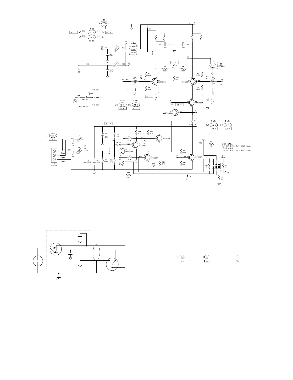
R27
R1
100
100
R28
R2
100
100
PREAMPLIFIER SCHEMATIC DIAGRAM SCHÉMA DE PRINCIPE DU PRÉAMPLIFICATEUR STROMLAUFPLAN
FÜR VORVERSTÄRKER DIAGRAMA ESQUEMATICO DEL PREAMPLIFICADOR SCHEMA CIRCUITALE DEI
MODELLI DEL PREAMPLIFICATORE
FIGURE 8 ABBILDUNG 8 FIGURA 8
FET
MIC
ELEMENT
MICROPHONE WIRING DIAGRAM SCHÉMA DE CÂBLAGE DU MICROPHONE
MIKROFONSCHALTPLAN DIAGRAMA DE ALAMBRADO DEL MICROFONO
86E8958
220 pF
220 pF
1
4
2
WHITE/SHIELD BLANC/BLINDAJE
WEIß/SCHILD BLANCO/BLINDAJE
RED ROUGE ROT ROJO ROSSO
BLACK NOIR SCHWARZ
BIANCO/SCHERMATURA
NEGRO NERO
SCHEMA CIRCUITALE DEL MICROFONO
3
NOTES:
1. All resistors1/10 Watt, 1%, 0805 unless otherwise specified.
2. Electrolytic capacitors shown in µF, ±10%, 50V or more, unlss
otherwise specified.
3. The following symbols denote:
A.C. Voltage
D.C. Voltage
(+) / (–) indicate A.C. polarity
relative to input test signal.
A.C. Voltage, Mic Off
D.C. Voltage, Mic Off
Printed Clrcuit Ground
Case Ground
4. All voltages measured with input driven by a 0.1 Vrms, 1kHz signal
through the test circuit shown below . A Shure M367 mixer or equivalent, with 48 V phantom power switched on, supplies the required
power and load to preamplifier.
11
Page 12

12
SHURE Incorporated Web Address: http://www.shure.com
222 Hartrey Avenue, Evanston, IL 60202–3696, U.S.A.
Phone: 847-866–2200 Fax: 847-866-2279
In Europe, Phone: 49-7131-72140 Fax: 49-7131-721414
In Asia, Phone: 852-2893-4290 Fax: 852-2893-4055
Elsewhere, Phone: 847-866–2200 Fax: 847-866-2585
 Loading...