

Shure Microflex MX300 Series User Manual
GENERAL
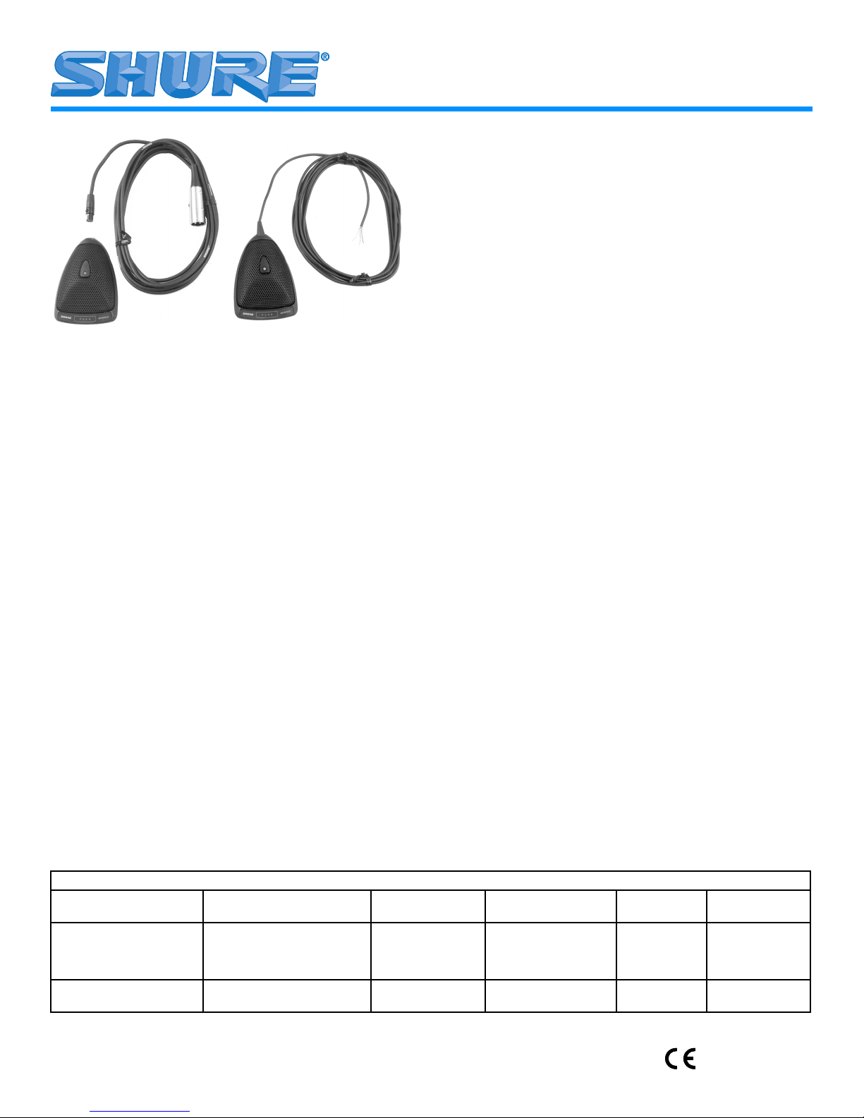
Shure Microflex MX300 Series microphones are surface-mounted electret condenser microphones designed primarily
for mounting on conference tables, stage floors, and lecterns.
Their high sensitivity and wide frequency range make them especially suitable for picking up speech and vocals in sound reinforcement and recording applications. Interchangeable cartridges
provide the installer with greater flexibility and make it possible to
easily reconfigure microphone coverage as the need arises. The
MX392 and MX393 models include an internal preamplifier.
MX300 Series microphones take advantage of the principle that,
at a barrier or boundary, the sound pressure level doubles. When
placed near a sufficiently large boundary surface, the microphone
has 6 dB higher sensitivity and approximately 3 dB greater direct-to-reverberant sound ratio.
FEATURES
• Flat frequency response across the vocal range for
uncolored sound
• Interchangeable cardioid, supercardioid, and
omnidirectional cartridges that provide choices for
applications
• Sleek, low-profile design for unobtrusive appearance
• Balanced transformerless output for increased immunity
to noise over long cable runs
• Low susceptibility to electromagnetic hum and RFI
• Programmable on/off switch and LED on/off indicator
• Logic input/output terminals for remote control or use with
automatic mixers (MX392 models only)
Microflex MX300 Series User Guide
Boundary Microphones
MODEL VARIATIONS
•
MX392 Models
grammable membrane on/off switch, logic input/output terminals, an on/off indicator LED, screw terminal connections, and
attached unterminated cable.
•
MX393 Models
grammable membrane on/off switch, an on/off indicator LED,
and a miniature, three pin connector.
SELECTING A CARTRIDGE
All Microflex microphones are available with any one of three interchangeable cartridges. The polar pattern of the original cartridge used in a particular microphone is indicated by the model
number suffix:
Cardioid (C). Recommended for general sound reinforcement
applications. Pickup angle (-3 dB) = 130°.
Supercardioid (S). Recommended for sound reinforcement applications requiring narrow or more distant coverage. Pickup angle
(-3 dB) = 115°.
Omnidirectional (O). Recommended for recording or remote
monitoring applications. Pickup angle (-3 dB) = 360°.
MICROPHONE PLACEMENT
To maintain the flattest possible low-frequency response and
optimum rejection of background noise, place the microphone on
a flat surface that is as large as possible. The surface can be a
floor, table, or lectern.
NOTE: Avoid locating microphones near reflective
surfaces other than the boundary surface (i.e., beveled
sides of pulpits or overhanging shelves). Failure to do
so will result in increased levels of reverberant sound.
: Surface-mount microphone; includes a pro-
: Surface-mount microphone; includes a pro-
MICROPHONE APPLICATION AND SELECTION GUIDE
Application Mounting Surface Microphone to
Sound reinforcement for
speech and vocals
Recording or remote moni-
toring of speech and vocals
©2004, Shure Incorporated
27E2834 (Rev. 5)
Lectern, pulpit, stage floor, or
conference table
Lectern, pulpit, stage floor, or
conference table
Cable Connector
Hard Wired
Hard Wired
TA3F
TA3F
Hard Wired
TA3F
Cable Output
Connector
Hard Wired
Hard Wired
XLR
XLR
Hard Wired
XLR
Polar Pattern Microflex Model
Cardioid
Supercardioid
Cardioid
Supercardioid
Omnidirectional
Omnidirectional
MX392/C
MX392/S
MX393/C
MX393/S
MX392/O
MX393/O
Printed in U.S.A.

SECURING MICROPHONES TO A MOUNTING
SURFACE (Figure 1 on page 21)
1. Remove the Phillips screw from the bottom of the microphone base, then remove the retainer.
2. Remove the grille and foam screen by carefully inserting a pointed tool into the edge of the grille and prying it
open.
3. Place the microphone in the desired location and, using
a pencil, trace the location of the screw holes through
the microphone. Then drill a starter hole for each supplied screw.
4. Cover the rear two foam pads on the microphone with
tape so that it slides more easily across the mounting
surface.
5. Install the two supplied screws in the desired location on
the mounting surface.
6. Reinstall the grille, foam screen, and retainer, and secure them with the Phillips screw.
7. Using a knife or a razor blade, cut a slot into each of the
two foam pads covering the slots below the screw holes
on the bottom of the microphone.
8. Position the microphone so that the screw holes fit over
the screw heads. Then slide the microphone so that the
screw heads are in the slots in the microphone base.
IMPORTANT: For proper shielding, maintain
electrical continuity between the grille and the
metal base.
13. Reinstall the retainer, grille, foam screen, and Phillips
screw.
CHANGING THE MICROPHONE CARTRIDGE (Figure 3
on page 21)
1. Remove the Phillips screw from the bottom of the microphone base, then remove the retainer.
2. Remove the grille and foam screen by carefully inserting a pointed tool into the edge of the grille and prying it
open.
3. Remove the Phillips screw from the cartridge retaining
bracket, then remove the bracket.
4. Use your fingers to unscrew the cartridge from the microphone assembly.
5. Use your fingers to screw the replacement cartridge into
place.
6. Reinstall the cartridge retaining bracket and secure it
with the Phillips screw.
7. Reinstall the grille, foam screen, and retainer, then secure them with the Phillips screw.
PAINTING THE MICROPHONE (Figure 2 on page 21)
1. Remove the Phillips screw from the bottom of the microphone base, then remove the retainer.
2. Lift off the retainer, grille, and foam screen. Then separate the foam screen from the grille.If using an MX393
model, disconnect the TA4F miniature 4-pin connector.
If you are using an MX392 model, disconnect the wire
leads from the screw terminals, untie the knot in the cable, and slide the cable out.
3. Remove the rubber strain relief.
4. Place the supplied plastic paint shield over the exposed
circuit board.
5. Place the supplied adhesive masking strip over the
switch panel on the front of the base.
6. Cover the connector opening on the microphone base
with the supplied round rubber plug.
7. Cleanse the surfaces to be painted with denatured alcohol or naphtha.
8. Carefully spray paint the microphone base and grille the
desired color. To avoid filling grille holes, apply paint in
a thin layer. Allow paint to dry thoroughly before reinstalling the grille and foam screen.
9. If using an MX392 model, thread the cable through the
base, then through the rubber strain relief.
10. If using an MX392 model, tie a single overhand knot in
the cable as near to the end of the cable jacket as possible. Then insert the rubber strain relief back into the
cable exit hole.
11. Reconnect the wire leads to the screw terminals.
12. Use fine sandpaper to remove any paint that may have
adhered to the bottom edges of the grille.
RE-ROUTING CABLE FOR BOTTOM EXIT
(Figure 4, on page 21 MX392 models only)
1. Remove the Phillips screw from the bottom of the microphone base, then remove the retainer.
2. Carefully lift off the grille and foam screen, using a pointed tool or screwdriver.
3. Disconnect the wire leads from the screw terminals on
the microphone printed circuit board.
4. Untie the knot in the cable, and slide the cable out.
5. Remove the rubber strain relief from the inside of the
microphone.
6. Insert the cable through the slot between the two screw
holes, starting from the bottom of the microphone base.
7. Tie a single overhand knot in the cable from inside the
microphone. This will help prevent the cable from being
accidentally pulled out.
8. Connect the wire leads to the screw terminals on the microphone circuit board.
9. Insert the supplied round rubber plug in the unused cable exit hole.
10. Reinstall the grille, foam screen, and retainer, and secure them with the Phillips screw.
11. Secure the microphone to the mounting surface. Refer
to the “Securing Microphones to a Mounting Surface”
paragraph.
INTERNAL DIP SWITCH FUNCTIONS
All MX392 and MX393 models have internal DIP switches that
allow the user to change the behavior of the microphone On/Off
switch. To gain access to the logic terminals, remove the grille re-
(Figure 5 on page 21)
2
tainer screw, the grille retainer, foam screen, and grille, as shown
in Figure 2 on page 21.
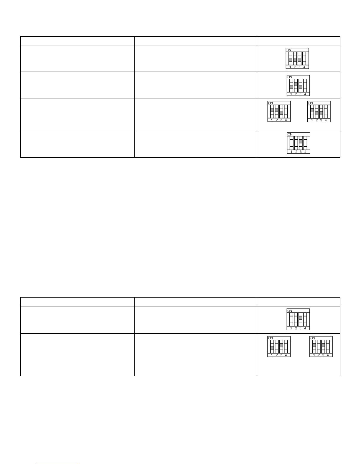
SWITCH BEHAVIOR LED BEHAVIOR DIP SWITCH SETTINGS
Push to Mute, Release to Talk (As Shipped) LED on when microphone is active
Push to Talk, Release to Mute LED on when microphone is active
Toggle: Push On/Push Off LED on when microphone is active
Initially Muted Initially Active
Microphone Always Active (switch available
LED Always OFF
for logic functions only)
NOTE: S4 is available for custom applications. When S4 is in
the ON position, pad W4 is connected to pad W5 (see Figure 10 on
page 23).
MX392 LOGIC TERMINAL DEFINITIONS
(Figure 6 on page 22)
LOGIC GND Terminal: Connects to the logic ground of an au-
tomatic mixer, switcher, or other equipment. Can be modified to
prevent ground loops.
SWITCH OUT Terminal: Provides a TTL logic low when the
membrane switch is pressed. This signal is available at all times for
all switch settings. The Switch Out function provides a momentary
closure when S1 is Off and a latching closure when S1 is On.
LED IN Terminal: Can be modified to remotely control the LED
by flipping DIP switch S3 in the microphone to the ON position. As
supplied, the LED IN terminal draws 5 Vdc. When this is shorted to
the LOGIC GROUND terminal, the LED turns on.
SWITCH BEHAVIOR USER ACTION REQUIRED DIP SWITCH SETTINGS
Switch Deactivated,
Microphone Always Active
Short LED IN terminal to LOGIC GROUND terminal
LED Always ON
MX392 LOGIC MODIFICATIONS
Open the microphone as shown in Figure 2 on page 21.
Isolating Logic Ground from Audio Ground
1. Remove jumper R40 from the top of the circuit board.
2. Make sure LOGIC GND terminal connects to the logic
ground of the automatic mixer, switcher, or other equipment.
Changing SWITCH OUT Terminal to Always Momentary
To accommodate interface equipment requiring momentary closure of the microphone (even when the desired microphone function is latching on/off), proceed as follows:
1. Remove R45 from the top of the circuit board.
2. Reinstall R45 at location R46 on the top of the circuit
board
Automatic Mixer Mode (MX392 models only) Connect SWITCH OUT signal to various logic in-
puts of automatic mixer for custom functions
Connect mixer channel GATE OUT to microphone
LED IN. LED on microphone turns on when its
channel is gated on
3
Switch out is logic
low while switch is
pressed
Switch toggles
switch out to
logic low

SPECIFICATIONS
All measurements taken with microphone mounted on a wood-
en surface 76.2 cm x 76.2 cm (30 in. x 30 in.).
Frequency Response (Figure 7 on page 22)
50 to 17,000 Hz
Polar Pattern (Figure 8 on page 22)
Cardioid (MX392/C, MX393/C)
Supercardioid (MX392/S, MX393/S)
Omnidirectional (MX392/O, MX393/O)
Output Impedance
EIA Rated at 150 Ω (180 Ω actual)
Sensitivity (at 1 kHz, open circuit voltage)
Cardioid Cartridge: -27.5 dBV/Pa (42.2 mV)
Supercardioid Cartridge: -26.5 dBV/Pa (47.3 mV)
Omnidirectional: -22.0 dBV/Pa (79.4 mV)
1 Pascal=94 dB SPL
Maximum Sound Pressure Level
(1 kHz at 1% Total Harmonic Distortion, 1 kΩ load)
Cardioid: 117.0 dB
Supercardioid: 116.0 dB
Omnidirectional: 111.5 dB
Signal to Noise Ratio (referenced at 94 dB SPL)
Cardioid: 71.0 dB
Supercardioid: 72.0 dB
Omnidirectional: 76.5 dB
Equivalent Output Noise (A-weighted)
Cardioid: 23.0 dB
Supercardioid: 22.0 dB
Omnidirectional: 17.5 dB
Dynamic Range
94.0 dB
Common Mode Rejection
45 dB minimum, 10 Hz to 100 kHz
Switch Attenuation
50 dB minimum
Preamplifier Output Clipping Level
-6 dBV (0.5 V)
Polarity
Positive sound pressure on diaphragm produces positive volt-
age on pin 2 relative to pin 3 of output connector.
Logic Connections (MX392 Only)
LED IN: Active low (≤1.0v), TTL compatible. Absolute maxi-
mum voltage: -0.7V to 50V.
SWITCH OUT: Active low (≤0.5V), sinks up to 20mA, TTL com-
patible. Absolute maximum voltage: -0.7V to 24V (up to 50V
through 3kΩ).
Power Requirements
11 to 52 Vdc phantom
2.0 mA current consumption
Environmental Requirements
Operating Temperature Range: -18° C to 57° C (0° F to 135° F)
Relative Humidity: 0 to 95%
Dimensions (Figure 9 on page 23)
Certification
Eligible to bear CE Marking. Conforms to European EMC Direc-
tive 89/336/EEC. Meets applicable tests and performance cri-
teria in European Standard EN55103 (1996) parts 1 and 2, for
residential (E1) and light industrial (E2) environments.
FURNISHED ACCESSORIES
Zipper Bag ............................................................26A14
Paint Mask ..........................................................80C514
Switch Paint Mask...............................................80A541
Paint Plug............................................................36A664
12' (3.7m) Cable 3-Pin Miniature Connector (TA3F)
to male XLR (MX393) ............................................. C119
REPLACEMENT PARTS
Omnidirectional Cartridge .......................................R183
Supercardioid Cartridge..........................................R184
Cardioid Cartridge...................................................R185
SHURE, the Shure logo, and MICROFLEX are
registered trademarks of Shure Incorporated.
Guide de l'utilisateur des microphones périphériques Microflex série MX300
GÉNÉRALITÉS
Les Shure Microflex série MX300 sont des microphones électrostatiques à électret, à montage en surface, conçus principalement pour les tables de conférence, planchers de scène et lutrins.
Grâce à leur haute sensibilité et vaste gamme de fréquences, ils
sont particulièrement indiqués pour le captage de la voix lors de
l'amplification en direct ou des enregistrements. Les cartouches interchangeables assurent une plus grande souplesse d'utilisation et
permettent de reconfigurer aisément la portée du microphone en
fonction des besoins. Les modèles MX392 et MX393 sont dotés
d'un préamplificateur interne.
Les microphones série MX300 tirent parti du fait que lorsque le
son rencontre un obstacle, le niveau de pression acoustique double. Placé près d'une surface obstacle assez grande, le microphone présente une sensibilité accrue de 6 dB et un rapport son direct
à réverbérant accru de 3 dB.
AVANTAGES :
• Courbe de réponse plate dans toute la gamme vocale
pour un son non coloré
• Cartouches cardioïdes, supercardioïdes et
omidirectionnelles interchangeables permettant
l'adaptation optimale à chaque situation
• Discret grâce à sa conception profilée et surbaissée
• Sortie sans transformateur pour une immunité au bruit
accrue avec de grandes longueurs de fil
• Basse susceptibilité aux ronflements électromagnétiques
et radiofréquences
• Interrupteur marche/arrêt programmable et
témoin DEL
• Bornes d'entrée/sortie logique pour télécommande ou
usage avec mélangeurs automatiques (modèles MX392
seulement)
4
VARIANTES
Modèles MX392 : Microphone à montage en surface avec inter-
rupteur programmable à membrane marche/arrêt, bornes d'entrée/sortie logique, témoin marche/arrêt, connecteur à vis et câble
fixe sans connecteur.
Modèles MX393 : Microphone à montage en surface avec interrupteur programmable à membrane marche/arrêt, témoin marche/arrêt et connecteur mini TA4F.
CHOIX DE LA CARTOUCHE
Tous les microphones Microflex sont offerts avec l'une des trois
cartouches interchangeables. La courbe de directivité de la cartouche d'origine de chaque microphone est indiquée par le suffixe du
numéro de modèle :
Cardioïde (C). Recommandée pour les applications de sonorisation générale. Angle de captage (-3 dB) = 130°.
GUIDE DE SÉLECTION ET D'APPLICATION DES MICROPHONES
Application Surface de montage Connecteur micro-
Sonorisation de la voix Lutrin, chaire, plancher de
Enregistrement ou
contrôle à distance de
la voix
scène ou table de conférence
Lutrin, chaire, plancher de
scène ou table de conférence
phone à câble
Câblé
Câblé
TA3F
TA3F
Câblé
TA3F
Supercardioïde (S). Recommandée pour les applications de
sonorisation exigeant un captage plus étroit ou à plus grande distance. Angle de captage (-3 dB) = 115°.
Omnidirectionnelle (O). Recomandée pour l'enregistrement
ou le captage à distance. Angle de captage (-3 dB) = 360°
PLACEMENT DU MICROPHONE
Pour obtenir une courbe de réponse la plus plate possible et
une réjection maximum des bruits de fond, placer le microphone
sur une surface plane, la plus grande possible. Cette surface peut
être un plancher, une table ou un lutrin.
REMARQUE : Éviter de placer les microphones près de
surfaces réverbérantes autres que les surfaces limites
(par ex., bords en biais des lutrins ou étagères
suspendues). Ce placement causerait un niveau accru
du son réverbérant.
Connecteur de sortie
de câble
Câblé
Câblé
XLR
XLR
Câblé
XLR
Courbe de directivité Modèle
Microflex
Cardioïde
Supercardioïde
Cardioïde
Supercardioïde
Omnidirectionnelle
Omnidirectionnelle
MX392/C
MX392/S
MX393/C
MX393/S
MX392/O
MX393/O
FIXATION DES MICROPHONES SUR UNE SURFACE DE
MONTAGE (Figure 1, page 21)
1. Retirer la vis Phillips du bas de la base du microphone
et enlever la retenue.
2. Retirer la grille et l'écran de mousse en insérant avec
précaution la pointe d'un outil acéré dans le bord de la
grille et en faisant levier.
3. Placer le microphone à l'endroit désiré et, à l'aide d'un
crayon, marquer l'emplacement des vis en utilisant le
microphone comme gabarit. Percer un trou de guidage
pour chacune des vis fournies.
4. Couvrir les deux coussinets de mousse arrière du microphone de ruban adhésif de façon à ce qu'il puisse
glisser plus facilement sur la surface de montage.
5. Installer les deux vis fournies à l'endroit désiré de la surface de montage.Remettre la grille, l'écran de mousse
et la retenue en place et les assujettir avec la vis
Phillips.
6. À l'aide d'un couteau ou d'une lame de rasoir, découper
une fente dans chacun des coussinets de mousse couvrant les fentes situées au-dessous des trous de vis du
dessous du microphone.
7. Positionner le microphone de façon à ce que les trous
de vis se trouvent au-dessus des têtes des vis. Glisser
ensuite le microphone de façon à engager les têtes des
vis dans les fentes de la base du microphone.
PEINTURE DU MICROPHONE (Figure 2, page 21)
1. Retirer la vis Phillips du bas de la base du microphone
et enlever la retenue.
2. Retirer la grille et l'écran de mousse. Séparer l'écran de
mousse de la grille.
3. Dans le cas d'un modèle MX393, débrancher le connecteur mini TA4F. Sur les modèles MX392, débrancher
les fils des bornes à vis, défaire le noeud du câble et retirer le câble.
4. Retirer le soulagement de traction en caoutchouc.
5. Placer la protection pour peinture en plastique fournie
sur le circuit exposé.
6. Placer le ruban adhésif de masquage fourni sur le panneau d'interrupteur du devant de la base.
7. Obturer l'ouverture de connecteur de la base du microphone à l'aide du bouchon rond en caoutchouc fourni.
8. Nettoyer les surfaces à peindre avec de l'alcool dénaturé ou du naphte.
9. Vaporiser la base et la grille du microphone de peinture
de la couleur désirée. Pour éviter de colmater les trous
de la grille, appliquer la peinture en couches minces.
Laisser sécher complètement avant de remettre la grille
et l'écran de mousse en place.
10. Sur le modèle MX392, enfiler le câble dans la base puis
dans le soulagement de contrainte en caoutchouc.
11. Sur le modèle MX392, faire un noeud simple sur le câble, aussi près que possible de l'extrémité de la gaine.
Remettre le soulagement de contrainte en caoutchouc
en place, dans le trou de sortie du câble.
12. Rebrancher les fils sur les bornes à vis.
5

13. Éliminer la peinture ayant éventuellement adhéré sur
les bords inférieurs de la grille à l'aide d'un papier abrasif fin.
IMPORTANT : Pour un blindage correct, maintenir la
continuité électrique entre la grille et la base métallique.
14. Remettre la retenue, la grille, l'écran de mousse et la vis
Phillips en place.
REMPLACEMENT DE LA CARTOUCHE DU
MICROPHONE (Figure 3, page 21)
1. Retirer la vis Phillips du bas de la base du microphone
et enlever la retenue.
2. Retirer la grille et l'écran de mousse en insérant avec
précaution la point d'un outil acéré dans le bord de la
grille et en faisant levier.
3. Retirer la vis Phillips du support de la cartouche et enlever le support.
4. Avec les doigts, dévisser la cartouche du corps du microphone.
5. Procéder de même pour mettre la nouvelle cartouche
en place.
6. Remonter le support de la cartouche et l'assujettir avec
la vis Phillips.
7. Remettre la grille, l'écran de mousse et la retenue en
place et les assujettir avec la vis Phillips.
FONCTIONS DU COMMUTATEUR À POSITIONS
MULTIPLES INTERNE (Figure 5, page 21)
Tous les modèles MX392 et MX393 sont dotés d'un commutateur à positions multiples permettant à l'utilisateur de programmer
l'interrupteur marche/arrêt en fonction des applications. Pour accéder à ce commutateur à positions multiples, retirer la vis de retenue
de la grille, la retenue, l'écran de mousse et la grille, comme illustré
à la Figure 2, page 21.
DÉFINITION DES BORNES DE LOGIQUE DU MX392
(Figure 6, page 22)
Borne MASSE LOGIQUE : pour la connexion à la masse logique d'une table de mélange automatique, d'un commutateur ou
d'un autre appareil. Peut être modifiée pour empêcher les boucles
de masse. Voir le paragraphe “Modifications de logique du
MX392”.
Borne de COUPURE : procure un niveau de logique TTL bas
lorsque l'interrupteur à membrane est actionné. Ce signal est
constamment disponible avec tous les réglages d'interrupteur. La
fonction de coupure permet de couper le microphone momentanément lorsque l'interrupteur DIP 1 est sur arrêt ou en permanence
lorsque l'interrupteur est sur marche.
MODIFICATIONS DE LOGIQUE DU MX392
Pour accéder aux bornes de logique, retirer la vis de retenue de
la grille, la retenue, l'écran de mousse et la grille, comme illustré à
la Figure 2, page 21.
RÉACHEMINEMENT DU CÂBLE POUR LA SORTIE PAR
LE BAS (Figure 4, page 21, MODÈLES MX392
UNIQUEMENT)
1. Retirer la vis Phillips du dessous de la base du microphone et enlever la retenue.
2. Avec précaution, soulever la grille et l'écran de mousse
à l'aide d'un outil acéré ou d'un tournevis fin et les retirer.
3. Débrancher les fils des bornes à vis du circuit imprimé
du microphone.
4. Défaire le noeud du câble et retirer le câble.
5. Retirer le soulagement de traction en caoutchouc de
l'intérieur du microphone.
6. Insérer le câble dans les fentes se trouvant entre les
deux trous de vis, en partant du dessous de la base du
microphone.
7. Faire un noeud simple sur la partie du câble se trouvant
à l'intérieur du microphone. Ceci empêchera que le câble soit accidentellement débranché.
8. Rebrancher les fils sur les bornes à vis du circuit imprimé.
9. Placer le bouchon rond en caoutchouc fourni dans le
trou de sortie de câble inutilisé.
10. Remettre la grille, l'écran de mousse et la retenue en
place et les assujettir avec la vis Phillips.
11. Assujettir le microphone sur la surface de montage. Voir
le paragraphe “Fixation du microphone sur la surface de
montage”.
Isolation de la masse logique de la masse audio
1. Retirer le cavalier R40 du dessus du circuit imprimé.
2. S'assurer que la borne de MASSE LOGIQUE est connectée à la masse logique de la table de mélange automatique, du commutateur ou d'un autre appareil.
Configuration de la borne de COUPURE pour la
coupure momentanée permanente
Pour l'utilisation avec un dispositif d'interface exigeant la coupure momentanée du microphone (même si la fonction de microphone désirée est verrouillable), procéder comme suit :
1. Retirer le cavalier R45 du dessus du circuit imprimé.
2. L'installer sur la position R46 du dessus du circuit
imprimé.
6
Modifications spéciales
L'interrupteur S4 permet les modifications spéciales. Lorsqu'il
est en position de MARCHE, W4 est connecté à W5.
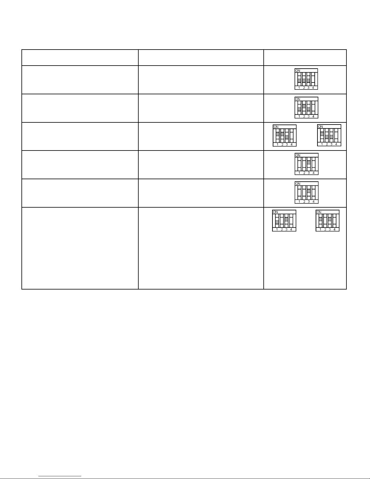
FONCTION DE MICROPHONE DÉSIRÉE ACTION REQUISE RÉGLAGES DES
INTERRUPTEURS
Appuyer pour couper (réglage usine) Maintenir l'interrupteur enfoncé pour couper le
microphone; le relâcher pour rouvrir le micro.
Le témoin s'allume lorsque le microphone est
ouvert.
Appuyer pour parler Maintenir l'interrupteur enfoncé pour ouvrir le
microphone; le relâcher pour couper le micro.
Le témoin s'allume lorsque le microphone est
ouvert.
Appuyer pour ouvrir/couper Appuyer sur l'interrupteur pour alternativement
ouvrir et couper le microphone.
Le témoin s'allume lorsque le microphone est
ouvert.
Interrupteur désactivé, microphone ouvert
en permanence
Témoin toujours ÉTEINT
Interrupteur désactivé, microphone ouvert
en permanence
Mode de table de mélange automatique
(modèles MX392 seulement)
REMARQUE : L'interrupteur S4 permet les
modifications
spéciales.
Relier la borne d'ENTRÉE de DEL à la MASSE
LOGIQUE
Témoin toujours allumé
Si S1 = ARRÊT, le signal de COUPURE sera
momentanément en niveau logique bas lorsque
l'interrupteur est actionné.
Si S1 = MARCHE, le signal de COUPURE
verrouillera le niveau logique bas lorsque
l'interrupteur est actionné.
Brancher le signal de COUPURE sur les diverses
entrées logiques d'une table de mélange
automatique pour obtenir les fonctions spéciales.
Raccorder la SORTIE PORTE de voie de la table
de mélange à l'entrée DEL du microphone. La DEL
s'allume lorsque cette voie est activée.
CARACTÉRISTIQUES
Toutes les mesures ont été prises avec le microphone monté
sur une surface en bois de 76,2 cm x 76,2 cm.
Courbe de réponse (Figure 7, page 22)
50 à 17 000 Hz
Courbe de directivité (Figure 8, page 22)
Cardioïde (MX392/C, MX393/C)
Supercardioïde (MX392/S, MX393/S)
Omnidirectionnelle (MX392/O, MX393/O)
Impédance de sortie
Nominale EIA, 150 Ω (180 Ω réelle)
Sensibilité (à 1 kHz, tension en circuit ouvert)
Cartouche cardioïde : -27,5 dBV/Pa (42,2 mV)
Cartouche Supercardioïde : -26,5 dBV/Pa (47,3 mV)
Omnidirectionnelle : -22,0 dBV/Pa (79,4 mV)
1 Pascal=94 dB SPL
Pression acoustique maximum
(1 kHz avec 1% de distorsion harmonique totale et charge de
1 kΩ)
Cardioïde : 117,0 dB
Supercardioïde : 116,0 dB
Omnidirectionnelle : 111,5 dB
Rapport signal/bruit (mesuré avec une pression acoustique
de 94 dB)
Cardioïde : 71,0 dB
Supercardioïde : 72,0 dB
Omnidirectionnelle : 76,5 dB
Bruit de sortie équivalent (pondération en A)
Cardioïde : 23,0 dB
Supercardioïde : 22,0 dB
Omnidirectionnelle : 17,5 dB
Gamme dynamique
94,0 dB
Rejet en mode commun
45 dB minimum, 10 à 100 kHz
Atténuation commutée
50 dB au minimum
7

Niveau d'écrêtage de sortie préampli
-6 dBV (0,5 V)
Polarité
Une pression acoustique positive sur le diaphragme produit une
tension positive sur la broche 2 par rapport à la broche 3 du connecteur de sortie.
Connexions de logique (MX392 seulement)
ENTRÉEE DEL : Bas niveau actif (≤1,0 V), compatible TTL.
Tension maximum absolue : -0,7 à 50 V.
COUPURE : Bas niveau actif (≤0,5 V), chute à 20 mA, compatible TTL. Tension maximum absolue : -0,7 à 24 V (jusqu'à 50 V
à 3 kohms).
Alimentation
11 à 52 V c.c. duplex
Consommation de courant 2,0 mA
Environnement
Plage de températures de fonctionnement : -18 à 57° C
Humidité relative : 0 à 95 %
Dimensions (Figure 9, page 23)
Homologation
Autorisé à porter la marque CE. Conforme à la directive CEM
Gebrauchsanleitung für Microflex
Grenzflächenmikrofone der Reihe MX300
européenne 89/336/CEE. Conforme aux critères applicables de
test et de performances de la norme européenne EN 55103
(1996) parties 1 et 2 pour les environnements résidentiels (E1)
et d'industrie légère (E2).
ACCESSOIRES FOURNIS
Sac à glissière.......................................................26A14
Dispositif de protection pour la peinture..............80C514
Dispositif de protection des interrupteurs
pour la peinture................................................... 80A541
Bouchon de protection pour la peinture.............. 36A664
Câblé: 3,7 m connecteur miniature 3-broches
(TA3F), connecteur au XLR mâle (MX393) ............ C119
PIÈCES DE RECHANGE
Cartouche omnidirectionnelle .................................R183
Cartouche supercardioïde.......................................R184
Cartouche cardioïde................................................R185
ALLGEMEINES
Shure Microflex Mikrofone der Reihe MX300 sind oberflächenmontierte Elektretkondensatormikrofone, die in erster Linie zur Anbringung auf Konferenztischen, Bühnenböden und Rednenpulten
vorgesehen sind. Durch ihre hohe Empfindlichkeit und den breiten
Frequenzbereich eignen sie sich besonders zur Aufnahme von
Sprache und Gesang bei der Tonverstärkung und bei Aufzeichnungsanwendungen. Austauschbare Kapseln verleihen dem Anwender größere Flexibilität und ermöglichen die einfache
Neukonfiguration der Mikrofonanlage bei entsprechendem Bedarf.
Die Modelle MX392 und MX393 enthalten einen internen Vorverstärker.
Die Mikrofone der Serie MX300 beruhen auf dem Prinzip, daß
sich der Schalldruckpegel an einem Hindernis oder einer Grenzfläche verdoppelt. Bei Aufstellung in der Nähe einer hinreichend großen Grenzfläche weist das Mikrofon eine um 6 dB höhere
Empfindlichkeit und ein um ungefähr 3 dB größeres Direkt/Nachhall-Tonverhältnis auf.
MERKMALE
•
Ebener Frequenzgang über den gesamten Stimmbereich für
unverfärbten Klang
•
Austauschbare Kardioiden-, Superkardioiden- und Allrichtungskapseln, die optimale Ausrüstung für jede Anwendung ermöglichen
•
Glattes Flachformdesign für unauffälliges Erscheinungsbild
•
Ausgeglichene, transformatorlose Ausgabe für gesteigerte
Rauschunempfindlichkeit bei langen Kabelführungen
•
Geringe Störanfälligkeit für elektromagnetische Brumm- und
Funkstörungen
•
Programmierbarer Ein/Aus-Schalter und Ein/Aus-LED-Anzeige
•
Eingabe/Ausgabe-Logikanschlüsse für Fernsteuerung und Gebrauch mit automatischen Mischstufen (nur Modell MX392)
MODELLVARIANTEN
Modell MX392: Oberflächenmontiertes Mikrofon; einschließlich
programmierbarem Ein/Aus-Folienschalter, Eingabe/Ausgabe-Logikanschlüssen, Ein/Aus-LED-Anzeige, Schraubklemmenverbindungen und eingebautem unabgeschlossenem Kabel.
Modell MX393: Oberflächenmontiertes Mikrofon; einschließlich
programmierbarem Ein/Aus-Folienschalter, Ein/Aus-LED-Anzeige
und TA4F mini Steckverbinder.
Kapselauswahl
Alle Microflex Mikrofone sind mit einer von drei austauschbaren
Kapseln lieferbar. Das Polarmuster der in einem bestimmten Mikrofon verwendeten Originalkapsel wird durch das Modellnummer-Suffix angegeben.
C = Kardioid, S = Superkardioid, O= Alle Richtungen
Kardioid (C). Für allgemeine Tonverstärkungszwecke empfohlen. Ansprechwinkel (-3 dB) = 130°.
Superkardioid (S). Für Tonverstärkungszwecke empfohlen, die
eine engere oder weiter entfernte Abdeckung erfordern. Ansprechwinkel (-3 dB) = 115°.
Alle Richtungen (O). Für Aufzeichnungs- oder Fernüberwachungszwecke empfohlen. Ansprechwinkel
(-3 dB)= 360°.
8
 Loading...