

Shure Microflex MX200 Series User Manual
GENERAL
Shure Microflex MX200 Series microphones a re m iniature
electret condenser microphones designed for miking choirs
and performance groups. They are typically suspended over
the heads of the performers. Their high sensitivity and wide
frequency range make them suitable for recording, as well as
sound reinforcement applications. An attached 101 m m ( 4 i n.)
gooseneck allows them to be easily aimed at the sound
source.
Microflex MX200 Series
Overhead Microphone User Guide
VARIATIONS
All Microflex microphones are available with any one of
three interchangeable cartridges. T he p olar p attern o f t he c artridge is indicated by the model number suffix:
C = Cardioid, S = Supercardioid, O= Omnidirectional
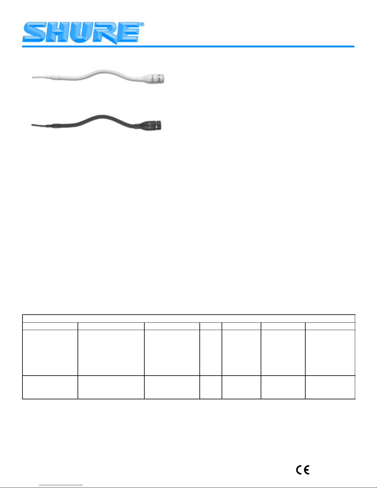
• MX202B/C, S, O: Black mini-condenser microphone;
includes cable, in-line preamplifier, and stand adapter.
• MX202W/C, S, O: White mini-condenser microphone;
includes cable, in-line preamplifier, and stand adapter.
• MX202BP/C, S, O: Black mini-condenser microphone;
includes cable and plate-mounted preamplifier.
• MX202WP/C, S, O : White mini-condenser microphone;
includes cable and plate-mounted preamplifier.
Cardioid (C). Recommended for general sound reinforce-
ment applications. Pickup angle (–3 dB) = 130°.
Supercardioid ( S). Recommended f or s ound reinforcement applications requiring n arrow or m ore distant c over age. Pickup angle (–3 dB) = 115°.
Omnidirectional (O). Recommended for recording or remote monitoring applications. Pickup angle = 360°.
FEATURES
•
Wide dynamic range and frequency response for accurate sound reproduction across the audio spectrum
•
Interchangeable cartridges that provide an optimal polar
pattern choice for each application
•
Balanced, transformerless output for increased immunity
to noise over long cable runs
•
Supplied stand-mount adapter for portable applications
(in-line preamplifier versions only)
•
White or black finish that blends unobtrusively with most
surroundings
MICROPHONE APPLICATION AND SELECTION GUIDE
Application Mounting Method Preamplifier Type Color Polar Pattern Model Cable length
Sound reinforcement
for choirs or theater
Ambience recording or
remote monitoring of
speech and vocals
Stand–mounted or sus-
pended from ceiling
Suspended from ceiling
Stand–mounted or sus-
pended from ceiling
Suspended from ceiling
In Line
In Line
In Line
In Line
Plate Mounted
Plate Mounted
Plate Mounted
Plate Mounted
In Line
In Line
Plate Mounted
Plate Mounted
GENERAL INSTALLATION GUIDELINES
1. For choir installations, hang a microphone 0.6 to 0.9 m
(2-3 ft.) in front of the first row, and 0.6 to 0.9 m (2 to 3
ft.) higher than the heads of the singers in the last row.
Aim the microphone at the back row (See Figure 1).
2. When miking groups that move or vary in size, use a
boom stand and the supplied stand adapter.
3. If four o r m ore m icrophones w ill b e o pen a t o nce, a n a utomatic mixer, s uch a s t he S hure S CM810 o r F P410, i s recommended. Set u p t he a utomatic m ixer so t hat all over-
head microphones gate on simultaneously.
Black
White
Black
White
Black
White
Black
White
Black
White
Black
White
Cardioid
Cardioid
Supercardioid
Supercardioid
Cardioid
Cardioid
Supercardioid
Supercardioid
Omnidirectional
Omnidirectional
Omnidirectional
Omnidirectional
MX202B/C
MX202W/C
MX202B/S
MX202W/S
MX202BP/C
MX202WP/C
MX202BP/S
MX202WP/S
MX202B/O
MX202W/O
MX202BP/O
MX202WP/O
9 m (30 ft.)
9 m (30 ft.)
2001, Shure Incorporated
27D2836 (AD)
Printed in Mexico

PREAMPLIFIER INSTALLATION
Installing the In-Line Preamplifier (FIGURE 2)
Use the two supplied mounting clamps to hold the preamplifier in place on a wall or ceiling. Set the length of the cable
by cutting it appropriately and using the screw terminal connections inside the preamplifier. The terminals are marked
B (black), R (red), and S (shield).
Plate-Mount Preamplifier Input Connections
1. Detach the preamplifier housing by removing the two
Phillips head screws from the back of the housing.
2. Remove the material from the hole in the center of the
cover plate or the center of the preamplifier housing.
3. Cut the cable to the desired hanging length, allowing for
a 76 mm to 101 mm (3 to 4 in.) service loop.
4. Clamp the strain relief around the cable and insert the
strain relief into the hole.
5. Connect the cable leads to the terminal block (B = Black,
R = Red, S = Shield).
Plate–Mount Preamplifier Output Cable Connections
1. Using p rofessional-quality, two-conductor, shielded m icro-
phone cable, thread the output cable from the outside of
the preamplifier through the hole with the black bushing.
2. Connect cable to pins as follows: Pin 2 = +, Pin 3 = –,
Shield = S.
3. Reattach the preamplifier housing.
MICROPHONE INSTALLATION (FIGURE 3)
The microphone is most s table w hen t he g ooseneck i s b ent
into a “lazy S” shape as shown in Figure 3. Use the supplied
hanging clip and heavy thread or monofilament fishing line to
suspend the microphone at a specific location.
INSTALLING THE FOAM WINDSCREEN (FIGURE 4)
1. Press the foam windscreen onto the microphone until it
snaps into the groove located behind the cartridge.
2. T o remove the windscreen, spread the gap in its mount-
ing ring with a screwdriver or thumbnail and pull the
windscreen off.
SPECIFICATIONS
Maximum SPL (1 kHz at 1% THD, 1 kΩ load)
Cardioid: 124.2 dB
Supercardioid: 122.7 dB
Omnidirectional:116.7 dB
Equivalent Output Noise (A-weighted)
Cardioid: 28.0 dB SPL
Supercardioid: 26.5 dB SPL
Omnidirectional:20.5 dB SPL
Signal to Noise Ratio (referenced at 94 dB SPL)
Cardioid: 66.0 dB
Supercardioid: 67.5 dB
Omnidirectional:73.5 dB
Dynamic Range at 1 kΩ Load
96.2 dB
Common Mode Rejection
45.0 dB minimum
Preamplifier Output Clipping Level (1% THD)
–6.0 dBV (0.5 V)
Polarity
Positive sound pressure on diaphragm produces positive
voltage on pin 2 relative to pin 3 of output connector.
Power Requirements
11 to 52 Vdc phantom, 2.0 mA
Environmental Requirements
Operating Temperature Range: –18° C to 57° C (0° F to
135° F)
Relative Humidity: 0 to 95%
Dimensions (FIGURE 7)
CERTIFICATION
Eligible to bear CE Marking. Conforms to European EMC
Directive 89/336/EEC. Meets applicable tests and performance criteria in European Standard EN55103 (1996) parts
1 and 2, for residential (E1) and light industrial (E2) environments.
NOTE: For technical data by fax, phone 1-800-488-3297
and follow the recorded instructions. For additional technical assistance, phone Shure at (847) 866-2200. In Europe,
phone 49-7131-72140.
Shure, the Shure logo, and Microflex
are registered trade-
marks of Shure Incorporated.
Frequency Response (FIGURE 5)
50 to 17,000 Hz
Polar Pattern (FIGURE 6)
Output Impedance
EIA Rated at 150 Ω (180 Ω actual)
Sensitivity (At 1,000 Hz, open circuit voltage*)
Cardioid: –35.0 dBV/Pa (17.8 mV)
Supercardioid: –33.5 dBV/Pa (21.1 mV)
Omnidirectional: –27.5 dBV/Pa (42.2 mV)
*1 Pascal = 94 dB SPL
REPLACEMENT PARTS
Omnidirectional Cartridge (Black) R183B. . . . . . . . . . . . .
Omnidirectional Cartridge (White) R183W. . . . . . . . . . . .
Supercardioid Cartridge (Black) R184B. . . . . . . . . . . . . . .
Supercardioid Cartridge (White) R184W. . . . . . . . . . . . . .
Cardioid Cartridge (Black) R185B. . . . . . . . . . . . . . . . . . . .
Cardioid Cartridge (White) R185W. . . . . . . . . . . . . . . . . . .
Snap-Fit Windscreens (Black, 4 per pkg.) RK183WS. . .
Preamplifier kit, plate mounted RK202PK. . . . . . . . . . . . . .
Stand Adaptor 65B1752. . . . . . . . . . . . . . . . . . . . . . . . . . . .
2

MICROPHONE SUSPENDU MICROFLEX SÉRIE
MX200
GUIDE DE L’UTILISATEUR
GÉNÉRALITÉS
Les Shure Microflex
série MX200 sont des microphones
électrostatiques conçus pour la prise de son de choeurs et
groupes vocaux. Ils s ont e n g énéral s uspendus a u–dessus d e
la tête des artistes. Leur haute sensibilité et large gamme de
fréquence permettent de les utiliser pour les enregistrements
et la sonorisation de s cène. U n c o l d e c ygne i ntégré d e 1 0 c m
permet de les orienter facilement vers la source sonore.
AVANTAGES
•
Large gamme d ynamique e t courbe de r éponse p our u ne
reproduction précise du son sur tout le spectre audio
•
Cartouches interchangeables permettant une courbe
de directivité optimale pour chaque application
•
Sortie équilibrée sans transformateur pour une immunité aux bruits accrue avec de grandes longueurs de fil.
•
Adaptateur de pied inclus permettant l’utilisation à la
main (versions à préampli en ligne seulement)
•
Fini noir ou blanc assurant la discrétion dans la plupart
des décors
VARIANTES
Tous les microphones Microflex sont offerts avec l’une
des trois cartouches interchangeables. La courbe de directivité de la cartouche utilisée dans un micro particulier est indiquée par le suffixe du numéro de modèle :
C = Cardioïde, S = Supercardioïde, O= Omnidirectionnelle
MX202B/C, S, O : Mini microphone électrostatique noir
avec câble, préampli et adaptateur de pied.
MX202W/C, S, O : Mini microphone électrostatique blanc
avec câble, préampli et adaptateur de pied.
MX202BP/C, S, O : Mini microphone électrostatique noir
avec câble et préampli monté sur plaque.
MX202WP/C, S, O : Mini microphone électrostatique
blanc avec câble et préampli monté sur plaque.
Cardioïde (C). Recommandé pour les applications de so-
norisation générale. Angle de captage (–3 dB) = 130.
Supercardioïde (S). Recommandé pour les applications
de sonorisation exigeant un captage plus étroit ou à plus
grande distance. Angle de captage (–3 dB) = 115.
Omnidirectionnel (O). R ecommandé pour l’enregistrement
ou le captage à distance. Angle de captage = 360.
DIRECTIVES GÉNÉRALES POUR L’INSTALLATION
(FIGURE 1)
1. Pour la prise de son des choeurs, suspendre un micropho-
ne à 60 à 90 cm au-dessus du premier rang et à 60 à 90
cm au-dessus de la tête des choristes du dernier rang.
Orienter le microphone vers le dernier rang (voir figure 1).
2. Pour la prise de son de groupes mobiles ou variables en
nombre, utiliser une girafe et l’adaptateur de pied fourni.
3. Lorsque quatre microphones ou plus doivent être ouverts
simultanément l’usage d’une table de mélange automatique, telle que la Shure SCM810 ou FP410 est recommandé. Régler la table de mélange de façon à ce que tous les
microphones suspendus soient activés simultanément.
INSTALLATION DU PRÉAMPLI
Installation du préampli en ligne (FIGURE 2)
Fixer le microphone sur un mur ou un plafond à l’aide des
deux pinces de montage f ournies. C ouper le c âble à la longueur
voulue et le brancher sur les bornes à vis de l’intérieur du
préampli. Les bornes sont marquées B (noir), R (rouge) et S
(blindage).
Branchement d’entrée du préampli monté sur plaque
1. Retirer les deux vis Phillips au dos du boîtier du préampli
pour le détacher.
2. Ouvrir le trou pré-perforé du centre du couvercle ou du
boîtier du préampli.
3. Couper le câble à la longueur voulue en prévoyant 8 à
10 cm supplémentaire pour former une boucle.
4. Refermer le soulagement de traction sur le câble et l’in-
sérer dans le trou.
5. Brancher les fils du c âble s ur le b ornier ( B = n oir, R = r ouge,
S = Blindage).
GUIDE DE SÉLECTION ET D’APPLICATION DES MICROPHONES
Application Méthode de
Sonorisation de
choeurs ou de
théâtre
Enregistrement
d’ambiance ou
contrôle à
distance de la
voix
montage
Sur pied ou
suspendu au
plafond
Suspendu au
plafond
Sur pied ou
suspendu au
plafond
Suspendu au
plafond
Micros à préampli Couleur Courbe de directivité Modèle Longueur
En ligne
En ligne
En ligne
En ligne
Monté sur plaque
Monté sur plaque
Monté sur plaque
Monté sur plaque
En ligne
En ligne
Monté sur plaque
Monté sur plaque
Noir
Blanc
Noir
Blanc
Noir
Blanc
Noir
Blanc
Noir
Blanc
Noir
Blanc
du câble
Cardioïde
Cardioïde
Supercardioïde
Supercardioïde
Cardioïde
Cardioïde
Supercardioïde
Supercardioïde
Omnidirectionnelle
Omnidirectionnelle
Omnidirectionnelle
Omnidirectionnelle
3
MX202B/C
MX202W/C
MX202B/S
MX202W/S
MX202BP/C
MX202WP/C
MX202BP/S
MX202WP/S
MX202B/O
MX202W/O
MX202BP/O
MX202WP/O
9 m
9 m

Branchement du câble de sortie du préampli monté
sur plaque
1. Utiliser un câble de microphone blindé à deux conducteurs, de q ualité p rofessionnelle. I nsérer l e c âble d e l ’extérieur du préampli, dans le trou muni d’une bague noire.
2. Brancher le câble comme suit : Broche 2 = +, Broche
3 = –, Blindage = S.
3. Remonter le boîtier du préampli.
INSTALLATION DU MICROPHONE (FIGURE 3)
La meilleure stabilité du micro est obtenue avec le col de
cygne courbé en forme de ”S” allongé, comme illustré à la
figure 3. Suspendre le microphone à l’endroit désiré au
moyen du clip fourni et d’un cordon ou d’un fil de pêche monofilament solide.
INSTALLATION DU COUPE–VENT EN MOUSSE
(FIGURE 4)
1. Enfoncer le coupe-vent en mousse sur le microphone
jusqu’à ce qu’il s’encliquette dans la gorge se trouvant
derrière la cartouche.
2. Pour le retirer, écarter les extrémités de la bague de
montage avec un tournevis ou une punaise et le dégager du micro.
CARACTÉRISTIQUES
Courbe de réponse (FIGURE 5)
50 à 17 000 Hz
Courbe de directivité (FIGURE 6)
Impédance de sortie
EIA nominale 150 ohms (180 ohms réels)
Sensibilité en circuit ouvert (à 1000 Hz réf. 1V/Pascal*)
Cardioïde : –35,0 dBV/Pa (17,8 mV)
Supercardioïde : –33,5 dBV/Pa (21,1 mV)
Omnidirectionnel : –27,5 dBV/Pa (42,2 mV)
*1 Pascal = 94 dB NPA
NPA maximum (1 kHz avec DHT de 1 %, charge de 1 K)
Cardioïde : 124,2 dB
Supercardioïde : 122,7 dB
Omnidirectionnel : 116,7 dB
Bruit de sortie équivalent (pondération en A)
Cardioïde : 28,0 dB NPA
Supercardioïde : 26,5 dB NPA
Omnidirectionnel : 20,5 dB NPA
Rapport signal/bruit (mesuré avec une pression
acoustique de 94 dB)
Cardioïde : 66,0 dB
Supercardioïde : 67,5 dB
Omnidirectionnel : 73,5 dB
Gamme dynamique avec charge de 1 k
96,2 dB
Rejet en mode commun
45,0 dB au minimum
Niveau d’écrêtage de sortie préampli (1 % DHT)
–6,0 dBV (0,5 V)
Polarité
Une pression acoustique positive sur le diaphragme
produit une tension positive sur la broche 2 par rapport à
la broche 3 du connecteur de sortie.
Alimentation
11 à 52 V c.c. duplex, 2,0 mA
Environnement
Plage de températures de fonctionnement : –18 à 57C
Humidité relative : 0 à 95%
Dimensions (Figure 7)
Homologation
Autorisé à porter la marque CE. Conforme à la directive
CEM européenne 89/336/CEE. Conforme aux critères applicables de test et de performances de la norme européenne EN 55103 (1996) parties 1 et 2 pour les environnements
résidentiels (E1) et d’industrie légère (E2).
REMARQUE : Pour toute information technique par télécopie, composer le 1–800–488–3297 et suivre les instructions de l’enregistrement. Pour toute assistance technique supplémentaire, appeler Shure au (847) 866–2200.
En Europe, appeler le 49–7131–72140.
PIÈCES DE RECHANGE
Cartouche omnidirectionnelle (noire) R183B. . . . . . . . . . .
Cartouche omnidirectionnelle (blanche) R183W. . . . . . .
Cartouche Supercardioïde (noire) R184B. . . . . . . . . . . . .
Cartouche Supercardioïde (blanche) R184W. . . . . . . . . .
Cartouche cardioïde (noire) R185B. . . . . . . . . . . . . . . . . . .
Cartouche cardioïde (blanche) R185W. . . . . . . . . . . . . . .
Kit de préampli, monte sur plaque RK202PK. . . . . . . . . .
Adaptateur de pied 65B1752. . . . . . . . . . . . . . . . . . . . . . . .
4

GEBRAUCHSANLEITUNG FÜR MICROFLEX
OVERHEAD–MIKROFONE DER REIHE MX200
ALLGEMEINES
Shure Microflex
Mikrofone der Reihe MX200 sind
Mini–Elektretkondensatormikrofone, die zur Aufnahme von
Chören und aufführenden Gruppen vorgesehen sind.
Üblicherweise hängen sie über den Köpfen der Aufführenden
herab. Durch ihre hohe Empfindlichkeit und den breiten
Frequenzbereich eignen sie sich zu Aufzeichnungszwecken
sowie für Tonverstärkungsanwendungen. Ein daran
befestigter 10 cm langer Schwanenhals ermöglicht ihre
einfache Ausrichtung auf die Schallquelle.
MERKMALE
•
Breiter Dynamikbereich und Frequenzgang für genaue
Tonwiedergabe über das gesamte Tonfrequenzspektrum hinweg
•
Austauschbare Kapseln, die ein optimales Polarmuster
für jeden Verwendungszweck ermöglichen
•
Ausgeglichene, transformatorlose Ausgabe für erhöhte
Rauschunempfindlichkeit bei langen Kabelführungen
•
Mitgelieferter Adapter zur Stativbefestigung für tragbare
Anwendungen (nur bei In-line-Vorverstärkerausführungen)
•
Weiße oder schwarze Oberfläche, die sich unauffällig in
die meisten Umgebungen einfügt
VARIANTEN
Alle Microflex-Mikrofone sind mit einer von drei
austauschbaren Kapseln lieferbar. Das Polarmuster der
Kapsel wird durch das Modellnummer–Suffix angegeben.
C = Kardioid, S = Superkardioid, O= Alle Richtungen
• MX202B/C, S, O: Schwarzes Mini-Kondensatormikro-
fon, einschließlich Kabel, In-line-Vorverstärker und Stativadapter.
• MX202W/C, S, O: Weißes Mini-Kondensatormikrofon, ein-
schließlich Kabel, In-line-Vorverstärker und Stativadapter.
• MX202BP/C, S , O : Schwarzes Mini-Kondensatormikro-
fon, einschließlich Kabel und plattenmontiertem Vorverstärker.
• MX202WP/C, S, O: Weißes Mini-Kondensatormikrofon,
einschließlich Kabel und plattenmontiertem Vorverstärker.
Kardioid (C). Für allgemeine
Tonverstärkungsanwendungen empfohlen.
Ansprechwinkel (–3 dB) = 130.
Superkardioid (S). Für Tonverstärkungsanwendungen
empfohlen, die eine engere oder weiter entfernte
Abdeckung erfordern. Ansprechwinkel (–3 dB) = 115.
Alle Richtungen (O). Für Aufzeichnungs- oder
Fernüberwachungsanwendungen empfohlen.
Ansprechwinkel = 360.
ALLGEMEINE INSTALLATIONSRICHTLINIEN
1. Für Choraufnahmen ein M ikrofon k napp e inen M eter v or
der ersten Reihe und k napp 1 M eter höher a ls d ie K öpfe
der Sänger i n d er l etzten R eihe a ufhängen. D as Mikrofon
auf die hintere Reihe richten (siehe Abbildung 1).
2. Bei Aufnahme von Gruppen, die sich bewegen oder ver-
änderlich groß sind, einen Galgenständer und den mitgelieferten Adapter verwenden.
3. Wenn vier oder mehr Mikrofone gleichzeitig verwendet
werden sollen, ist d er E insatz e iner a utomatischen M ischstufe, wie z.B. S hure SCM810 oder F P410, zu e mpfehlen.
Die automatische Mischstufe s o einstellen, d aß alle Overhead–Mikrofone gleichzeitig angesteuert werden.
INSTALLATION DES VORVERSTÄRKERS
Installation des In-line-Vorverstärkers (ABBILDUNG 2)
Den Vorverstärker mit Hilfe der beiden mitgelieferten
Montageschellen an einer Wand oder Decke befestigen.
Die Länge des Kabels anpassen, indem es zweckmäßig
zugeschnitten wird, und dieses mit Hilfe der
Schraubklemmenanschlüsse innerhalb des Vorverstärkers
anschließen. Die Anschlußklemmen sind mit B (Schwarz),
R (Rot) und S (Abschirmung) markiert.
EINGANGSANSCHLÜSSE DES
PLATTENMONTIERTEN VORVERSTÄRKERS
1. Das Vorverstärkergehäuse abnehmen, indem die bei-
den Kreuzschlitz-Kopfschrauben aus der Rückseite des
Gehäuses herausgeschraubt werden.
2. Das Material aus der Öffnung in der Mitte der Abdeckplatte
oder aus der Mitte des Vorverstärkergehäuses entfernen.
3. Das Kabel auf die gewünschte Distanzlänge zuschnei-
den und dabei einen 8-10 cm langen Wartungsknoten
berücksichtigen.
4. Die Zugentlastung um das Kabel klemmen und in die
Öffnung einführen.
5. Die Kabelleitungen an die Klemmleiste anschließen (B =
Schwarz, R = Rot, S = Abschirmung).
5
 Loading...