

Page 1

UHF Wireless System
USER GUIDE SUPPLEMENT
MD (800–820 MHz )
CONTENTS
SPECIFICATIONS 2. . . . . . . . . . . . . . . . . . . . . . . . . . . . . . . . . . . . . . . . . . . . . .
FURNISHED ACCESSORIES 5. . . . . . . . . . . . . . . . . . . . . . . . . . . . . . . . . . . .
OPTIONAL ACCESSORIES 6. . . . . . . . . . . . . . . . . . . . . . . . . . . . . . . . . . . . . .
REPLACEMENT PARTS 6. . . . . . . . . . . . . . . . . . . . . . . . . . . . . . . . . . . . . . . .
UHF WIRELESS SYSTEM COMPATIBILITY GUIDE 7. . . . . . . . . . . . . . . .
MASTER LIST 8. . . . . . . . . . . . . . . . . . . . . . . . . . . . . . . . . . . . . . . . . . . . . . . . . .
2001, Shure Incorporated
27B8667 (AA)
Printed in U.S.A.
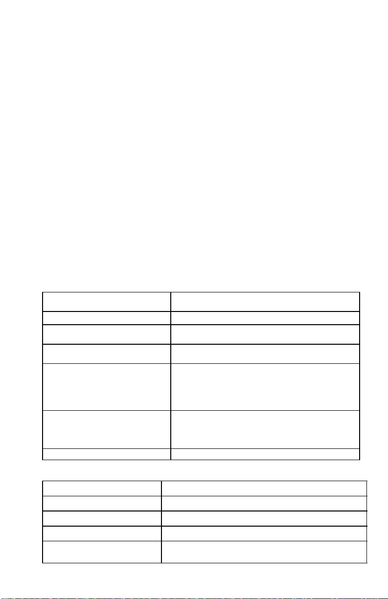
Page 2

SPECIFICATIONS
RF Carrier Frequency Range
800–820 MHz
Working Range
U1, U2: 152.4 m, minimum, under typical conditions; 487.6 m line of sight
U1H: 275 m, minimum, under typical conditions; 975 m line of sight
NOTE: Actual working range depends on RF signal absorption, reflection and
interference
Audio Frequency Response
50 to 15,000 Hz, ±2 dB. NOTE: Overall system frequency response depends on the
microphone element
Gain Adjustment Range
U1, U1H: 0 to 40 dB
U2: 0 to 26 dB
Modulation
±45 kHz deviation compressor-expander system with pre-and de-emphasis
RF Power Output
U1, U2: 10 mW maximum
U1H: 50 mW maximum
Dynamic Range
>102 dB, A-weighted
RF Sensitivity
U4S U4D
–110 dBm
12 dB SINAD
–105 dBm
30 dB SINAD
Image Rejection
90 dB typical
Spurious Rejection
75 dB typical
Ultimate Quieting (ref. 45 kHz deviation)
>100 dB, A-weighted
Audio Polarity
Positive pressure on microphone diaphragm (or positive voltage applied to tip of
WA302 phone plug) produces positive voltage on pin 2 with respect to pin 3 of
low impedance output and the tip of the high impedance
System Distortion (ref. ±45 kHz deviation, 1 kHz modulation)
0.3% Total Harmonic Distortion typical
Power Requirements
U1, U1H, U2: 1.5V AA alkaline battery (Duracell MN1500 recommended); Nicad
optional
U4: 90 to 230 Vac , 50/60 Hz
Power Consumption:
U4S: 9.6 W min., 13.2 W max.
U4D: 12 W min.,16 W max.
UA840: 15 W min., 16 W max.
Battery Life (Typical)
U1, U2: 12 hours (with Duracell MN1500 1.5V AA alkaline battery)
U1H: 6 hours (with Duracell MN1500 1.5V AA alkaline battery)
–107 dBm
12 dB SINAD
–102 dBm
30 dB SINAD
1
/4-inch output
2
Page 3
Operating Temperature Range
-20° to 50° C NOTE: Battery characteristics may limit this range
Overall Dimensions
U1: 92.2 mm L x 64.7 mm W x 24.2 mm D
U2/58:254 mm L x 50.8 mm Dia.
U2/BETA 58: 254 mm L x 53.2 mm Dia.
U2/87:228.6 mm x 49.2 mm Dia.
U2/BETA 87: 216 mm L x 50.8 mm Dia
U4S/U4D: 44.5 mm H x 482.6 mm W x 295.3 mm D
Net Weight
U1, U1H: 175.2 g without battery
U2/58, U2/BETA 58: 375.6 g without battery
U2/87, U2/BETA 87: 303.1 g without battery
U4S: 3.30 kg
U4D: 3.85 kg
Certification
U1*, U2: BAPT Type Approved to FTZ 17TR 2019 and BAPT 122 R1; EMC
Approved to ETS 300 445.
U4S, U4D: VDE Certified to EN 60 950. BAPT Type Approved to FTZ 17TR 2019
and BAPT 122 R1; EMC Approved to ETS 300 445. Meets Low Voltage
Directive.
UHF Type Approved and EMC Approved systems are eligible to carry the CE
marking.
*The U1H transmitter does not carry the same approvals as the U1 transmitter.
U1, U1H Transmitter Input
Connector:
Input Configuration:
Actual Impedance:
Maximum Input Level:
6 Vp–p (+7 dBV) for 1% THD at minimum gain
Switchcraft TA4F Tini Q-G or
LEMO connector (optional)
Unbalanced, active
18 kΩ with lavalier microphone
1 MΩ with instrument cable
setting using 1 kHz signal.
Pin 1: Tied to Ground
TA4F Tini Q.G. Connector Pin
Assignments:
Pin 4: Tied thru 20kΩ Resistor to Ground.
Pin 2: Tied to +5 V
Pin 3: Tied to Audio
(On instrument adapter cable, Pin 4 floats)
Pin 1: Tied to Pin 3 and 10 kΩ to Ground
LEMO Connector
Pin Assignments:
Pin 2: +5V
Pin 3: Tied to Pin 1
Pin 4: Tied to Shield (Ground for Positive Bias)
Voltage for Remote Power:
+5 V supplied to microphone cartridge
U1, U1H Transmitter Output (Figure 1)
Connector:
Actual Impedance:
Nominal Output Level:
Maximum Output Level:
Pin Assignments:
+10 dBm (+17 dBm for U1H)
+1 1 dBm (+18 dBm for U1H)
3
SMC
50 Ω
Shell = Ground
Center = Signal
Page 4
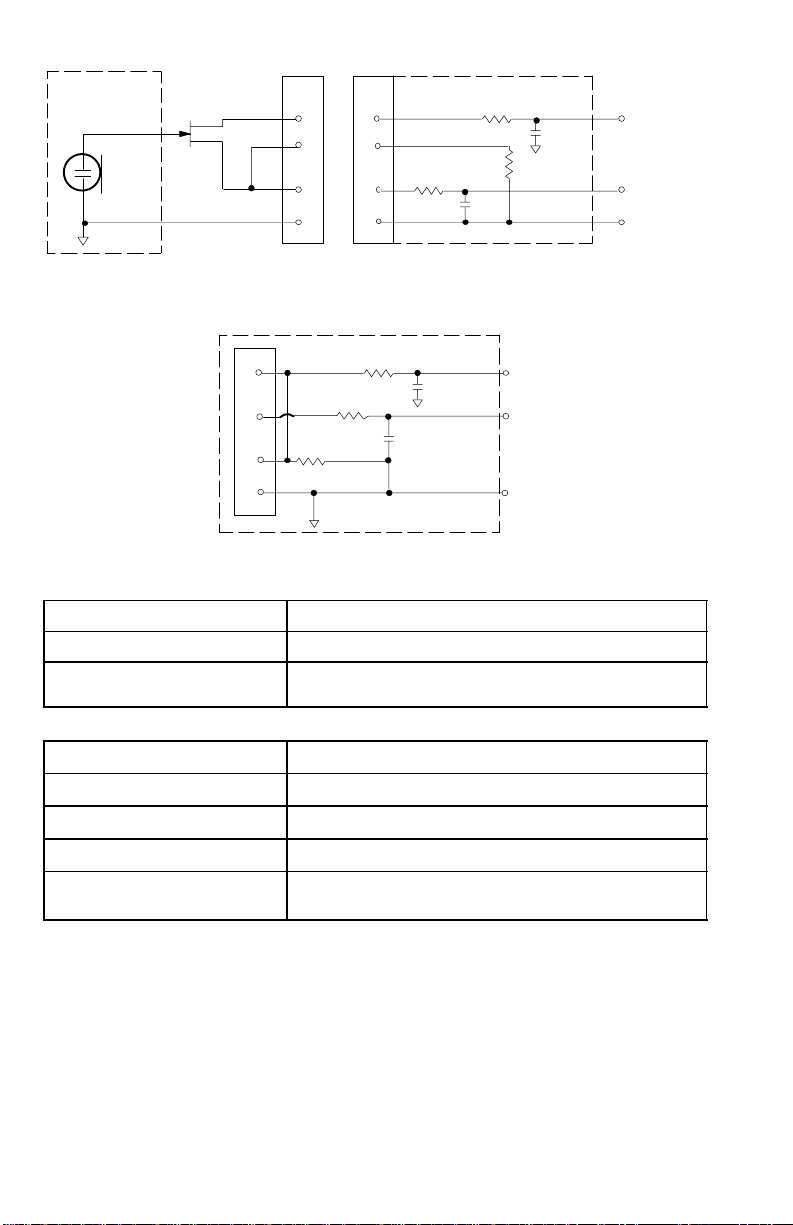
MICROPHONE
ELEMENT
NOTE: LAVALIER MIC TIES PINS 3 AND 4
TOGETHER; GUITAR CABLE DOES NOT.
U1/U1H MIC JACK BOARD
2
2
4
4
500 Ω
3
3
1
U1L (LEMO 4 PIN) MIC JACK BOARD
1
500 Ω
27 pF
20K Ω
27 pF
+5 V
AUDIO
GROUND
1
2
10K Ω
3
4
499 Ω
499 Ω
AUDIO
27 pF
BIAS
27 pF
SHIELD
FIGURE 1
U2 Transmitter Input
Input Configuration: Unbalanced, active
Actual Impedance: 20 kΩ
Maximum Input Level: 3 Vp–p (0.5 dBV) for 1% THD at minimum gain setting
using 1 kHz signal.
U2 Transmitter Output
Connector:
Actual Impedance:
Nominal Output Level:
Maximum Output Level:
Pin Assignments:
SMC
50 Ω
+10 dBm
+11 dBm
Shell = Ground
Center = Signal
4
Page 5

U4S and U4D Receiver Input
Connector: Antenna Power Input Network Interface
Connector T ype: BNC IEC 25–Pin D
Actual Impedance: 50 Ω –– ––
Nominal Input
Level:
Maximum Input
Level:
–95 to –30 dBm 90–230 V AC,
50/60 Hz
+6 dBm
230 VAC, 50/60 Hz ––
(–20 dBm
CMOS Logic
recommended)
Pin Assignments: Shell = Ground
IEC Standard ––
Center = Signal
Voltage for
Remote Power:
12 Vdc, 150 mA
maximum
–– 5V, 700 mA max.
U4S and U4D Receiver Output
Connector: Monitor Power
Output
Configuration:
Actual
Impedance:
Nominal
Input Level:
Pin
Assignments:
Unbalanced
mono, 1/4 inch
300 Ω –– 1 kΩ 30 Ω See
–– 90 to 230
Tip = Hot
Ring = Hot
Output
–– Un-
VAC, 5A
IEC
Standard
Sleeve = Gnd
Voltage/
Current/
Phantom
Power
Protection?
*Output Level: Microphone Level = Line Level – 30 dB
Yes –– Yes Yes 5V, 700 mA
High Z
Audio
Low Z
Audio*
Balanced See
balanced
–– –– CMOS
Tip = Hot
Ring/
Sleeve =
1 = Ground
2 = Hot
3 = Hot
Gnd
Network
Interface
Appendix
Appendix
Appendix
resettable
polyfuse
FURNISHED ACCESSORIES
Microphone Stand Adapter (U2) WA370A. . . . . . . . . . . . . . . . . . . . . . . . . . . . . . . . . . .
Zipper Bag (U1) 26A13. . . . . . . . . . . . . . . . . . . . . . . . . . . . . . . . . . . . . . . . . . . . . . . . . . .
Zipper Bag (U2) 26A14. . . . . . . . . . . . . . . . . . . . . . . . . . . . . . . . . . . . . . . . . . . . . . . . . . .
Screwdriver 80A498. . . . . . . . . . . . . . . . . . . . . . . . . . . . . . . . . . . . . . . . . . . . . . . . . . . . .
Coaxial Antenna Cable (2 ft) UA802. . . . . . . . . . . . . . . . . . . . . . . . . . . . . . . . . . . . . . . .
1/2 Wave Antenna UA820A. . . . . . . . . . . . . . . . . . . . . . . . . . . . . . . . . . . . . . . . . . . . . . . .
Transmitter Carrying Case 65A8257. . . . . . . . . . . . . . . . . . . . . . . . . . . . . . . . . . . . . . . .
Carrying Case Insert 29B1577. . . . . . . . . . . . . . . . . . . . . . . . . . . . . . . . . . . . . . . . . . . . .
Logic
See
5
Page 6

OPTIONAL ACCESSORIES
Instrument Adapter Cable (U1) WA302. . . . . . . . . . . . . . . . . . . . . . . . . . . . . . . . . . . . . .
Switchcraft TA4F Female 4–Pin Connector (U1) WA330. . . . . . . . . . . . . . . . . . . . . . . .
In-Line Audio Switch (U1) WA360. . . . . . . . . . . . . . . . . . . . . . . . . . . . . . . . . . . . . . . . . . .
1.8 Meter (6 ft) Receiver-Mixer Cable (1/4” phone to XLR) WA410. . . . . . . . . . . . . . . .
7.6 Meter (25 ft) Antenna Extension Cable UA825. . . . . . . . . . . . . . . . . . . . . . . . . . . .
15.2 (50 ft) Meter Antenna Extension Cable UA850. . . . . . . . . . . . . . . . . . . . . . . . . . .
In–Line Active Remote Antenna Kit (800 – 830 MHz) UA830C. . . . . . . . . . . . . . . . . .
Antenna/Power Distribution System, 230 Vac UA845MB. . . . . . . . . . . . . . . . . . . . . . .
Directional Antenna UA870MB. . . . . . . . . . . . . . . . . . . . . . . . . . . . . . . . . . . . . . . . . . . . .
REPLACEMENT PARTS
Hardware Kit (screwdriver, mounting feet, cable clamps) 90VL1371. . . . . . . . . . . . .
Bulkhead Adapters for Front–Mounting Antennas 95A8647. . . . . . . . . . . . . . . . . . . .
230 VAC Power Cord (Schuko mains connector) 95A8247. . . . . . . . . . . . . . . . . . . . .
304 mm (12 in.) Daisy–Chain Power Cord (230 V) 95A8678. . . . . . . . . . . . . . . . . . . .
SM58 Cartridge with Grille (U2/58) R158. . . . . . . . . . . . . . . . . . . . . . . . . . . . . . . . . . . .
BETA 58A Cartridge with Grille (U2/BETA 58) R179. . . . . . . . . . . . . . . . . . . . . . . . . . .
SM87 Cartridge with Grille (U2/87) R165. . . . . . . . . . . . . . . . . . . . . . . . . . . . . . . . . . . .
BETA 87 Cartridge with Grille (U2/BETA 87) R166. . . . . . . . . . . . . . . . . . . . . . . . . . . .
Matte Silver Grille (U2/58) RK143G. . . . . . . . . . . . . . . . . . . . . . . . . . . . . . . . . . . . . . . . . .
Matte Silver Grille (U2/BETA 58) RK265G. . . . . . . . . . . . . . . . . . . . . . . . . . . . . . . . .
Matte Silver Grille (U2/BETA 87 RK313G. . . . . . . . . . . . . . . . . . . . . . . . . . . . . . . . . .
Black Grille (U2/87) RK214G. . . . . . . . . . . . . . . . . . . . . . . . . . . . . . . . . . . . . . . . . . . . . . .
Black Grille (U2/BETA 58) RK323G. . . . . . . . . . . . . . . . . . . . . . . . . . . . . . . . . . . . . . . . . .
Black Grille (U2/BETA 87) RK324G. . . . . . . . . . . . . . . . . . . . . . . . . . . . . . . . . . . . . . . . . .
Belt Clip (U1) 53A8247A. . . . . . . . . . . . . . . . . . . . . . . . . . . . . . . . . . . . . . . . . . . . . . . . . .
Antenna (U1) 95A8646. . . . . . . . . . . . . . . . . . . . . . . . . . . . . . . . . . . . . . . . . . . . . . . . . . .
Antenna (U2) 95A2029. . . . . . . . . . . . . . . . . . . . . . . . . . . . . . . . . . . . . . . . . . . . . . . . . . .
6
Page 7

FREQUENCY SELECTION GUIDE
H
A
N
E
L
The Shure UHF Wireless System is designed for maximum flexibility and versatility in a variety of applications. Up to 19 Shure UHF Wireless Systems can be
operated simultaneously in a single installation using the frequency compatibility
groups. Please contact Shure Brothers Incorporated if you need additional information or assistance in frequency selection and setup.
Compatibility Groups
The Shure UHF Wireless System includes 12 groups of compatible channels. If you
are using more than one receiver in the same area, we recommend that you set the
receivers to different frequencies within the same group.
Compatible Frequency List
The following table lists the frequencies in each of the twelve compatibility
groups.
GROUP
GRP 1 GRP 2 GRP 3 GRP 4 GRP 5 GRP 6 GRP 7 GRP 8 GRP 9 GRP 10 GRP 11 GRP 12
1 800,375 800,375 800,500 800,475 800,225 801.300 800,600 800.400 800.800 800.100 800.100 800.100
2 801,500 801,625 801,750 801,350 800,850 803.100 801.600 801.100 801.300 800.700 800.700 800.700
3 802,000 802,375 802,500 801,975 801,725 803.700 802.100 802.600 802.600 801.900 801.600 801.900
C
4 802,875 803,375 803,500 803,225 802,225 804.600 802.900 803.300 803.300 802.500 802.200 802.800
5 804,000 804,125 804,250 805,600 802,975 805.200 803.300 804.400 804.900 803.400 803.400 803.400
H
6 804,500 804,625 804,750 806,475 803,975 806.400 805.700 805.100 806.200 804.000 804,000 804.600
A
7 805,750 805,375 805,500 806,975 805,350 807.000 806.500 806.500 806.800 805.200 804.900 805.200
8 806,750 807,125 807,250 807,725 805,975 808.500 807.000 807.300 807.800 805.800 805.500 808.200
N
9 807,250 808,125 808,250 808,725 807,475 812.100 807.800 810.700 813.400 808.800 808.500 808.800
10 808,375 808,625 808,750 810,225 809,350 813.000 810.400 811.600 814.000 809.400 810.000 810.000
E
11 809,250 809,375 809,500 811,225 812,975 813,600 814.600 813.100 815.200 810.600 810.600 810.600
L
12 809,750 809,875 810,000 814,475 813,850 814.800 815.400 813.800 815.800 811.200 811.800 811.500
13 813,375 811,375 811,500 815,225 814,350 815.400 815.900 815.200 816.700 812.100 812.400 812.100
14 816,000 813,625 813,750 815,725 815,475 816.300 816.700 817.800 817.900 812.700 813.300 813.300
15 817,250 816,125 816,250 816,475 816,225 818.400 818.300 818.400 818.500 813.900 813.900 813.900
16 817,750 816,625 817,750 817,475 817,350 819.300 819.500 819.400 819.700 814.500 817.500 818.700
17 818,875 817,625 819,000 818,225 818,975
18 819,750 818,875 819,775 819,475 819,725
19 819,875
7
Page 8

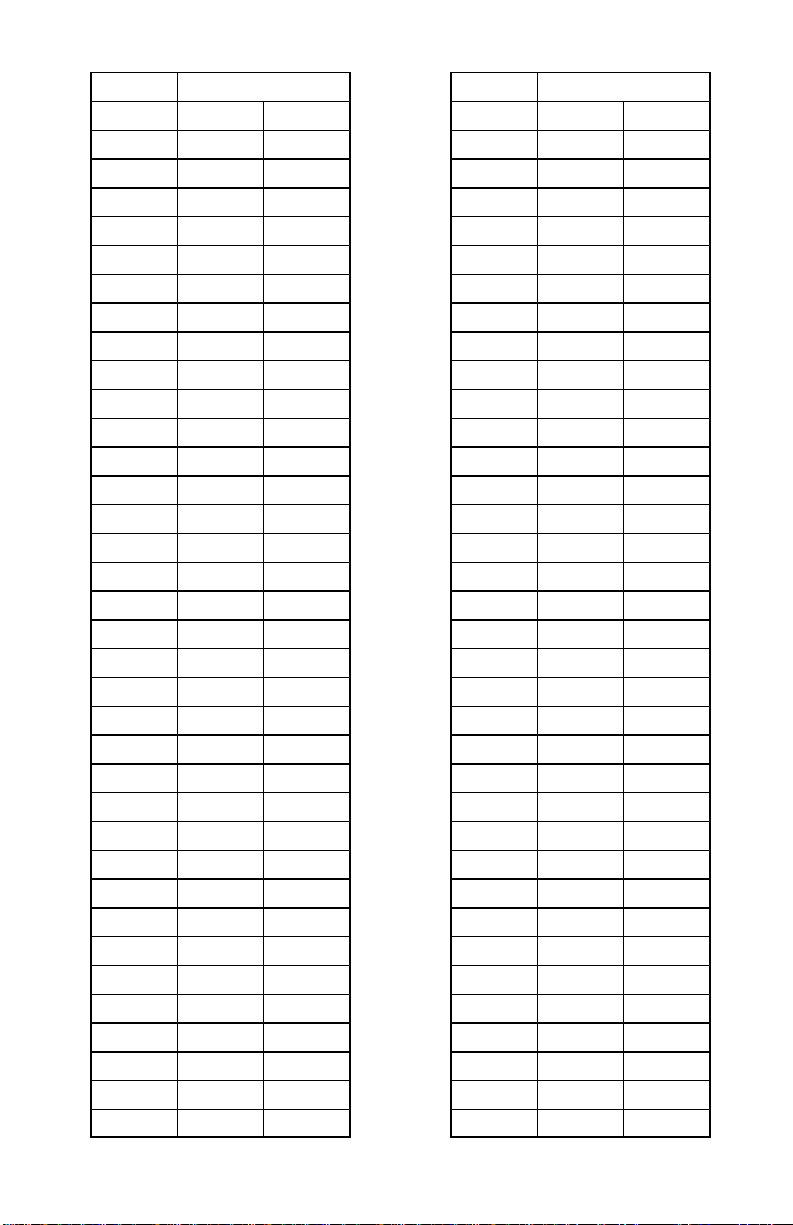
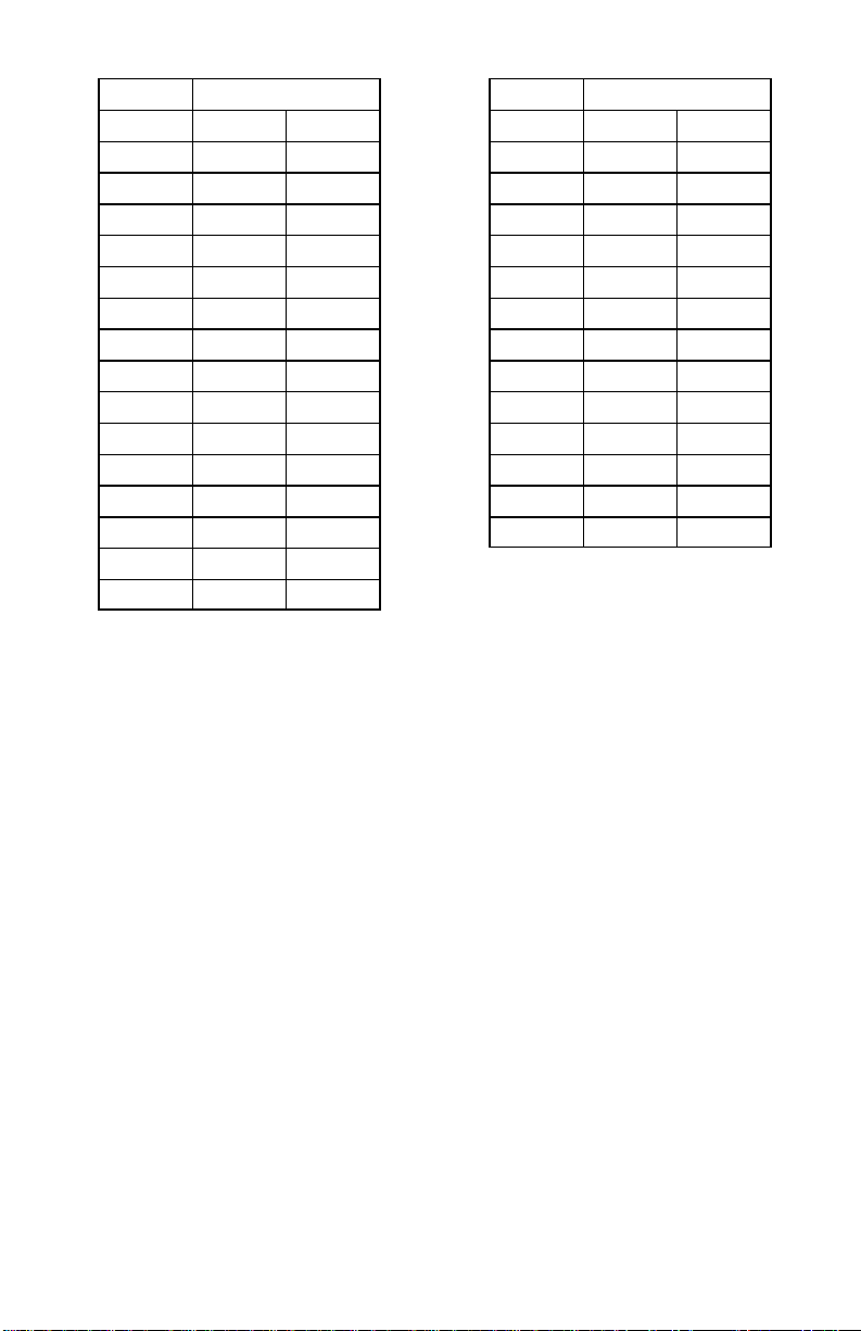
Master Frequency List
The Master List (Groups A1 through A8) covers all frequencies in 25 kHz
increments within the 800 to 820 MHz band.
MASTER
FREQ. GRP. CHAN.
800.100 A1 1
800.125 A1 2
800.150 A1 3
800.175 A1 4
800.200 A1 5
800.225 A1 6
800.250 A1 7
800.275 A1 8
800.300 A1 9
800.325 A1 10
800.350 A1 11
800.375 A1 12
800.400 A1 13
800.425 A1 14
800.450 A1 15
800.475 A1 16
800.500 A1 17
800.525 A1 18
800.550 A1 19
800.575 A1 20
800.600 A1 21
800.625 A1 22
800.650 A1 23
800.675 A1 24
800.700 A1 25
800.725 A1 26
800.750 A1 27
800.775 A1 28
800.800 A1 29
800.825 A1 30
800.850 A1 31
800.875 A1 32
MASTER
FREQ. GRP. CHAN.
800.900 A1 33
800.925 A1 34
800.950 A1 35
800.975 A1 36
801.000 A1 37
801.025 A1 38
801.050 A1 39
801.075 A1 40
801.100 A1 41
801.125 A1 42
801.150 A1 43
801.175 A1 44
801.200 A1 45
801.225 A1 46
801.250 A1 47
801.275 A1 48
801.300 A1 49
801.325 A1 50
801.350 A1 51
801.375 A1 52
801.400 A1 53
801.425 A1 54
801.450 A1 55
801.475 A1 56
801.500 A1 57
801.525 A1 58
801.550 A1 59
801.575 A1 60
801.600 A1 61
801.625 A1 62
801.650 A1 63
801.675 A1 64
8
Page 9
MASTER
FREQ. GRP. CHAN.
801.700 A1 65
801.725 A1 66
801.750 A1 67
801.775 A1 68
801.800 A1 69
801.825 A1 70
801.850 A1 71
801.875 A1 72
801.900 A1 73
801.925 A1 74
801.950 A1 75
801.975 A1 76
802.000 A1 77
802.025 A1 78
802.050 A1 79
802.075 A1 80
802.100 A1 81
802.125 A1 82
802.150 A1 83
802.175 A1 84
802.200 A1 85
802.225 A1 86
802.250 A1 87
802.275 A1 88
802.300 A1 89
802.325 A1 90
802.350 A1 91
802.375 A1 92
802.400 A1 93
802.425 A1 94
802.450 A1 95
802.475 A1 96
802.500 A1 97
802.525 A1 98
802.550 A1 99
MASTER
FREQ. GRP. CHAN.
802.575 A2 1
802.600 A2 2
802.625 A2 3
802.650 A2 4
802.675 A2 5
802.700 A2 6
802.725 A2 7
802.750 A2 8
802.775 A2 9
802.800 A2 10
802.825 A2 11
802.850 A2 12
802.875 A2 13
802.900 A2 14
802.925 A2 15
802.950 A2 16
802.975 A2 17
803.000 A2 18
803.025 A2 19
803.050 A2 20
803.075 A2 21
803.100 A2 22
803.125 A2 23
803.150 A2 24
803.175 A2 25
803.200 A2 26
803.225 A2 27
803.250 A2 28
803.275 A2 29
803.300 A2 30
803.325 A2 31
803.350 A2 32
803.375 A2 33
803.400 A2 34
803.425 A2 35
9
Page 10

MASTER
FREQ. GRP. CHAN.
803.450 A2 36
803.475 A2 37
803.500 A2 38
803.525 A2 39
803.550 A2 40
803.575 A2 41
803.600 A2 42
803.625 A2 43
803.650 A2 44
803.675 A2 45
803.700 A2 46
803.725 A2 47
803.750 A2 48
803.775 A2 49
803.800 A2 50
803.825 A2 51
803.850 A2 52
803.875 A2 53
803.900 A2 54
803.925 A2 55
803.950 A2 56
803.975 A2 57
804.000 A2 58
804.025 A2 59
804.050 A2 60
804.075 A2 61
804.100 A2 62
804.125 A2 63
804.150 A2 64
804.175 A2 65
804.200 A2 66
804.225 A2 67
804.250 A2 68
804.275 A2 69
804.300 A2 70
MASTER
FREQ. GRP. CHAN.
804.325 A2 71
804.350 A2 72
804.375 A2 73
804.400 A2 74
804.425 A2 75
804.450 A2 76
804.475 A2 77
804.500 A2 78
804.525 A2 79
804.550 A2 80
804.575 A2 81
804.600 A2 82
804.625 A2 83
804.650 A2 84
804.675 A2 85
804.700 A2 86
804.725 A2 87
804.750 A2 88
804.775 A2 89
804.800 A2 90
804.825 A2 91
804.850 A2 92
804.875 A2 93
804.900 A2 94
804.925 A2 95
804.950 A2 96
804.975 A2 97
805.000 A2 98
805.025 A2 99
805.050 A3 1
805.075 A3 2
805.100 A3 3
805.125 A3 4
805.150 A3 5
805.175 A3 6
10
Page 11

MASTER
FREQ. GRP. CHAN.
805.200 A3 7
805.225 A3 8
805.250 A3 9
805.275 A3 10
805.300 A3 11
805.325 A3 12
805.350 A3 13
805.375 A3 14
805.400 A3 15
805.425 A3 16
805.450 A3 17
805.475 A3 18
805.500 A3 19
805.525 A3 20
805.550 A3 21
805.575 A3 22
805.600 A3 23
805.625 A3 24
805.650 A3 25
805.675 A3 26
805.700 A3 27
805.725 A3 28
805.750 A3 29
805.775 A3 30
805.800 A3 31
805.825 A3 32
805.850 A3 33
805.875 A3 34
805.900 A3 35
805.925 A3 36
805.950 A3 37
805.975 A3 38
806.000 A3 39
806.025 A3 40
806.050 A3 41
MASTER
FREQ. GRP. CHAN.
806.075 A3 42
806.100 A3 43
806.125 A3 44
806.150 A3 45
806.175 A3 46
806.200 A3 47
806.225 A3 48
806.250 A3 49
806.275 A3 50
806.300 A3 51
806.325 A3 52
806.350 A3 53
806.375 A3 54
806.400 A3 55
806.425 A3 56
806.450 A3 57
806.475 A3 58
806.500 A3 59
806.525 A3 60
806.550 A3 61
806.575 A3 62
806.600 A3 63
806.625 A3 64
806.650 A3 65
806.675 A3 66
806.700 A3 67
806.725 A3 68
806.750 A3 69
806.775 A3 70
806.800 A3 71
806.825 A3 72
806.850 A3 73
806.875 A3 74
806.900 A3 75
806.925 A3 76
11
Page 12

MASTER
FREQ. GRP. CHAN.
806.950 A3 77
806.975 A3 78
807.000 A3 79
807.025 A3 80
807.050 A3 81
807.075 A3 82
807.100 A3 83
807.125 A3 84
807.150 A3 85
807.175 A3 86
807.200 A3 87
807.225 A3 88
807.250 A3 89
807.275 A3 90
807.300 A3 91
807.325 A3 92
807.350 A3 93
807.375 A3 94
807.400 A3 95
807.425 A3 96
807.450 A3 97
807.475 A3 98
807.500 A3 99
807.525 A4 1
807.550 A4 2
807.575 A4 3
807.600 A4 4
807.625 A4 5
807.650 A4 6
807.675 A4 7
807.700 A4 8
807.725 A4 9
807.750 A4 10
807.775 A4 11
807.800 A4 12
MASTER
FREQ. GRP. CHAN.
807.825 A4 13
807.850 A4 14
807.875 A4 15
807.900 A4 16
807.925 A4 17
807.950 A4 18
807.975 A4 19
808.000 A4 20
808.025 A4 21
808.050 A4 22
808.075 A4 23
808.100 A4 24
808.125 A4 25
808.150 A4 26
808.175 A4 27
808.200 A4 28
808.225 A4 29
808.250 A4 30
808.275 A4 31
808.300 A4 32
808.325 A4 33
808.350 A4 34
808.375 A4 35
808.400 A4 36
808.425 A4 37
808.450 A4 38
808.475 A4 39
808.500 A4 40
808.525 A4 41
808.550 A4 42
808.575 A4 43
808.600 A4 44
808.625 A4 45
808.650 A4 46
808.675 A4 47
12
Page 13

MASTER
FREQ. GRP. CHAN.
808.700 A4 48
808.725 A4 49
808.750 A4 50
808.775 A4 51
808.800 A4 52
808.825 A4 53
808.850 A4 54
808.875 A4 55
808.900 A4 56
808.925 A4 57
808.950 A4 58
808.975 A4 59
809.000 A4 60
809.025 A4 61
809.050 A4 62
809.075 A4 63
809.100 A4 64
809.125 A4 65
809.150 A4 66
809.175 A4 67
809.200 A4 68
809.225 A4 69
809.250 A4 70
809.275 A4 71
809.300 A4 72
809.325 A4 73
809.350 A4 74
809.375 A4 75
809.400 A4 76
809.425 A4 77
809.450 A4 78
809.475 A4 79
809.500 A4 80
809.525 A4 81
809.550 A4 82
MASTER
FREQ. GRP. CHAN.
809.575 A4 83
809.600 A4 84
809.625 A4 85
809.650 A4 86
809.675 A4 87
809.700 A4 88
809.725 A4 89
809.750 A4 90
809.775 A4 91
809.800 A4 92
809.825 A4 93
809.850 A4 94
809.875 A4 95
809.900 A4 96
809.925 A4 97
809.950 A4 98
809.975 A4 99
810.000 A5 1
810.025 A5 2
810.050 A5 3
810.075 A5 4
810.100 A5 5
810.125 A5 6
810.150 A5 7
810.175 A5 8
810.200 A5 9
810.225 A5 10
810.250 A5 11
810.275 A5 12
810.300 A5 13
810.325 A5 14
810.350 A5 15
810.375 A5 16
810.400 A5 17
810.425 A5 18
13
Page 14

MASTER
FREQ. GRP. CHAN.
810.450 A5 19
810.475 A5 20
810.500 A5 21
810.525 A5 22
810.550 A5 23
810.575 A5 24
810.600 A5 25
810.625 A5 26
810.650 A5 27
810.675 A5 28
810.700 A5 29
810.725 A5 30
810.750 A5 31
810.775 A5 32
810.800 A5 33
810.825 A5 34
810.850 A5 35
810.875 A5 36
810.900 A5 37
810.925 A5 38
810.950 A5 39
810.975 A5 40
811.000 A5 41
811.025 A5 42
811.050 A5 43
811.075 A5 44
811.100 A5 45
811.125 A5 46
811.150 A5 47
811.175 A5 48
811.200 A5 49
811.225 A5 50
811.250 A5 51
811.275 A5 52
811.300 A5 53
MASTER
FREQ. GRP. CHAN.
811.325 A5 54
811.350 A5 55
811.375 A5 56
811.400 A5 57
811.425 A5 58
811.450 A5 59
811.475 A5 60
811.500 A5 61
811.525 A5 62
811.550 A5 63
811.575 A5 64
811.600 A5 65
811.625 A5 66
811.650 A5 67
811.675 A5 68
811.700 A5 69
811.725 A5 70
811.750 A5 71
811.775 A5 72
811.800 A5 73
811.825 A5 74
811.850 A5 75
811.875 A5 76
811.900 A5 77
811.925 A5 78
811.950 A5 79
811.975 A5 80
812.000 A5 81
812.025 A5 82
812.050 A5 83
812.075 A5 84
812.100 A5 85
812.125 A5 86
812.150 A5 87
812.175 A5 88
14
Page 15

MASTER
FREQ. GRP. CHAN.
812.200 A5 89
812.225 A5 90
812.250 A5 91
812.275 A5 92
812.300 A5 93
812.325 A5 94
812.350 A5 95
812.375 A5 96
812.400 A5 97
812.425 A5 98
812.450 A5 99
812.475 A6 1
812.500 A6 2
812.525 A6 3
812.550 A6 4
812.575 A6 5
812.600 A6 6
812.625 A6 7
812.650 A6 8
812.675 A6 9
812.700 A6 10
812.725 A6 11
812.750 A6 12
812.775 A6 13
812.800 A6 14
812.825 A6 15
812.850 A6 16
812.875 A6 17
812.900 A6 18
812.925 A6 19
812.950 A6 20
812.975 A6 21
813.000 A6 22
813.025 A6 23
813.050 A6 24
MASTER
FREQ. GRP. CHAN.
813.075 A6 25
813.100 A6 26
813.125 A6 27
813.150 A6 28
813.175 A6 29
813.200 A6 30
813.225 A6 31
813.250 A6 32
813.275 A6 33
813.300 A6 34
813.325 A6 35
813.350 A6 36
813.375 A6 37
813.400 A6 38
813.425 A6 39
813.450 A6 40
813.475 A6 41
813.500 A6 42
813.525 A6 43
813.550 A6 44
813.575 A6 45
813.600 A6 46
813.625 A6 47
813.650 A6 48
813.675 A6 49
813.700 A6 50
813.725 A6 51
813.750 A6 52
813.775 A6 53
813.800 A6 54
813.825 A6 55
813.850 A6 56
813.875 A6 57
813.900 A6 58
813.925 A6 59
15
Page 16

MASTER
FREQ. GRP. CHAN.
813.950 A6 60
813.975 A6 61
814.000 A6 62
814.025 A6 63
814.050 A6 64
814.075 A6 65
814.100 A6 66
814.125 A6 67
814.150 A6 68
814.175 A6 69
814.200 A6 70
814.225 A6 71
814.250 A6 72
814.275 A6 73
814.300 A6 74
814.325 A6 75
814.350 A6 76
814.375 A6 77
814.400 A6 78
814.425 A6 79
814.450 A6 80
814.475 A6 81
814.500 A6 82
814.525 A6 83
814.550 A6 84
814.575 A6 85
814.600 A6 86
814.625 A6 87
814.650 A6 88
814.675 A6 89
814.700 A6 90
814.725 A6 91
814.750 A6 92
814.775 A6 93
814.800 A6 94
MASTER
FREQ. GRP. CHAN.
814.825 A6 95
814.850 A6 96
814.875 A6 97
814.900 A6 98
814.925 A6 99
814.950 A7 1
814.975 A7 2
815.000 A7 3
815.025 A7 4
815.050 A7 5
815.075 A7 6
815.100 A7 7
815.125 A7 8
815.150 A7 9
815.175 A7 10
815.200 A7 11
815.225 A7 12
815.250 A7 13
815.275 A7 14
815.300 A7 15
815.325 A7 16
815.350 A7 17
815.375 A7 18
815.400 A7 19
815.425 A7 20
815.450 A7 21
815.475 A7 22
815.500 A7 23
815.525 A7 24
815.550 A7 25
815.575 A7 26
815.600 A7 27
815.625 A7 28
815.650 A7 29
815.675 A7 30
16
Page 17

MASTER
FREQ. GRP. CHAN.
815.700 A7 31
815.725 A7 32
815.750 A7 33
815.775 A7 34
815.800 A7 35
815.825 A7 36
815.850 A7 37
815.875 A7 38
815.900 A7 39
815.925 A7 40
815.950 A7 41
815.975 A7 42
816.000 A7 43
816.025 A7 44
816.050 A7 45
816.075 A7 46
816.100 A7 47
816.125 A7 48
816.150 A7 49
816.175 A7 50
816.200 A7 51
816.225 A7 52
816.250 A7 53
816.275 A7 54
816.300 A7 55
816.325 A7 56
816.350 A7 57
816.375 A7 58
816.400 A7 59
816.425 A7 60
816.450 A7 61
816.475 A7 62
816.500 A7 63
816.525 A7 64
816.550 A7 65
MASTER
FREQ. GRP. CHAN.
816.575 A7 66
816.600 A7 67
816.625 A7 68
816.650 A7 69
816.675 A7 70
816.700 A7 71
816.725 A7 72
816.750 A7 73
816.775 A7 74
816.800 A7 75
816.825 A7 76
816.850 A7 77
816.875 A7 78
816.900 A7 79
816.925 A7 80
816.950 A7 81
816.975 A7 82
817.000 A7 83
817.025 A7 84
817.050 A7 85
817.075 A7 86
817.100 A7 87
817.125 A7 88
817.150 A7 89
817.175 A7 90
817.200 A7 91
817.225 A7 92
817.250 A7 93
817.275 A7 94
817.300 A7 95
817.325 A7 96
817.350 A7 97
817.375 A7 98
817.400 A7 99
817.425 A8 1
17
Page 18

MASTER
FREQ. GRP. CHAN.
817.450 A8 2
817.475 A8 3
817.500 A8 4
817.525 A8 5
817.550 A8 6
817.575 A8 7
817.600 A8 8
817.625 A8 9
817.650 A8 10
817.675 A8 11
817.700 A8 12
817.725 A8 13
817.750 A8 14
817.775 A8 15
817.800 A8 16
817.825 A8 17
817.850 A8 18
817.875 A8 19
817.900 A8 20
817.925 A8 21
817.950 A8 22
817.975 A8 23
818.000 A8 24
818.025 A8 25
818.050 A8 26
818.075 A8 27
818.100 A8 28
818.125 A8 29
818.150 A8 30
818.175 A8 31
818.200 A8 32
818.225 A8 33
818.250 A8 34
818.275 A8 35
818.300 A8 36
MASTER
FREQ. GRP. CHAN.
818.325 A8 37
818.350 A8 38
818.375 A8 39
818.400 A8 40
818.425 A8 41
818.450 A8 42
818.475 A8 43
818.500 A8 44
818.525 A8 45
818.550 A8 46
818.575 A8 47
818.600 A8 48
818.625 A8 49
818.650 A8 50
818.675 A8 51
818.700 A8 52
818.725 A8 53
818.750 A8 54
818.775 A8 55
818.800 A8 56
818.825 A8 57
818.850 A8 58
818.875 A8 59
818.900 A8 60
818.925 A8 61
818.950 A8 62
818.975 A8 63
819.000 A8 64
819.025 A8 65
819.050 A8 66
819.075 A8 67
819.100 A8 68
819.125 A8 69
819.150 A8 70
819.175 A8 71
18
Page 19
MASTER
FREQ. GRP. CHAN.
819.200 A8 72
819.225 A8 73
819.250 A8 74
819.275 A8 75
819.300 A8 76
819.325 A8 77
819.350 A8 78
819.375 A8 79
819.400 A8 80
819.425 A8 81
819.450 A8 82
819.475 A8 83
819.500 A8 84
819.525 A8 85
819.550 A8 86
MASTER
FREQ. GRP. CHAN.
819.575 A8 87
819.600 A8 88
819.625 A8 89
819.650 A8 90
819.675 A8 91
819.700 A8 92
819.725 A8 93
819.750 A8 94
819.775 A8 95
819.800 A8 96
819.825 A8 97
819.850 A8 98
819.875 A8 99
19
Page 20

SHURE Incorporated Web Address: http://www.shure.
c
222 Hartrey Avenue, Evanston, IL 60202–3696, U.S.A.
Phone: 847-866–2200 Fax: 847-866-2279
In Europe, Phone: 49-7131-72140 Fax: 49-7131-721414
In Asia, Phone: 852-2893-4290 Fax: 852-2893-4055
Elsewhere, Phone: 847-866–2200 Fax: 847-866-2585
20
 Loading...