

Page 1

‘
USER GUIDE SUPPLEMENT
MA (782–810 MHZ)
CONTENTS
SPECIFICATIONS 2. . . . . . . . . . . . . . . . . . . . . . . . . . . . . . . . . . . . . . . . . . . . . . . . . . . . . .
FURNISHED ACCESSORIES 5. . . . . . . . . . . . . . . . . . . . . . . . . . . . . . . . . . . . . . . . . . . .
OPTIONAL ACCESSORIES 6. . . . . . . . . . . . . . . . . . . . . . . . . . . . . . . . . . . . . . . . . . . . .
REPLACEMENT PARTS 6. . . . . . . . . . . . . . . . . . . . . . . . . . . . . . . . . . . . . . . . . . . . . . . .
UHF WIRELESS SYSTEM COMPATIBILITY GUIDE 28. . . . . . . . . . . . . . . . . . . . . . .
MASTER LIST 30. . . . . . . . . . . . . . . . . . . . . . . . . . . . . . . . . . . . . . . . . . . . . . . . . . . . . . . .
TABLE DES MATIÈRES
CARACTÉRISTIQUES 8. . . . . . . . . . . . . . . . . . . . . . . . . . . . . . . . . . . . . . . . . . . . . . . . . .
ACCESSOIRES FOURNIS 11. . . . . . . . . . . . . . . . . . . . . . . . . . . . . . . . . . . . . . . . . . . . .
ACCESSOIRES EN OPTION 12. . . . . . . . . . . . . . . . . . . . . . . . . . . . . . . . . . . . . . . . . . .
PIÈCES DE RECHANGE 12. . . . . . . . . . . . . . . . . . . . . . . . . . . . . . . . . . . . . . . . . . . . . . .
GUIDE DE COMPATIBILITÉ DU SYSTÈME SANS FIL UHF 28. . . . . . . . . . . . . . . . .
LISTE MAÎTRESSE 30. . . . . . . . . . . . . . . . . . . . . . . . . . . . . . . . . . . . . . . . . . . . . . . . . . .
INHALT
SPEZIFIKATIONEN 13. . . . . . . . . . . . . . . . . . . . . . . . . . . . . . . . . . . . . . . . . . . . . . . . . . . .
MITGELIEFERTES ZUBEHÖR 17. . . . . . . . . . . . . . . . . . . . . . . . . . . . . . . . . . . . . . . . . .
ZUSATZAUSRÜSTUNG 17. . . . . . . . . . . . . . . . . . . . . . . . . . . . . . . . . . . . . . . . . . . . . . . .
ERSATZTEILE 17. . . . . . . . . . . . . . . . . . . . . . . . . . . . . . . . . . . . . . . . . . . . . . . . . . . . . . . .
DRAHTLOSES UHF–SYSTEM – KOMPATIBILITÄTSHINWEISE 28. . . . . . . . . . . . .
HAUPTLISTE 30. . . . . . . . . . . . . . . . . . . . . . . . . . . . . . . . . . . . . . . . . . . . . . . . . . . . . . . . .
UHF Wireless System
CONTENIDO
ESPECIFICACIONES 18. . . . . . . . . . . . . . . . . . . . . . . . . . . . . . . . . . . . . . . . . . . . . . . . . .
ACCESORIOS SUMINISTRADOS 21. . . . . . . . . . . . . . . . . . . . . . . . . . . . . . . . . . . . . . .
ACCESORIOS OPCIONALES 22. . . . . . . . . . . . . . . . . . . . . . . . . . . . . . . . . . . . . . . . . .
REPUESTOS 22. . . . . . . . . . . . . . . . . . . . . . . . . . . . . . . . . . . . . . . . . . . . . . . . . . . . . . . . .
GUIA DE COMPATIBILIDAD PARA SISTEMA INALAMBRICO UHF 28. . . . . . . . .
LISTA MAESTRA 30. . . . . . . . . . . . . . . . . . . . . . . . . . . . . . . . . . . . . . . . . . . . . . . . . . . . .
INDICE
DATI TECNICI 23. . . . . . . . . . . . . . . . . . . . . . . . . . . . . . . . . . . . . . . . . . . . . . . . . . . . . . . .
ACCESSORI IN DOTAZIONE 27. . . . . . . . . . . . . . . . . . . . . . . . . . . . . . . . . . . . . . . . . . .
ACCESSORI OPZIONALI 27. . . . . . . . . . . . . . . . . . . . . . . . . . . . . . . . . . . . . . . . . . . . . .
PARTI DI RICAMBIO 27. . . . . . . . . . . . . . . . . . . . . . . . . . . . . . . . . . . . . . . . . . . . . . . . . .
GUIDA ALLA COMPATIBILITÀ DEL SISTEMA SENZA FILI UHF 29. . . . . . . . . . . .
L’ELENCO PRINCIPALE 30. . . . . . . . . . . . . . . . . . . . . . . . . . . . . . . . . . . . . . . . . . . . . . .
E2003, Shure Incorporated
27C8592 (CB)
Printed in U.S.A.
Page 2

SPECIFICATIONS
RF Carrier Frequency Range
782–810 MHz
Working Range
U1, U2: 152.4 m, minimum, under typical conditions; 487.6 m line of sight
U1H: 275 m, minimum, under typical conditions; 975 m line of sight
NOTE: Actual working range depends on RF signal absorption, reflection and
interference
Audio Frequency Response
50 to 15,000 Hz, ±2 dB. NOTE: Overall system frequency response depends on the
microphone element
Gain Adjustment Range
U1, U1H: 0 to 40 dB
U2: 0 to 26 dB
Modulation
±45 kHz deviation compressor-expander system with pre-and de-emphasis
RF Power Output
U1, U2: 10 mW maximum
U1H: 50 mW maximum
Dynamic Range
>102 dB, A-weighted
RF Sensitivity
U4S U4D
–110 dBm
12 dB SINAD
–105 dBm
30 dB SINAD
Image Rejection
90 dB typical
Spurious Rejection
75 dB typical
Ultimate Quieting (ref. 45 kHz deviation)
>100 dB, A-weighted
Audio Polarity
Positive pressure on microphone diaphragm (or positive voltage applied to tip of
WA302 phone plug) produces positive voltage on pin 2 with respect to pin 3 of
low impedance output and the tip of the high impedance
System Distortion (ref. ±45 kHz deviation, 1 kHz modulation)
0.3% Total Harmonic Distortion typical
Power Requirements
U1, U1H, U2: 1.5V AA alkaline battery (Duracell MN1500 recommended); Nicad
optional
U4: 90 to 230 Vac , 50/60 Hz
Power Consumption:
U4S: 9.6 W min., 13.2 W max.
U4D: 12 W min.,16 W max.
UA840: 15 W min., 16 W max.
Battery Life (Typical)
U1, U2: 12 hours (with Duracell MN1500 1.5V AA alkaline battery)
U1H: 6 hours (with Duracell MN1500 1.5V AA alkaline battery)
–107 dBm
12 dB SINAD
–102 dBm
30 dB SINAD
1
/4-inch output
2
Page 3
Operating Temperature Range
-20° to 50° C NOTE: Battery characteristics may limit this range
Overall Dimensions
U1: 92.2 mm L x 64.7 mm W x 24.2 mm D
U2/58:254 mm L x 50.8 mm Dia.
U2/BETA 58: 254 mm L x 53.2 mm Dia.
U2/87:228.6 mm x 49.2 mm Dia.
U2/BETA 87: 216 mm L x 50.8 mm Dia
U4S/U4D: 44.5 mm H x 482.6 mm W x 295.3 mm D
Net Weight
U1, U1H: 175.2 g without battery
U2/58, U2/BETA 58: 375.6 g without battery
U2/87, U2/BETA 87: 303.1 g without battery
U4S: 3.30 kg
U4D: 3.85 kg
Certification
U1*, U2: BAPT Type Approved to FTZ 17TR 2019 and BAPT 122 R1; EMC
Approved to ETS 300 445.
U4S, U4D: VDE Certified to EN 60 950. BAPT Type Approved to FTZ 17TR 2019
and BAPT 122 R1; EMC Approved to ETS 300 445. Meets Low Voltage
Directive.
UHF Type Approved and EMC Approved systems are eligible to carry the CE
marking.
*The U1H transmitter does not carry the same approvals as the U1 transmitter.
U1, U1H Transmitter Input
Connector:
Input Configuration:
Actual Impedance:
Maximum Input Level:
4-Pin female mini connector (TA4F) or
LEMO connector (optional)
Unbalanced, active
18 kΩ with lavalier microphone
1 MΩ with instrument cable
6 Vp–p (+7 dBV) for 1% THD at minimum gain
setting using 1 kHz signal.
Pin 1: Tied to Ground
4-Pin female mini connector
(TA4F) Pin Assignments:
Pin 4: Tied thru 20kΩ Resistor to Ground.
Pin 2: Tied to +5 V
Pin 3: Tied to Audio
(On instrument adapter cable, Pin 4 floats)
Pin 1: Tied to Pin 3 and 10 kΩ to Ground
LEMO Connector
Pin Assignments:
Pin 2: +5V
Pin 3: Tied to Pin 1
Pin 4: Tied to Shield (Ground for Positive Bias)
Voltage f o r Remote Power:
+5 V supplied to microphone cartridge
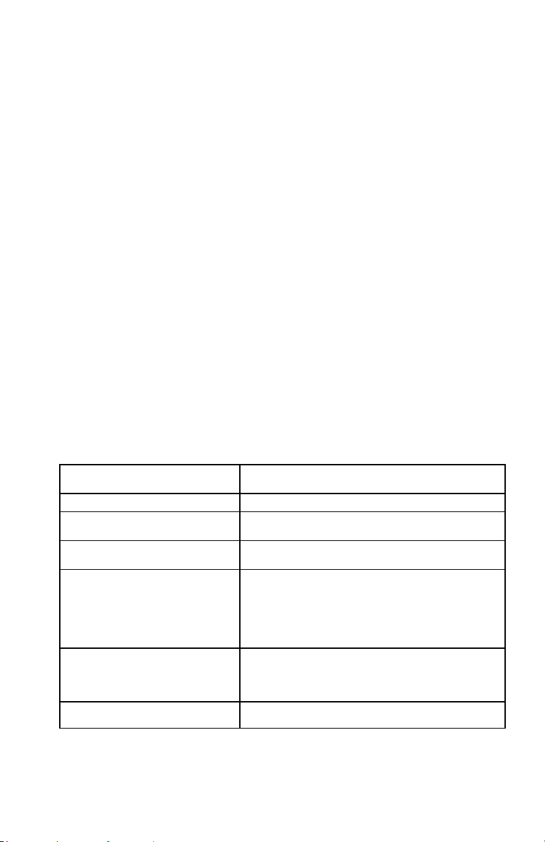
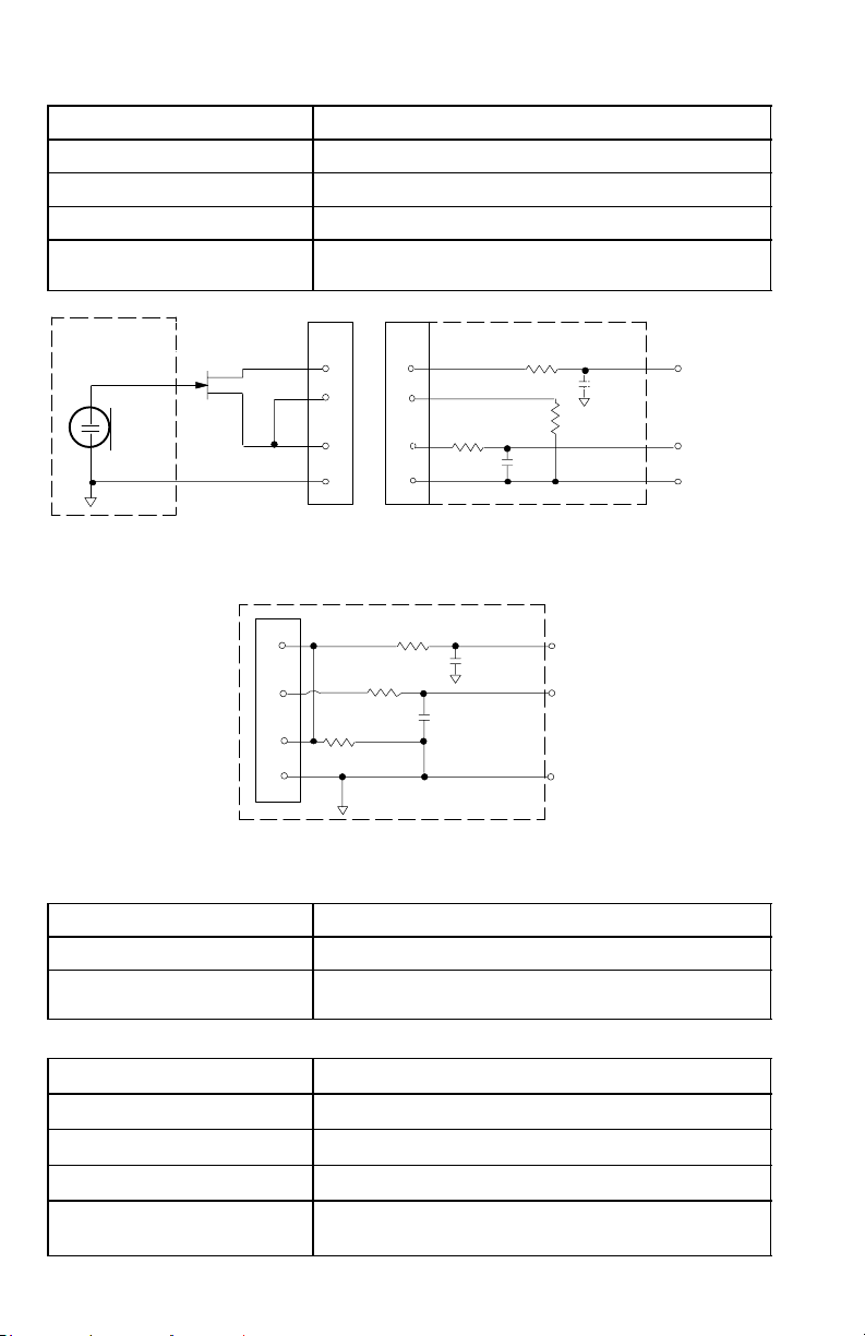
U1, U1H Transmitter Output (Figure 1)
Connector:
Actual Impedance:
Nominal Output Level:
Maximum Output Level:
Pin Assignments:
+10 dBm (+17 dBm for U1H)
+11 dBm (+18 dBm for U1H)
3
SMC
50 Ω
Shell = Ground
Center = Signal
Page 4
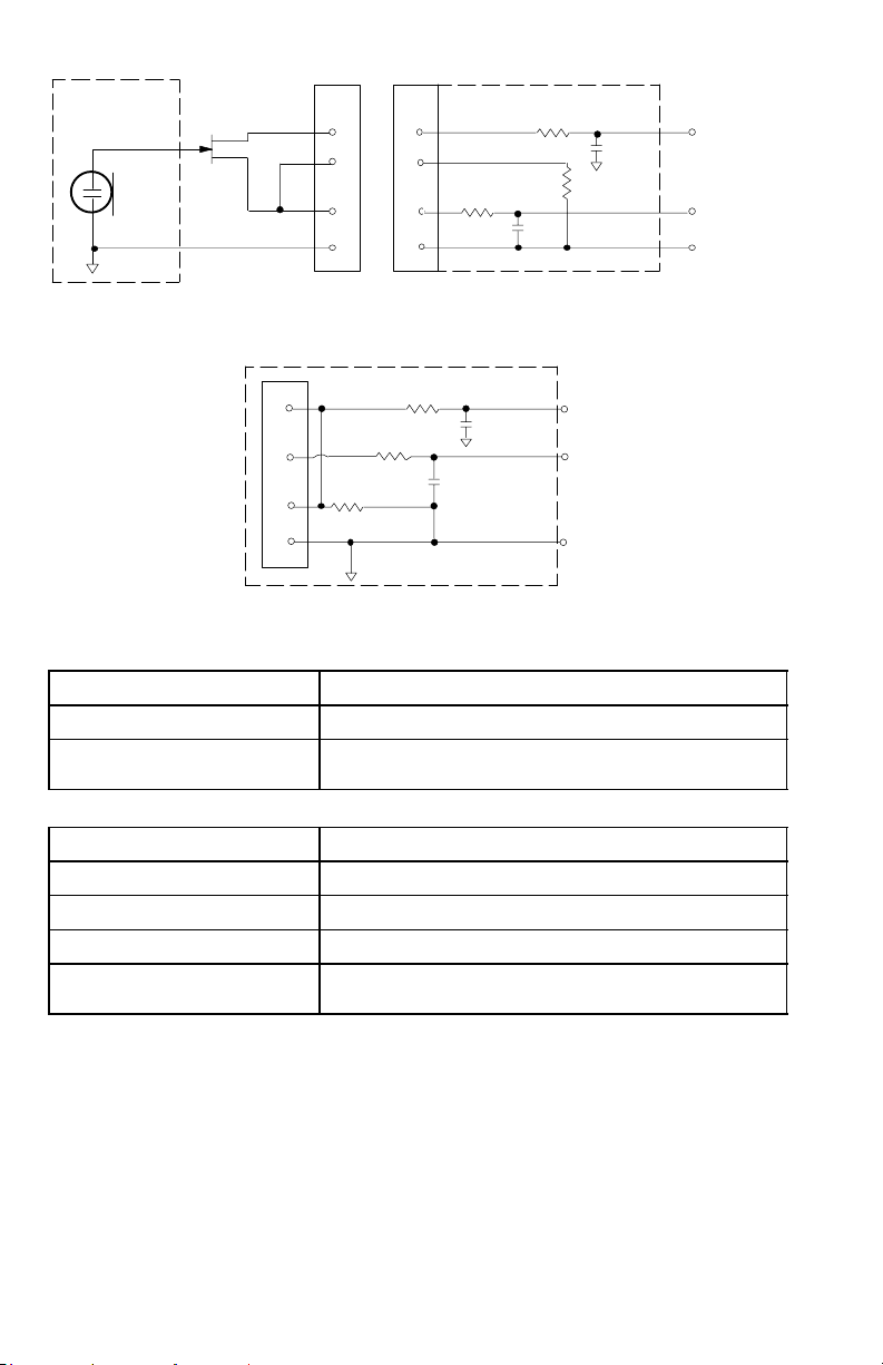
MICROPHONE
ELEMENT
NOTE: LAVALIER MIC TIES PINS 3 AND 4
TOGETHER; GUITAR CABLE DOES NOT.
U1/U1H MIC JACK BOARD
2
2
4
4
500 Ω
3
3
1
U1L (LEMO 4 PIN) MIC JACK BOARD
1
500 Ω
27 pF
20K Ω
27 pF
+5 V
AUDIO
GROUND
1
2
10K Ω
3
4
499 Ω
499 Ω
AUDIO
27 pF
BIAS
27 pF
SHIELD
FIGURE 1
U2 Transmitter Input
Input Configuration: Unbalanced, active
Actual Impedance: 20 kΩ
Maximum Input Level: 3 Vp–p (0.5 dBV) for 1% THD at minimum gain setting
using 1 kHz signal.
U2 Transmitter Output
Connector: SMC
Actual Impedance: 50 Ω
Nominal Output Level: +10 dBm
Maximum Output Level: +11 dBm
Pin Assignments: Shell = Ground
Center = Signal
4
Page 5
U4S and U4D Receiver Input
Connector: Antenna Power Input Network Interface
Connector Type: BNC IEC 25–Pin D
Actual Impedance: 50 Ω –– ––
Nominal Input
Level:
Maximum Input
Level:
–95 to –30 dBm 90–230 VAC,
50/60 Hz
+6 dBm
230 VAC, 50/60 Hz ––
(–20 dBm
CMOS Logic
recommended)
Pin Assignments: Shell = Ground
IEC Standard ––
Center = Signal
Voltage f o r
Remote Power:
12 Vdc, 150 mA
maximum
–– 5V, 700 mA max.
U4S and U4D Receiver Output
Connector: Monitor Power
Output
Configuration:
Actual
Impedance:
Nominal
Input Level:
Pin
Assignments:
Unbalanced
mono, 1/4 inch
300 Ω –– 1 kΩ 30 Ω See
–– 90 to 230
Tip = Hot
Ring = Hot
Output
–– Un-
VAC, 5A
IEC
Standard
Sleeve = Gnd
Voltage/
Current/
Phantom
Power
Protection?
*Output Level: Microphone Level = Line Level – 30 dB
Ye s –– Ye s Ye s 5V, 700 mA
High Z
Audio
Low Z
Audio*
Balanced See
balanced
Appendix in
user guide
Appendix in
user guide
–– –– CMOS
Tip = Hot
Ring/
Sleeve =
1 = Ground
2 = Hot
3 = Hot
Appendix in
user guide
Gnd
Network
Interface
resettable
polyfuse
FURNISHED ACCESSORIES
Microphone Stand Adapter (U2) WA370A. . . . . . . . . . . . . . . . . . . . . . . . . . . . . . . . . . .
Zipper Bag (U1) 26A13. . . . . . . . . . . . . . . . . . . . . . . . . . . . . . . . . . . . . . . . . . . . . . . . . . .
Zipper Bag (U2) 26A14. . . . . . . . . . . . . . . . . . . . . . . . . . . . . . . . . . . . . . . . . . . . . . . . . . .
Screwdriver 80A498. . . . . . . . . . . . . . . . . . . . . . . . . . . . . . . . . . . . . . . . . . . . . . . . . . . . .
Coaxial Antenna Cable (2 ft) UA802. . . . . . . . . . . . . . . . . . . . . . . . . . . . . . . . . . . . . . . .
1/2 Wave Antenna UA820A. . . . . . . . . . . . . . . . . . . . . . . . . . . . . . . . . . . . . . . . . . . . . . . .
Transmitter Carrying Case 65A8257. . . . . . . . . . . . . . . . . . . . . . . . . . . . . . . . . . . . . . . .
Carrying Case Insert 29B1577. . . . . . . . . . . . . . . . . . . . . . . . . . . . . . . . . . . . . . . . . . . . .
Logic
See
5
Page 6

OPTIONAL ACCESSORIES
Instrument Adapter Cable (U1) WA302. . . . . . . . . . . . . . . . . . . . . . . . . . . . . . . . . . . . . .
4–Pin Female Mini Connector, TA4F (U1) WA330. . . . . . . . . . . . . . . . . . . . . . . . . . . . .
In-Line Audio Switch (U1) WA360. . . . . . . . . . . . . . . . . . . . . . . . . . . . . . . . . . . . . . . . . . .
1.8 Meter (6 ft) Receiver-Mixer Cable (
7.6 Meter (25 ft) Antenna Extension Cable UA825. . . . . . . . . . . . . . . . . . . . . . . . . . . .
15.2 (50 ft) Meter Antenna Extension Cable UA850. . . . . . . . . . . . . . . . . . . . . . . . . . .
In–Line Active Remote Antenna Kit (800 – 830 MHz) UA830C. . . . . . . . . . . . . . . . . .
Antenna/Power Distribution System, 230 Vac UA840C. . . . . . . . . . . . . . . . . . . . . . . . .
Directional Antenna UA870. . . . . . . . . . . . . . . . . . . . . . . . . . . . . . . . . . . . . . . . . . . . . . . .
1
/4” phone to XLR) WA410. . . . . . . . . . . . . . . .
REPLACEMENT PARTS
Hardware Kit (screwdriver, mounting feet, cable clamps) 90VL1371. . . . . . . . . . . . .
Bulkhead Adapters for Front–Mounting Antennas 95A8647. . . . . . . . . . . . . . . . . . . .
230 VAC Power Cord (Schuko mains connector) 95A8247. . . . . . . . . . . . . . . . . . . . .
304 mm (12 in.) Daisy–Chain Power Cord (230 V) 95A8678. . . . . . . . . . . . . . . . . . . .
SM58 Cartridge with Grille (U2/58) R158. . . . . . . . . . . . . . . . . . . . . . . . . . . . . . . . . . .
BETA 58A Cartridge with Grille (U2/BETA 58) R179. . . . . . . . . . . . . . . . . . . . . . . . . . .
SM87 Cartridge with Grille (U2/87) R165. . . . . . . . . . . . . . . . . . . . . . . . . . . . . . . . . . . .
BETA 87A Cartridge with Grille (U2/BETA 87A) R166. . . . . . . . . . . . . . . . . . . . . . . . .
BETA 87C Cartridge with Grille (U2/BETA 87C) RPW100. . . . . . . . . . . . . . . . . . . . . .
Matte Silver Grille (U2/58) RK143G. . . . . . . . . . . . . . . . . . . . . . . . . . . . . . . . . . . . . . . . . .
Matte Silver Grille (U2/BETA 58) RK265G. . . . . . . . . . . . . . . . . . . . . . . . . . . . . . . . .
Matte Silver Grille (U2/BETA 87A) RK313G. . . . . . . . . . . . . . . . . . . . . . . . . . . . . . . .
Black Grille (U2/BETA 87C) RK214G. . . . . . . . . . . . . . . . . . . . . . . . . . . . . . . . . . . . . . . .
Black Grille (U2/BETA 58) RK323G. . . . . . . . . . . . . . . . . . . . . . . . . . . . . . . . . . . . . . . . . .
Black Grille (U2/BETA 87A) RK324G. . . . . . . . . . . . . . . . . . . . . . . . . . . . . . . . . . . . . . . .
Belt Clip (U1) 53A8247A. . . . . . . . . . . . . . . . . . . . . . . . . . . . . . . . . . . . . . . . . . . . . . . . . .
Antenna (U1) 95A8646. . . . . . . . . . . . . . . . . . . . . . . . . . . . . . . . . . . . . . . . . . . . . . . . . . .
Antenna (U2) 95A2029. . . . . . . . . . . . . . . . . . . . . . . . . . . . . . . . . . . . . . . . . . . . . . . . . . .
6
Page 7

Declaration of Conformity
We of
Shure Incorporated
222 Hartrey Ave.
Evanston IL 60202–3696 U.S.A.
847–866–2200
declare under our sole responsibility that the following products,
Model: U4S Name: UHF Diversity Receiver
Model: U4D Name: UHF Dual Channel Diversity Receiver
were tested and found to comply with Part 15 of the FCC rules.
Operation is subject to the following two conditions: (1) this device may not cause harmful interference, and (2)
this device must accept any interference received, including interference that may cause undesired operation.
Testing was completed by the following NVLAP or A2LA accredited laboratory:
D.L.S. Electronic Systems, Inc.
1250 Peterson Drive
Wheeling, Illinois 60090, U.S.A.
At the test location of
D.L.S. Electronic Systems, Inc.
166 South Carter
Genoa City, Wisconsin, 53128, U.S.A.,
Test Sites Number 1 and 2
Shure Inc., Manufacturer.
Signed:
Name, Title: Craig Kozokar, Senior Quality Engineer
Additional Information for this Shure Wireless System
This Shure wireless transmitter is accepted under FCC Part 74 and/or Part 90.
IMPORTANT: Licensing of Shure wireless microphone equipment is the user’s responsibility, and licensability depends on the user’s classification and application, and on the selected frequency. Shure
urges the user to consult the appropriate telecommunications authority before choosing and ordering frequencies.
Changes or modifications not expressly approved by Shure Inc. could void your authority to operate this equipment.
The information on this page supersedes the corresponding information in your Shure user’s guide.
Date: June 15, 1999
7
Page 8
Caractéristiques
Gamme de fréquences porteuses HF
782 à 810 MHz
Plage de fonctionnement
U1, U2 : 152,4 m minimum, dans des conditions normales ; 487,6 m dans la ligne
de visée
U1H : 275 m minimum, dans des conditions normales ; 975 m dans la ligne de
visée
REMARQUE : La plage de fonctionnement réelle dépend de l’absorption et la
réflexion des signaux HF et des parasites
Réponse en fréquence audio
50 à 15 000 Hz, ±2 dB. REMARQUE : La réponse en fréquence du système global
dépend de l’élément microphone utilisé
Plage de réglage de gain
U1, U1H : 0 à 40 dB
U2 : 0 à 26 dB
Modulation
Système à compression–extension de ±45 kHz de déviation avec
préaccentuation et désaccentuation
Puissance de sortie HF
U1, U2 : 10 mW maximum
U1H : 50 mW maximum
Gamme dynamique
>102 dB, pondéré en A
Sensibilité haute fréquence
U4S U4D
–110 dBm
12 dB SINAD
–105 dBm
30 dB SINAD
Suppression de la fréquence–image
90 dB typiques
Suppression des fréquences parasites
75 dB typiques
Atténuation limite (réf. 45 kHz de déviation)
>100 dB, pondéré en A
Polarité audio
Une pression positive sur le diaphragme du microphone (ou une tension positive
appliquée à la pointe du jack téléphone WA302) produit une tension positive à
la broche 2 par rapport à la broche 3 de la sortie basse impédance et la pointe
de la sortie haute impédance de
Distorsion système (réf. ±45 kHz de déviation, 1 kHz de modulation)
0,3 % de distorsion harmonique totale typique
Alimentation
U1, U1H, U2 : Pile alcaline AA de 1,5 V (DuracellMN1500 recommandée) ; pile au
cadmium–nickel en option
U4 : 90 à 230 V c.a., 50/60 Hz
Consommation électrique :
U4S : 9,6 W min., 13,2 W max.
U4D : 12 W min., 16 W max.
UA840 : 15 W min., 16 W max.
–107 dBm
12 dB SINAD
–102 dBm
30 dB SINAD
1
/4 po.
8
Page 9
Durée utile de la pile (typique)
U1, U2 : 12 heures (avec pile alcaline AA de 1,5 V Duracell MN1500)
U1H : 6 heures (avec pile alcaline AA de 1,5 V Duracell MN1500)
Plage de températures de fonctionnement
–20 à 50 °C REMARQUE : Les caractéristiques de la pile peuvent limiter cette
plage
Dimensions hors tout
U1 : 92,2 mm H x 64,7 mm l x 24,2 mm P
U2/58 : 254 mm L x 50,8 mm diam.
U2/BETA 58 : 254 mm L x 53,2 mm diam.
U2/87 : 228,6 mm x 49,2 mm diam.
U2/BETA 87 : 216 mm L x 50,8 mm diam.
U4S/U4D : 44,5 mm H x 482,6 mm l x 295,3 mm P
Poids net
U1, U1H : 175,2 g sans pile
U2/58, U2/BETA 58 : 375,6 g sans pile
U2/87, U2/BETA 87 : 303,1 g sans pile
U4S : 3,30 kg
U4D : 3,85 kg
Homologation
U1*, U2 : Type BAPT approuvé pour FTZ 17TR 2019 et BAPT 122 R1 ; CEM
approuvé pour ETS 300 445.
U4S, U4D : Certifié VDE selon EN 60 950. Type BAPT approuvé pour FTZ 17TR
2019 et BAPT 122 R1 ; CEM approuvé pour ETS 300 445. Conforme à la
directive de basse tension.
Les systèmes type UHF approuvés et CEM approuvés sont autorisés à porter la
marque CE.
*L’émetteur U1H n’a pas les mêmes certifications que l’émetteur U1.
Entrée de l’émetteur U1, U1H
Connecteur :
Configuration d’entrée :
Impédance réelle :
Niveau d’entrée maximum :
Connecteur Miniature femelle à 4 broches,
(TA4F) ou LEMO (en option)
Asymétrique, active
18 kΩ avec micro–cravate
1 MΩ avec câble d’instrument
6 V c. à c. (+7 dBV) pour DHT de 1 % au régla-
ge de gain minimum utilisant un signal de 1 kHz.
Broche 1 : Masse
Broche 2 : +5 V
Désignation des broches du
connecteur miniature (TA4F) :
Broche 4 : Masse via une résistance de 20kΩ.
Broche 3 : Audio
(Sur le câble d’adaptateur d’instrument, la bro-
che 4 est isolée)
Broche 1 : Broche 3 et masse via 10 kΩ
Désignation des broches du
connecteur LEMO :
Broche 2 : +5 V
Broche 3 : Broche 1
Broche 4 : Blindage (masse pour biais positif)
Tension vers l’alimentation à
distance :
+5 V fournis à la capsule du microphone
9
Page 10
Sortie de l’émetteur U1, U1H (Figure 1)
Connecteur :
Impédance réelle :
Niveau de sortie nominal :
Niveau de sortie maximum :
Désignation des broches :
+10 dBm (+17 dBm pour U1H)
+11 dBm (+18 dBm pour U1H)
SMC
50 Ω
Capot = masse
Centre = signal
ÉLÉMENT
MICROPHONE
REMARQUE : LE MICRO–CRAVATE RELIE
ENSEMBLE LES BROCHES 3 ET 4 ; LE
CÂBLE DE GUITARE NE LE FAIT PAS.
1
2
3
4
2
2
4
4
3
3
1
CARTE DU JACK DE MICRO U1L
(LEMO À 4 BROCHES)
10 kΩ
1
499 Ω
499 Ω
CARTE DU JACK
DE MICRO U1/U1H
500 Ω
AUDIO
27 pF
BIAIS
27 pF
BLINDAGE
500 Ω
27 pF
20 kΩ
27 pF
+5 V
AUDIO
MASSE
Figure 1
Entrée de l’émetteur U2
Configuration d’entrée : Asymétrique, active
Impédance réelle : 20 kΩ
Niveau d’entrée maximum : 3 V c. à c. (0,5 dBV) pour DHT de 1 % au réglage de
gain minimum utilisant un signal de 1 kHz.
Sortie de l’émetteur U2
Connecteur :
Impédance réelle :
Niveau de sortie nominal :
Niveau de sortie maximum :
Désignation des broches :
SMC
50 Ω
+10 dBm
+11 dBm
Capot = masse
Centre = signal
10
Page 11

Entrée des récepteurs U4S et U4D
Connecteur : Antenne Entrée secteur Interface réseau
Type de
BNC IEC D à 25 broches
connecteur :
Impédance réelle : 50 Ω –– ––
Niveau d’entrée
nominal :
Niveau d’entrée
maximum :
–95 à –30 dBm 90 à 230 V c.a.,
50/60 Hz
+6 dBm
(–20 dBm
230 V c.a., 50/60
Hz
Logique CMOS
recommandés)
Désignation des
broches :
Tensi on ver s
l’alimentation à
Capot = masse
Centre = signal
12 V c.c., 150 mA
maximum
Norme IEC ––
–– 5 V, 700 mA max.
distance :
Sortie des récepteurs U4S et U4D
––
Connecteur : Retour de
Configuration
de sortie :
scène
Mono
asymétrique,
Sortie de
puissance
Audio à
haute
impédance
Basse
impédance
Audio*
–– AsymétriqueSymétrique Voir
Interface
réseau
l’annexe
1/4 po
Impédance
réelle :
Niveau
d’entrée
nominal :
Désignation
des broches :
Protection de
tension–inten
sité–alimentat
ion fantôme ?
*Niveau de sortie : Niveau microphone = niveau ligne – 30 dB
300 Ω –– 1 kΩ 30 Ω Voir
–– 90 à 230 V
–– –– Logique
c.a., 5 A
Pointe = positif
Anneau =
positif
Tige = masse
Norme IEC Pointe =
positif
Anneau/tig
e = masse
1 = masse
2 = positif
3 = positif
Oui –– Oui Oui Polyfuse à
l’annexe
CMOS
l’annexe
réarmemen
t de 5 V,
700 mA
ACCESSOIRES FOURNIS
Adaptateur de pied de microphone (U2) WA370A. . . . . . . . . . . . . . . . . . . . . . . . . . . . .
Sac à glissière (U1) 26A13. . . . . . . . . . . . . . . . . . . . . . . . . . . . . . . . . . . . . . . . . . . . . . . .
Sac à glissière (U2) 26A14. . . . . . . . . . . . . . . . . . . . . . . . . . . . . . . . . . . . . . . . . . . . . . . .
Tournevis 80A498. . . . . . . . . . . . . . . . . . . . . . . . . . . . . . . . . . . . . . . . . . . . . . . . . . . . . . .
Câble coaxial d’antenne (2 pi) UA802. . . . . . . . . . . . . . . . . . . . . . . . . . . . . . . . . . . . . . .
Antenne demi–onde UA820A. . . . . . . . . . . . . . . . . . . . . . . . . . . . . . . . . . . . . . . . . . . . . .
Mallette de transport pour émetteur 65A8257. . . . . . . . . . . . . . . . . . . . . . . . . . . . . . . .
Insertion de mallette de transport 29B1577. . . . . . . . . . . . . . . . . . . . . . . . . . . . . . . . . .
Voir
11
Page 12

Accessoires en option
Câble d’adaptateur d’instrument (U1) WA302. . . . . . . . . . . . . . . . . . . . . . . . . . . . . . . . .
Connecteur Miniature (TA4F) femelle à 4 broches (U1) WA330. . . . . . . . . . . . . . . . . .
Interrupteur audio en ligne (U1) WA360. . . . . . . . . . . . . . . . . . . . . . . . . . . . . . . . . . . . . .
Câble récepteur–mélangeur de 1,8 m (6 pi) (écouteur à XLR de
Câble d’extension d’antenne de 7,6 m (25 pi) UA825. . . . . . . . . . . . . . . . . . . . . . . . . .
Câble d’extension d’antenne de 15,2 m (50 pi ) UA850. . . . . . . . . . . . . . . . . . . . . . . .
Kit d’antenne à distance active en ligne (800 à 830 MHz) UA830C. . . . . . . . . . . . . . .
Répartiteur d’antenne/alimentation, 230 V c.a. UA840C. . . . . . . . . . . . . . . . . . . . . . . .
Antenne directionnelle UA870. . . . . . . . . . . . . . . . . . . . . . . . . . . . . . . . . . . . . . . . . . . . . .
1
/4 po) WA410. . . .
Pièces de rechange
Kit de quincaillerie (tournevis, pieds de montage, serre–câble) 90VL1371. . . . . . . .
Adaptateurs traversants pour antennes à montage frontal 95A8647. . . . . . . . . . . . .
Cordon d’alimentation de 230 V c.a. (fiches secteur Schuko) 95A8247. . . . . . . . . . .
Cordon d’alimentation pour raccordement en chaîne
de 304 mm (12 po) (230 V) 95A8678. . . . . . . . . . . . . . . . . . . . . . . . . . . . . . . . . . . . . .
Capsule SM58 avec grille (U2/58) R158. . . . . . . . . . . . . . . . . . . . . . . . . . . . . . . . . . . . .
Capsule BETA 58A avec grille (U2/BETA 58) R179. . . . . . . . . . . . . . . . . . . . . . . . . . .
Capsule SM87 avec grille (U2/87) R165. . . . . . . . . . . . . . . . . . . . . . . . . . . . . . . . . . . . .
Capsule BETA 87A avec grille (U2/BETA 87A) R166. . . . . . . . . . . . . . . . . . . . . . . . . .
Capsule BETA 87C avec grille (U2/BETA 87C) RPW100. . . . . . . . . . . . . . . . . . . . . . .
Grille argent mat (U2/58) RK143G. . . . . . . . . . . . . . . . . . . . . . . . . . . . . . . . . . . . . . . . . . .
Grille argent mat (U2/BETA 58) RK265G. . . . . . . . . . . . . . . . . . . . . . . . . . . . . . . . . .
Grille argent mat (U2/BETA 87A) RK313G. . . . . . . . . . . . . . . . . . . . . . . . . . . . . . . . .
Grille noire (U2/BETA 87C) RK214G. . . . . . . . . . . . . . . . . . . . . . . . . . . . . . . . . . . . . . . .
Grille noire (U2/BETA 58) RK323G. . . . . . . . . . . . . . . . . . . . . . . . . . . . . . . . . . . . . . . . . .
Grille noire (U2/BETA 87A) RK324G. . . . . . . . . . . . . . . . . . . . . . . . . . . . . . . . . . . . . . . . .
Attache pour ceinture (U1) 53A8247A. . . . . . . . . . . . . . . . . . . . . . . . . . . . . . . . . . . . . . .
Antenne (U1) 95A8646. . . . . . . . . . . . . . . . . . . . . . . . . . . . . . . . . . . . . . . . . . . . . . . . . . .
Antenne (U2) 95A2029. . . . . . . . . . . . . . . . . . . . . . . . . . . . . . . . . . . . . . . . . . . . . . . . . . .
12
Page 13

SPEZIFIKATIONEN
Frequenzbereich
782–810 MHz
Reichweite
150 m Minimum unter Normalbedingungen; 500 m maximal. HINWEIS: Die
tatsächliche Reichweite hängt von der HF-Signalabsorption, -reflexion und
-interferenz ab.
Audiofrequenzgang
50 bis 15,000 Hz, "2 dB. HINWEIS: Der Gesamtaudiofrequenzgang des
Systems hängt vom Mikrophonelement ab.
Verstärkungsbereich
U1: 0 bis 40 dB
U2: 0 bis 26 dB
Modulation
"45 kHz Komprimierungs–/Dekomprimierungssystem mit Preemphasis und
Deemphasis.
Dynamikbereich
>102 dB, mit A–Bewertung
HF–Empfindlichkeit:
U4S U4D
–110 dBm
12 dB SINAD
–105 dBm
30 dB SINAD
–107 dBm
12 dB SINAD
–102 dBm
30 dB SINAD
HF–Leistungsabgabe
U1, U2: maximal 10 mW
Spiegelselektion
90 dB (typisch)
Oberwellenunterdrückung
75 dB (typisch)
Grenzschalldämmung (bzgl. 45 kHz Abweichung)
>100 dB, mit A–Bewertung
Audiopolarität
Positiver Druck auf die Mikrophonmembran (oder positive Spannung an der
Spitze des Klinkensteckers WA302) erzeugt positive Spannung an Pin 2
hinsichtlich Pin 3 des Niederimpedanzausgangs und der Spitze des
Hochimpedanz–6,3mm–Ausgangs.
Systemverzerrung (bzgl. "45 kHz Abweichung, 1 kHz Modulation)
0,3% Gesamtklirrfaktor (typisch)
Stromversorgung
U1, U2: 1,5–V–Alkalibatterie (Duracell MN 1500 wird empfohlen), wahlweise NiCd
U4: 90 bis 230 V Wechselstrom, 50/60 Hz
Leistungsaufnahme: 9.6 W min, 13.2 W max (U4S)
12 W min, 16 W max (U4D)
15 W min, 16 W max (UA840)
Batterielebensdauer Sender (typisch)
12 Stunden (für Duracell MN 1500 1,5–V–Alkalibatterien)
13
Page 14

Betriebstemperaturbereich
–20_ bis 50_ C HINWEIS: Batterieeigenschaften können diesen Bereich
einschränken.
Gesamtabmessungen
U1, H x B x T: 92,2 mm x 64,7 mm x 24,2 mm
U2/58, L x Durchmesser: 254 mm x 50,80 mm
U2/Beta 58A, L x Durchmesser: 254 mm x 53,2 mm
U2/87, L x Durchmesser: 228,6 mm x 49,2 mm
U2/BETA 87, L x Durchmesser: 216 mm x 50,8 mm
U4S/U4D: H x B x T: 44,5 mm x 482,6 mm x 295,3 mm
Nettogewicht
U1: 175,2 g ohne Batterien
U2/58, U2/Beeta 58A: 375,6 g ohne Batterien
U2/87, U2/BETA 87: 303,1 g ohne Batterien
U4S: 3,3 kg
U4D: 3,85 kg
Zulassung
U1, U2: Genehmigt durch BAPT unter FTZ 17TR 2019, BAPT 122 R1; EMC
geprüft unter ETS 300 445.
U4S, U4D: Zugelassen durch BAPT unter FTZ 17TR 2019 und BAPT 122 R1;
VDE Genehmigt durch EN600950; EMC geprüft unter ETS 300 445.
UHF–und EMC–zugelassene Geräte sind berechtigt das CE–Zeichen zu tragen.
U1–Sendereingang (Abbildung 1)
Anschluß: 4-Polige miniatur steckverbindung (TA4F) oder
Eingangskonfiguration: Asymmetrisch, aktiv
Tatsächliche Impedanz:
Maximaler Eingangs-
pegel:
TA4F
Pinkonfiguration:
LEMO Pinkonfiguration: Pin 1: an Pin 3 und 10 kΩ an Erdung
Spannung für
Phantomspeisung:
6 Vss (+7 dBV) für 1% Gesamtklirrfaktor bei
minimaler Verstärkungseinstellung mit 1 kHz Signal
Instrumentenadapterkabeln ist Pin 4 nicht geerdet)
LEMO–Anschluß (optional)
18 k Bei Lavalier–Mikrophon
1M mit Instrumentenkabel
Pin 1: Erdung
Pin 2: +5V
Pin 3: Audio
Pin 4 : an 20 kΩ für Erdung & Audio (bei
Pin 2: +5V
Pin 3: Pin 1
Pin 4: an der Schirmung (Erdung)
+5 V Versorgung an Mikrophonkapsel
14
Page 15

MIKROPHON
ELEMENT
HINWEIS: DAS LAVALIERKABEL VERBINDET Pin 3 UND 4; DAS
GITARRENKABEL ERFÜLLT DIESE FUNKTION NICHT
U1L (LEMO–4 POLIG) MIKROFONBUCHSE
2
4
3
1
U1 MIKROPHON–KLINKENPLATTE
2
4
500 Ω
3
1
500 Ω
27 pF
20K Ω
27 pF
+5 V
AUDIO
ERDUNG
1
2
10K Ω
3
4
499 Ω
499 Ω
27 pF
AUDIO
27 pF
VORSPANNUNG
ABSCHIRMUNG
ABBILDUNG 1
U1–Senderausgang
Anschlußtyp: SMC
Tatsächliche Impedanz:
50
Nominaler Ausgangs pegel: +10 dBm
Maximaler Ausgangs pegel: +11 dBm
Pinkonfiguration: Mantel = Erdung
Mitte = Signal
U2–Sendereingang
Eingangskonfiguration: Asymmetrisch, aktiv
Tatsächliche Impedanz:
MaximaleR Eingangspegel: 3 Vss (+0.5 dBV) für 1% Gesamtklirrfaktor bei
minimaler Verstärkungseinstellung und
20 K
1–kHz–Signal
U2–Senderausgang
Anschlußtyp: SMC
Tatsächliche Impedanz:
Nominaler Ausgangspegel: +10 dBm
Maximaler Ausgangspegel: +11 dBm
Pinkonfiguration: Mantel = Erdung
Mitte = Signal
15
50
Page 16

U4S– und U4D–Empfängereingang
Anschluß: Antenne Netzeingang Netzschnittstelle
Anschlußtyp: BNC IEC 25–polig D
Tatsächliche
Impedanz:
Nominaler
Eingangspegel:
50 Ω –– ––
–95 bis –30 dBm 90 bis 230 V
Wechselstrom
50/60 Hz
CMOS–Logik
Maximaler
Eingangspegel:
Pinkonfiguration: Mantel = Erdung
Spannung für
Remote
speisung:
+6 dBm
(–20 dBm
empfohlen)
Mitte = Signal
12 V , 150 mA
max.
U4S– und U4D–Empfängerausgang
Anschluß: Monitor–
Ausgangs–
konfiguration
:
Tatsächliche
Impedanz:
Nominaler
Eingang–
spegel:
Pinkon–
figuration:
Spannungs–/
Strom–/
Phantom–
speisungs–
schutz?
*Mikrofonpegel = Linepegel –30 dB
ausgsng
Asymmetrisch
Mono,
6,3mm–Klinke
300 Ω –– 1 kΩ 30 Ω siehe
–– 90 bis
Spitze = unter
Spannung
tension
Ring = unter
Spannung
Hülse =
Erdung
Ja Ja Ja ––
Strom-
ausgang
–– Asymme–
230 V
Wechsel
strom,
5A
IEC
Standard
230 V
Wechselstrom,
50/60 Hz
IEC–Standard ––
–– 5 V, 700 mA max.
High
Z–Audio
trisch
–– –– CMOS–
Spitze =
unter
Spannung
Ring/Hülse
= Erdung
Low
Z–Audio*
Symme-
trisch
1 = Erdung
2 = unter
Spannung
3 = unter
Spannung
Netzschnitt-
(Bedienungs
(Bedienungs
(Bedienungs
––
stelle
siehe
Anhang
anleitung)
Anhang
anleitung)
Logik
siehe
Anhang
anleitung)
16
Page 17

MITGELIEFERTES ZUBEHÖR
Mikrofonstativadapter (U2) WA370A. . . . . . . . . . . . . . . . . . . . . . . . . . . . . . . . . . . . . . . .
Tasche (U1) 26A13. . . . . . . . . . . . . . . . . . . . . . . . . . . . . . . . . . . . . . . . . . . . . . . . . . . . . .
Tasche (U2) 26A14. . . . . . . . . . . . . . . . . . . . . . . . . . . . . . . . . . . . . . . . . . . . . . . . . . . . . .
Schraubendreher 80A498. . . . . . . . . . . . . . . . . . . . . . . . . . . . . . . . . . . . . . . . . . . . . . . . .
Antennenkabel (60cm) UA802. . . . . . . . . . . . . . . . . . . . . . . . . . . . . . . . . . . . . . . . . . . . .
Halbwellenantenne (782–810 MHz) UA820A. . . . . . . . . . . . . . . . . . . . . . . . . . . . . . . . .
Sendertragetasche 65A8257. . . . . . . . . . . . . . . . . . . . . . . . . . . . . . . . . . . . . . . . . . . . . .
Sendertragetasche Einsatzstück 29B1577. . . . . . . . . . . . . . . . . . . . . . . . . . . . . . . . . . .
ZUSATZAUSRÜSTUNG
Instrumentenadapterkabel (U1) WA302. . . . . . . . . . . . . . . . . . . . . . . . . . . . . . . . . . . . . .
4–polige Buchse TA4F, (U1) WA330. . . . . . . . . . . . . . . . . . . . . . . . . . . . . . . . . . . . . . . . .
Inline–Audioschalter (U1) WA360. . . . . . . . . . . . . . . . . . . . . . . . . . . . . . . . . . . . . . . . . . .
1,8 m Empfänger–Mischpultkabel (6,3mm Klinken– an XLR–Anschluß) WA410. . .
7,6 m Antennenverlängerungskabel UA825. . . . . . . . . . . . . . . . . . . . . . . . . . . . . . . . . .
15,2 m Antennenverlängerungskabel UA850. . . . . . . . . . . . . . . . . . . . . . . . . . . . . . . . .
Inline–Antennenverstärker (800–830 MHz) UA830C. . . . . . . . . . . . . . . . . . . . . . . . . . .
Antennen–/Stromverteilungssystem, 230 V Wechselstrom UA840C. . . . . . . . . . . . . .
Aktive UHF–Richtantenne UA870. . . . . . . . . . . . . . . . . . . . . . . . . . . . . . . . . . . . . . . . . .
ERSATZTEILE
Beschlagteile (Schraubendreher, Montagefüßchen, Kabelklemmen) 90VL1371. . . . . .
Trennwandadapter für Frontantennen 95A8647. . . . . . . . . . . . . . . . . . . . . . . . . . . . . .
230 V Wechselstromkabel 95A8247. . . . . . . . . . . . . . . . . . . . . . . . . . . . . . . . . . . . . . . .
304 mm Verkettungsstromkabel (230 V) 95A8678. . . . . . . . . . . . . . . . . . . . . . . . . . . .
Microfonkapsel SM58 mit Grill (U2/58) R158. . . . . . . . . . . . . . . . . . . . . . . . . . . . . . . . .
Microfonkapsel Beta 58AA mit Grill (U2/Beta 58) R179. . . . . . . . . . . . . . . . . . . . . . . .
Microfonkapsel SM87 mit Grill (U2/87) R165. . . . . . . . . . . . . . . . . . . . . . . . . . . . . . . . .
Microfonkapsel BETA 87A mit Grill (U2/BETA 87A) R166. . . . . . . . . . . . . . . . . . . . . .
Microfonkapsel BETA 87C mit Grill (U2/BETA 87C) RPW100. . . . . . . . . . . . . . . . . . .
Grill Mattsilber (U2/58) RK143G. . . . . . . . . . . . . . . . . . . . . . . . . . . . . . . . . . . . . . . . . . . . .
Grill Mattsilber (U2/BETA 58) RK265G. . . . . . . . . . . . . . . . . . . . . . . . . . . . . . . . . . . . . . .
Grill Mattsilber (U2/BETA 58) RK313G. . . . . . . . . . . . . . . . . . . . . . . . . . . . . . . . . . . . . . .
Grill Schwarz (U2/BETA 87C) RK214G. . . . . . . . . . . . . . . . . . . . . . . . . . . . . . . . . . . . . . .
Grill Schwarz (U2/BETA58) RK323G. . . . . . . . . . . . . . . . . . . . . . . . . . . . . . . . . . . . . . . .
Grill Schwarz (U2/BETA 87A) RK324G. . . . . . . . . . . . . . . . . . . . . . . . . . . . . . . . . . . . . . .
Gürtelhalter (U1) 53A8247A. . . . . . . . . . . . . . . . . . . . . . . . . . . . . . . . . . . . . . . . . . . . . . . .
Antenne (U1) 95A8646. . . . . . . . . . . . . . . . . . . . . . . . . . . . . . . . . . . . . . . . . . . . . . . . . . .
Antenne (U2) 95A2029. . . . . . . . . . . . . . . . . . . . . . . . . . . . . . . . . . . . . . . . . . . . . . . . . . .
17
Page 18

Especificaciones
Gama de frecuencias portadoras
782–810 MHz
Alcance
U1, U2: 152,4 m mínimo, bajo condiciones típicas; 487,6 m de trayectoria visual
U1H: 275 m mínimo, bajo condiciones típicas; 975 m de trayectoria visual
NOTA: El alcance real depende de los niveles de absorción, reflexión e interferencia
de RF
Respuesta de audiofrecuencia
50 – 15.000 Hz, ±2 dB. NOTA: La respuesta de frecuencia del sistema total
depende del elemento de micrófono utilizado
Gama de ajuste de ganancia
U1, U1H: 0 – 40 dB
U2: 0 – 26 dB
Modulación
Desviación de frecuencia de ±45 kHz con sistema de compresor/expansor y filtros
de preénfasis y deénfasis
Potencia de salida RF
U1, U2: 10 mW máx.
U1H: 50 mW máx.
Rango dinámico
>102 dB (ponderación A)
Sensibilidad de RF
U4S U4D
–110 dBm
12 dB SINAD
–105 dBm
30 dB SINAD
Rechazo de imágenes
90 dB típico
Rechazo de señales espurias
75 dB típico
Silenciamiento máximo (ref. desviación de 45 kHz)
>100 dB (ponderación A)
Polaridad de señal de audio
Una presión positiva en el diafragma del micrófono (o un voltaje positivo aplicado
a la punta del enchufe tipo audífono WA302) produce un voltaje positivo en la
clavija 2 con respecto a la clavija 3 de la salida de baja impedancia y con
respecto a la punta de la salida de alta impedancia con jack de
Distorsión de sistema (ref. desviación de ±45 kHz, modulación de 1 kHz)
Distorsión armónica total: 0,3% típica
Requisitos de alimentación
U1, U1H, U2: Pilas tamaño AA de 1,5 V (se recomienda usar pilas Duracell
MN1500); pilas de NiCad opcionales.
U4: 90 – 230 VCA, 50/60 Hz
Consumo de potencia:
U4S: 9,6 W mín., 13,2 W máx.
U4D: 12 W mín.,16 W máx.
UA840: 15 W mín., 16 W máx.
–107 dBm
12 dB SINAD
–102 dBm
30 dB SINAD
1
/4 pulg.
18
Page 19

Duración de la pila (típica)
U1, U2: 12 horas (con pilas alcalinas Duracell MN1500 AA de 1,5 V)
U1H: 6 horas (con pilas alcalinas Duracell MN1500 AA de 1,5 V)
Gama de temperatura de funcionamiento
–20°C a 50°C NOTA: Las características de la pila podrían limitar esta gama.
Dimensiones totales
U1: 92,2 mm (largo) x 64,7 mm (ancho) x 24,2 mm (prof.)
U2/58: 254 mm (largo) x 50,8 mm (diám.)
U2/BETA 58: 254 mm (largo) x 53,2 mm (diám.)
U2/87: 228,6 mm (largo) x 49,2 mm (diám.)
U2/BETA 87: 216 mm (largo) x 50,8 mm (diám.)
U4S/U4D: 44,5 mm (alt.) x 482,6 mm (an.) x 295,3 mm (prof.)
Peso neto
U1, U1H: 175,2 g sin pila
U2/58, U2/BETA 58: 375,6 g sin pila
U2/87, U2/BETA 87: 303,1 g sin pila
U4S: 3,30 kg
U4D: 3,85 kg
Certificaciones
U1*, U2: BAPT aprobado por espécimen según FTZ 17TR 2019 y BAPT 122 R1;
compatibilidad electromagnética aprobada según ETS 300 445.
U4S, U4D: Homologado por VDE según EN 60 950. BAPT aprobado por
espécimen según FTZ 17TR 2019 y BAPT 122 R1; compatibilidad
electromagnética aprobada según ETS 300 445. Cumple con la directriz de
bajo voltaje.
Los sistemas UHF aprobados por espécimen y con compatibilidad electromagnética
aprobada pueden portar el distintivo ”CE”.
*El transmisor U1H no tiene las mismas aprobaciones que el transmisor U1.
Entrada de transmisor U1, U1H
Conector:
Configuración de entrada:
Impedancia real:
Conector miniatura hembra de 4-Clavijas,
TA4F o conector LEMO (opcional)
Desequilibrada, activa
18 kΩ con micrófono de corbata
1 MΩ con cable para instrumentos
6 Vp–p (+7 dBV) para 1% de THD usando se-
Nivel máximo de entrada:
ñal de 1 kHz con ganancia en valor de ajuste
mínimo.
Clavija 1: Conectada a tierra
Clavija 2: Conectada a +5 V
Designación de clavijas en
conector TA4F :
Clavija 4: Conectada por una resistencia de 20
Clavija 3: Conectada a audio
kΩ a tierra.
(En el cable adaptador para instrumento, la
clavija 4 flota)
Clavija 1: Conectada a la clavija 3 y a través
de una resistencia de 10 kΩ a tierra
Designación de clavijas de
conector LEMO:
Clavija 3: Conectada a la clavija 1
Clavija 2: +5 V
Clavija 4: Conectada al blindaje (a tierra para
polarización positiva)
Voltaje para alimentación
remota:
Suministro de +5 V a la cápsula del micrófono
19
Page 20

Salida de transmisor U1, U1H (Figura 1)
Conector:
Impedancia real:
Nivel nominal de salida:
Nivel máximo de salida:
Designación de clavijas:
+10 dBm (+17 dBm para U1H)
+11 dBm (+18 dBm para U1H)
SMC
50 Ω
Casco = Tierra
Centro = Señal
ELEMENTO DEL
MICROFONO
NOTA: EN EL MICROFONO DE CORBATA
SE CONECTAN LAS CLAVIJAS 3 Y 4 ENTRE
SI; EN EL CABLE DE GUITARRA NO.
TARJETA DE JACK DE MICROFONO U1L
(CONECTOR LEMO DE 4 CLAVIJAS)
1
2
3
4
2
4
3
1
10 kΩ
2
4
3
499 Ω
TARJETA DE JACK PARA
MICROFONOS U1/U1H
500 Ω
1
499 Ω
27 pF
27 pF
27 pF
AUDIO
POLARI
ZACION
BLINDAJE
500 Ω
20 kΩ
27 pF
+5 V
AUDIO
FIGURA 1
Entrada de transmisor U2
Configuración de entrada: Desequilibrada, activa
Impedancia real: 20 kΩ
Nivel máximo de entrada: 3 Vp–p (0,5 dBV) para 1% de THD usando señal de 1
kHz con ganancia en valor de ajuste mínimo.
TIERRA
Salida de transmisor U2
Conector:
Impedancia real:
Nivel nominal de salida:
Nivel máximo de salida:
Designación de clavijas:
SMC
50 Ω
+10 dBm
+11 dBm
Casco = Tierra
Centro = Señal
20
Page 21

Entrada de receptores U4S y U4D
Conector: Antena Entrada de
potencia
Tipo de conector: BNC IEC Tipo D, 25 clavijas
Impedancia real: 50 Ω –– ––
Nivel nominal de
entrada:
Nivel máximo de
entrada:
-95 – -30 dBm 90–230 VCA,
50/60 Hz
+6 dBm
230 VCA, 50/60 Hz ––
(se recomienda –20
dBm)
Designación de
clavijas:
Voltaje p ar a
alimentación
Casco = Tierra
Centro = Señal
12 VCC, 150 mA
máx.
Estándar IEC ––
–– 5 V, 700 mA máx.
remota:
Conexión a red
Lógica CMOS
Salida de receptores U4S y U4D
Conector: Monitor Potencia
de salida
Audio alta
impedancia
Audio baja
impedancia*
Conexión a
red
Configuración
de salida:
Monofónica
desequilibrada
–– Desequilibrada Equilibrada Vea el
1/4 pulg
Impedancia
real:
Nivel nominal
de entrada:
Designación
de clavijas:
300 Ω –– 1 kΩ 30 Ω Vea el
–– 90 – 230
–– –– Lógica
VCA, 5 A
Punta = Señal
Anillo = Señal
Manguito =
Estándar
IEC
Punta = Señal
Anillo/manguito
= Tierra
1 = Tierra
2 = Señal
3 = Señal
Tierra
¿Con
protección
contra voltaje
/ corriente /
alimentación
Phantom?
*Nivel de salida: Nivel de micrófono = nivel de línea – 30 dB
Sí –– Sí Sí Polifusible
ACCESORIOS SUMINISTRADOS
Pedestal para micrófono (U2) WA370A. . . . . . . . . . . . . . . . . . . . . . . . . . . . . . . . . . . . .
Bolsa con cremallera (U1) 26A13. . . . . . . . . . . . . . . . . . . . . . . . . . . . . . . . . . . . . . . . . .
Bolsa con cremallera (U2) 26A14. . . . . . . . . . . . . . . . . . . . . . . . . . . . . . . . . . . . . . . . . .
Destornillador 80A498. . . . . . . . . . . . . . . . . . . . . . . . . . . . . . . . . . . . . . . . . . . . . . . . . . .
Cable coaxial para antena (0,6 m / 2 pies) UA802. . . . . . . . . . . . . . . . . . . . . . . . . . . . .
Antena de 1/2 onda UA820A. . . . . . . . . . . . . . . . . . . . . . . . . . . . . . . . . . . . . . . . . . . . . . .
Caja de transporte del transmisor 65A8257. . . . . . . . . . . . . . . . . . . . . . . . . . . . . . . . . .
Inserto para caja de transporte 29B1577. . . . . . . . . . . . . . . . . . . . . . . . . . . . . . . . . . . .
Apéndice
(Guía del
Usuario)
Apéndice
(Guía del
Usuario)
CMOS
Vea el
Apéndice
(Guía del
Usuario)
reposicionable
de
5 V, 700 mA
21
Page 22

Accesorios opcionales
Cable adaptador para instrumento (U1) WA302. . . . . . . . . . . . . . . . . . . . . . . . . . . . . . .
Conector miniatura de 4 clavijas hembra, TA4F (U1) WA330. . . . . . . . . . . . . . . . . . . .
Interruptor de audio en línea (U1) WA360. . . . . . . . . . . . . . . . . . . . . . . . . . . . . . . . . . . .
Cable de 1,8 m (6 pies) de receptor a consola (enchufe de
Cable de extensión de antena de 7,6 m (25 pies) UA825. . . . . . . . . . . . . . . . . . . . . . .
Cable de extensión de 15,2 m (50 pies) para antena UA850. . . . . . . . . . . . . . . . . . . .
Juego activo para antenas remotas en línea (800 – 830 MHz) UA830C. . . . . . . . . . .
Sistema de distribución de antenas/alimentación, 230 VCA UA840C. . . . . . . . . . . . .
Antena direccional UA870. . . . . . . . . . . . . . . . . . . . . . . . . . . . . . . . . . . . . . . . . . . . . . . . .
1
/4 pulg a XLR) WA410.
Repuestos
Juego de tornillería (destornillador, patas de montaje, abrazaderas) 90VL1371. . . .
Adaptadores de tabique para montaje delantero de antenas 95A8647. . . . . . . . . . .
Cordón de alimentación para 230 VCA (conector tipo Schuko) 95A8247. . . . . . . . .
Cordón de alimentación para conexión
en cadena de 304 mm (12 pulg) (230 V) 95A8678. . . . . . . . . . . . . . . . . . . . . . . . . . .
Cartucho SM58 con rejilla (U2/58) R158. . . . . . . . . . . . . . . . . . . . . . . . . . . . . . . . . . . . .
Cápsula BETA 58A con rejilla (U2/BETA 58A) R179. . . . . . . . . . . . . . . . . . . . . . . . . . .
Cápsula SM87 con rejilla (U2/87) R165. . . . . . . . . . . . . . . . . . . . . . . . . . . . . . . . . . . . .
Cápsula BETA 87A con rejilla (U2/BETA 87A) R166. . . . . . . . . . . . . . . . . . . . . . . . . . .
Cápsula BETA 87C con rejilla (U2/BETA 87C) RPW100. . . . . . . . . . . . . . . . . . . . . . .
Rejilla plateada mate (U2/58) RK143G. . . . . . . . . . . . . . . . . . . . . . . . . . . . . . . . . . . . . . .
Rejilla plateada mate (U2/BETA 58) RK265G. . . . . . . . . . . . . . . . . . . . . . . . . . . . . .
Rejilla plateada mate (U2/BETA 87A) RK313G. . . . . . . . . . . . . . . . . . . . . . . . . . . . .
Rejilla negra (U2/BETA 87C) RK214G. . . . . . . . . . . . . . . . . . . . . . . . . . . . . . . . . . . . . . .
Rejilla negra (U2/BETA 58) RK323G. . . . . . . . . . . . . . . . . . . . . . . . . . . . . . . . . . . . . . . . .
Rejilla negra (U2/BETA 87A) RK324G. . . . . . . . . . . . . . . . . . . . . . . . . . . . . . . . . . . . . . .
Gancho para cinturón (U1) 53A8247A. . . . . . . . . . . . . . . . . . . . . . . . . . . . . . . . . . . . . . .
Antena (U1) 95A8646. . . . . . . . . . . . . . . . . . . . . . . . . . . . . . . . . . . . . . . . . . . . . . . . . . . .
Antena (U2) 95A2029. . . . . . . . . . . . . . . . . . . . . . . . . . . . . . . . . . . . . . . . . . . . . . . . . . . .
22
Page 23

DATI TECNICI
Gamma della frequenza di portante RF
782–810 MHz
Portata di esercizio
Minimo 152,4 m (500 piedi), in condizioni tipiche; 487.6 m, massimo.
NOTA: la portata effettiva di esercizio dipende dall’assorbimento, dalla riflessione e
dall’interferenza del segnale RF.
Risposta in audiofrequenza
Da 50 a 15.000 Hz, "2 dB. NOTA: la risposta in frequenza complessiva dipende
dall’elemento microfonico.
Campo di regolazione del guadagno
U1: da 0 a 40 dB.
U2: da 0 a 26 dB.
Modulazione
Deviazione di "45kHz (40 kHz negli RU), sistema compressore–espansore con
preenfasi e deenfasi.
Uscita di potenza RF
U1, U2: 10 mW massimo.
Gamma dinamica
>102 dB, ponderata A.
Reiezione della frequenza immagine
90 dB (valore tipico).
Reiezione dei segnali spuri
75 dB (valore tipico).
Sensibilità RF
U4S U4D
–110 dBm
12 dB SINAD
–105 dBm
30 dB SINAD
–107 dBm
12 dB SINAD
–102 dBm
30 dB SINAD
Silenziamento massimo (rif. deviazione di 45 kHz)
>100 dB, ponderato A.
Polarità audio
Una pressione positiva sul diaframma del microfono (o una tensione positiva
applicata all’estremità della spina telefonica WA302) produce una tensione
positiva sul piedino 2 rispetto al piedino 3 dell’uscita a bassa impedenza e alla
punta dell’uscita da 1/4” ad alta impedenza.
Distorsione del sistema (rif. deviazione di "45 kHz, modulazione di 1 kHz)
Distorsione armonica totale (TDH): 0,3% (valore tipico).
Alimentazione
U1, U2: pile alcaline AA da 1,5 V (si consigliano le Duracell MN1500); pile NiCd
opzionali.
U4: da 90 a 230 V c.a., 50/60 Hz.
Consunzione di potenza: 9.6 W min; 13.2 W max (U4S)
12 W min; 16 W max (U4D)
15 W min; 16 W max (UA840)
Durata della batteria (valore tipico)
12 ore (con le pile alcaline Duracell MN1500 AA da 1,5 V).
23
Page 24

Campo della temperatura di esercizio
Da –20 a 50 _C NOTA: le caratteristiche della batteria possono limitare questo
campo.
Dimensioni complessive
U1: 92,2 x 64,7 x 24,2 mm (A x L x P)
U2/58: 254 x 50,8 mm (A x diam.)
U2/BETA 58A: 254 x 53,2 mm (A x diam.)
U2/87: 228,6 x 49,2 mm (A x diam.)
U2/BETA 87: 216 x 50,8 mm (A x diam.)
U4S/U4D: 44,5 x 482,6 x 295,3 mm (A x L x P)
Peso netto
U1: 175,2 g senza batteria
U2/58, U2/BETA 58A: 375,6 g senza batteria
U2/87, U2/BETA 87: 303,1 g senza batteria
U4S: 3,30 kg; U4D: 3,85 kg
Omologazioni
U1, U2: Modello approvato a norme della BAPT FTZ 17TR 2019 i BAPT 122 R1;
conforme alla norma della Comunità Europea ETS 300 445 per compatibilità
elettromagnetica.
U4S, U4D: Conforme alla norma della Comunità Europea ETS 300 445 per
compatibilità elettromagnetica. Conforme alla directiva voltaggio basso.
I sistemi con tipo UHF approvato e con EMC approvato sono eleggibili per esebire
il marchio CE.
Ingresso del trasmettitore U1, U1H (Figura 1)
Connettore: Connettore miniatura a 4 piedini femmina (TA4F)
Configurazione d’ingresso: Sbilanciata, attiva
o LEMO (opzionali)
Impedenza effettiva:
Livello d’ingresso
massimo:
Signali ai piedini del
connettore (TA4F)
Signali ai piedini del
connettore LEMO:
Tensione alimentazione
remota
(fantasma):
18 k con microfono lavalier (cravatte)
1 M con cavo
6 Vp–p (+7 dBV) per 1% per una THD al valore
minimo di guadagno con un segnale a 1 kHz.
Piedino 1: Massa
Piedino 2: +5 V
Piedino 3: segnale Audio
Piedino 4: Collegato al resistore da 20 k a la
massa audio
(Sul
Cavo di adattamento per strumento, il piedino
4 flottare)
Piedino 1: al piedino 3 con 10 k a massa
Piedino 2: +5 V
Piedino 3: Audio
Piedino 4: Con schermo (massa)
Fornito di +5 V alla cartuccia del microfono
per strumento
24
Page 25

ELEMENTO
MICROFONICO
2
4
3
1
NOTA: PER MICROFONI LAVALIER, I PIEDINI 3 E 4 SARANNO
COLLEGATI; NON LO SARANNO PER UN CAVO PER CHITARRA.
SCHEDA JACK MIC U1L (CONNETTORE LEMO A 4 PIEDINI)
SCHEDA JACK MIC U1
2
4
500 Ω
3
1
500 Ω
27 pF
20K Ω
27 pF
+5 V
AUDIO
MASSA
499 Ω
499 Ω
27 pF
POLARIZZAZIONE
27 pF
1
2
10K Ω
3
4
AUDIO
SCHERMATURA
FIGURA 1
Uscita del trasmettitore U1
Connettore: SMC
Impedenza effettiva: 50 Ω
Livello di uscita massimo: +11 dBm
Piedinatura: Guscio = Massa
Conduttore centrale = Segnale
Ingresso del trasmettitore U2
Configurazione d’ingresso Sbilanciata, attiva
Impedenza effettiva: 20 kΩ
Livello di uscita massimo: 3 Vp–p (+0.5 dBV) per una TDH dell’1% al valore
minimo di guadagno con un segnale a 1 kHz.
Uscita del trasmettitore U2
Connettore: SMC
Impedenza effettiva: 50 Ω
Livello di uscita nominale: +10 dBm
Livello di uscita massimo: +11 dBm
Piedinatura: Guscio = Massa
Conduttore centrale = Segnale
25
Page 26

Ingressi dei ricevitori U4S e U4D
Connettore: SMC Alimentazione
Tipo di
connettore:
Impedenza
effettiva:
Livello d’ingresso
nominale:
BNC IEC “D” a 25 piedini
50 Ω –– ––
Da –95 a –30 dBm 90–230 V c.a.,
d’ingresso
50/60 Hz
Interfaccia di rete
Logica CMOS
Livello d’ingresso
massimo:
Piedinatura: Guscio = Massa
Tensione
alimentazione
remota:
+6 dBm (consigliati
–20 dBm)
Conduttore centrale
= Segnale
12 V c.c., 150 mA
max.
230 V c.a.,
50/60 Hz
A norma IEC ––
Uscite dei ricevitori U4S e U4D
Connettore: Monitoraggio Alimentazi
Configurazion
e di uscita
Impedenza
effettiva:
Livello
d’ingresso
nominale:
Piedinatura: Punta =
Protezione di
tensione/
corrente/
alimentazion
e virtuale?
*Livello di uscita: livello microfonico = livello di linea – 30 dB
Monofonica
sbilanciata,
1/4”
300 Ω –– 1 kΩ 30 Ω Vedi
–– Da 90 a
Tensione
Anello =j
Tension
Manicotto =
Massa
Si –– Si Si 5 V, 700 mA
one di
uscita
–– Sbilanciata Bilanciata Vedi
230 V c.a.,
5 A
A norma
IEC
Z audio
alta
–– –– Logica
Punta =
Tensione
Anello/
manicotto
= Massa
––
–– ––
Z audio
bass*
1 = Massa
2 =
Tensione
3 =Tensione
Interfaccia
Appendice
(Guida dell
Appendice
(Guida dell
Appendice
(Guida dell
di rete
’Utente)
’Utente)
CMOS
Vedi
’Utente)
max.
26
Page 27

ACCESSORI IN DOTAZIONE
Adattatore per supporto di microfono (U2) WA370A. . . . . . . . . . . . . . . . . . . . . . . . . . .
Busta con cerniera lampo (U1) 26A13. . . . . . . . . . . . . . . . . . . . . . . . . . . . . . . . . . . . . .
Busta con cerniera lampo (U2) 26A14. . . . . . . . . . . . . . . . . . . . . . . . . . . . . . . . . . . . . .
Cacciavite 80A498. . . . . . . . . . . . . . . . . . . . . . . . . . . . . . . . . . . . . . . . . . . . . . . . . . . . . . .
Cavo coassiale per antenna (60 cm) UA802. . . . . . . . . . . . . . . . . . . . . . . . . . . . . . . . .
Antenna a 1/2 onda (782–810 MHz) UA820A. . . . . . . . . . . . . . . . . . . . . . . . . . . . . . . . .
Custodia da trasporto per trasmettitore 65A8257. . . . . . . . . . . . . . . . . . . . . . . . . . . . . .
Inserto di custodia da trasporto per trasmettitore 29B1577. . . . . . . . . . . . . . . . . . . . .
ACCESSORI OPZIONALI
Cavo di adattamento per strumento (U1) WA302. . . . . . . . . . . . . . . . . . . . . . . . . . . . . .
Connettore femmina a 4 piedini, TA4F (U1) WA330. . . . . . . . . . . . . . . . . . . . . . . . . . . .
Interruttore audio in linea (U1) WA360. . . . . . . . . . . . . . . . . . . . . . . . . . . . . . . . . . . . . . .
Cavo ricevitore–mixer di 1,8 metri (jack telefonico da 1/4” – XLR) WA410. . . . . . . . .
Cavo di prolunga per antenna lungo 7,6 metri UA825. . . . . . . . . . . . . . . . . . . . . . . . . .
Cavo di prolunga per antenna lungo 15,2 metri UA850. . . . . . . . . . . . . . . . . . . . . . . . .
Kit per antenna remota attiva in linea (800 – 830 MHz) UA830C. . . . . . . . . . . . . . . . .
Sistema di distribuzione di alimentazione/ad antenne, 230 V c.a. UA840C. . . . . . . . . . .
Antenna UHFdirettiva, attiva UA870. . . . . . . . . . . . . . . . . . . . . . . . . . . . . . . . . . . . . . . . .
PARTI DI RICAMBIO
Kit di componenti di collegamento (cacciavite, piedini,
fascette fermacavo) 90VL1371. . . . . . . . . . . . . . . . . . . . . . . . . . . . . . . . . . . . . . . . . . . . .
Connettori da pannello per antenne a montaggio frontale 95A8647. . . . . . . . . . . . . .
Cavo di alimentazione da 230 V c.a. 95A8247. . . . . . . . . . . . . . . . . . . . . . . . . . . . . . . .
Cavo di alimentazione per collegamento in serie di 304 mm (230 V c.a.) 95A8678. . . .
Cartuccia SM58 con griglia (U2/58) R158. . . . . . . . . . . . . . . . . . . . . . . . . . . . . . . . . . . .
Cartuccia BETA 58A con griglia (U2/BETA 58) R179. . . . . . . . . . . . . . . . . . . . . . . . . .
Cartuccia SM87 con griglia (U2/87) R179. . . . . . . . . . . . . . . . . . . . . . . . . . . . . . . . . . . .
Cartuccia BETA 87A con griglia (U2/BETA 87A) R166. . . . . . . . . . . . . . . . . . . . . . . . .
Cartuccia BETA 87C con griglia (U2/BETA 87C) RPW100. . . . . . . . . . . . . . . . . . . . . .
Griglia color argento opaco (U2/58) RK143G. . . . . . . . . . . . . . . . . . . . . . . . . . . . . . . . .
Griglia color argento opaco (U2/BETA 58) RK265G. . . . . . . . . . . . . . . . . . . . . . . . . . . .
Griglia color argento opaco (U2/BETA 87A) RK313G. . . . . . . . . . . . . . . . . . . . . . . . . . .
Griglia nera (U2/87C) RK214G. . . . . . . . . . . . . . . . . . . . . . . . . . . . . . . . . . . . . . . . . . . . .
Griglia nera (U2/BETA 58) RK323G. . . . . . . . . . . . . . . . . . . . . . . . . . . . . . . . . . . . . . . . .
Griglia nera (U2/BETA 87A) RK324G. . . . . . . . . . . . . . . . . . . . . . . . . . . . . . . . . . . . . . . .
Fermaglio (U1) 53A8247A. . . . . . . . . . . . . . . . . . . . . . . . . . . . . . . . . . . . . . . . . . . . . . . . .
Antenna (U1) 95A8646. . . . . . . . . . . . . . . . . . . . . . . . . . . . . . . . . . . . . . . . . . . . . . . . . . .
Antenna (U2) 95A2029. . . . . . . . . . . . . . . . . . . . . . . . . . . . . . . . . . . . . . . . . . . . . . . . . . .
27
Page 28

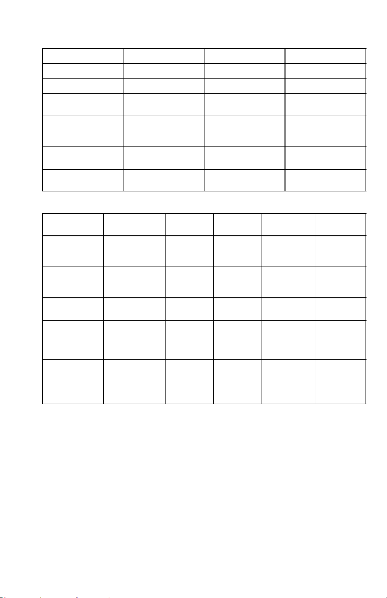
UHF WIRELESS SYSTEM COMPATIBILITY GUIDE
The following table provides a convenient overview of frequency-compatible systems
in the 782 to 810 MHz band.
Each of the primary groups (Groups 1–3) contains multiple channels which are compatible with one another. Up to 21 Shure UHF Wireless Systems can be operated simultaneously within the 782 to 810 MHz band in a single installation. If there are UHF television stations
present within the band, the number of compatible channels for any application will decrease.
NOTE: Shure recommends that you maintain a 500 kHz separation between each
receiver channel in the U4D dual channel receivers. Please contact the Shure Customer
Service Department (1–800–434–3350) if you need additional information or assistance in
frequency selection and setup.
GUIDE DE COMPATIBILITÉ DU SYSTÈME UHF SANS FIL
Le tableau suivant donne une liste générale des systèmes compatibles en fréquence
dans la bande de 782 à 810 MHz.
Chacun des groupes primaires (1 à 3) comprend plusieurs canaux compatibles les uns
avec les autres. Jusqu’à 21 systèmes Shure UHF sans fil peuvent être utilisés simultanément dans la bande de 782 à 810 MHz, dans une même installation. Lorsque des émissions
de télévision UHF utilisent la bande, le nombre de canaux compatibles est réduit, quelle que
soit l’application.
REMARQUE : Shure recommande de maintenir une séparation de 500 kHz entre chaque
canal de récepteur dans les récepteurs à canal double U4D. Ne pas hésiter à contacter le
service clientèle de Shure en Europe, composer : 49-7131-72140 Télécopie :
49-7131-721414) pour toute assistance ou informations complémentaires concernant la
sélection et le réglage des fréquences.
DRAHTLOSES UHF–SYSTEM – KOMPATIBILITÄTSHINWEISE
Die folgende Tabelle enthält eine praktische Zusammenfassung von frequenzkompatiblen Systemen im 782 bis 810 MHz Frequenzbereich.
Jede der Hauptgruppen (Gruppen 1 bis 3) enthält mehrere Kanäle, die alle miteinander
kompatibel sind. Im Frequenzbereich von 782 bis 810 MHz können in einer einzigen Installation bis zu 21 drahtlose Shure UHF–Systeme gleichzeitig verwendet werden. Falls innerhalb
des Frequenzbereichs UHF–Fernsehkanäle vorhanden sind, verringert sich die Anzahl der
für eine Anwendung zur Verfügung stehenden kompatiblen Kanäle.
HINWEIS: Shure empfiehlt, 500 kHz Kanaltrennung zwischen jedem Empfängerkanal in
den 2–Kanal–Empfängern U4D aufrecht zu erhalten. Wenn weitere Informationen oder
Unterstützung bei der Frequenzauswahl und Einrichtung gewünscht werden, wenden Sie
sich bitte an die Kundendienstabteilung von Shure In Europa, Telefon: 49-7131-72140
Fax: 49-7131-721414.
GUIA DE COMPATIBILIDAD DE SISTEMAS INALAMBRICOS DE
UHF
La tabla siguiente ofrece un resumen de los sistemas con frecuencias compatibles en
la banda de 782 a 810 MHz.
Cada uno de los grupos principales (Grupos 1–3) contiene varios canales, los cuales
son compatibles entre sí. Se pueden usar simultáneamente hasta 21 sistemas inalámbricos
UHF de Shure en la banda de 782–810 MHz en una misma instalación. Si hay emisoras de
televisión de UHF presentes en la banda, la cantidad de canales compatibles se verá reducida.
NOTA: Shure recomienda mantener una separación de 500 kHz entre los canales de cada
receptor en los receptores U4D de dos canales. Comuníquese con el Departamento de
Servicio de Shure en Europa, teléfono: 49-7131-72140 Fax: 49-7131-721414 si necesita
información adicional o ayuda para la selección de frecuencias y configuración del
sistema.
28
Page 29

GUIDA ALLA COMPATIBILITÀ DEL SISTEMA SENZA FILI UHF
La tabella che segue fornisce una conveniente descrizione generale dei sistemi compa-
tibili in frequenza nella banda da 782 a 810 MHz.
Ogni gruppo primario (gruppi 1–3) contiene più canali, tutti compatibili l’uno con l’altro.
Nella banda 782–810 MHz, in un singolo impianto si possono utilizzare simultaneamente fino
a 21 sistemi senza fili UHF Shure. Se nella banda sono presenti frequenze di stazioni televisive UHF, il numero di canali compatibili per ciascuna applicazione diminuisce.
NOTA: la Shure suggerisce di mantenere una separazione di 500 kHz tra i canali dei
ricevitori a doppio canale U4D. Chiamate il servizio di assistenza clienti Shure Numero
telefonico in Europa: 49-7131-72140 N. di fax: 49-7131-721414 per richiedere ulteriori
informazioni o assistenza nella selezione della frequenza e nella configurazione.
CHANNELS
CANAUX
KANÄLE
CANALES
CANALI
1
2
3
4
5
6
7
8
9
10
11
12
13
14
15
16
17
18
19
20
21
GROUP GROUPE GRUPPE
GRUPOS GRUPPO
1 2 3
782.250 782.500 783.250
782.875 783.625 784.750
784.625 784.125 785.500
785.250 785.125 787.500
787.250 786.375 788.375
788.750 788.375 789.000
790.750 788.875 791.500
791.250 790.750 792.250
792.500 792.375 792.750
794.875 793.375 793.750
795.500 794.625 794.375
796.625 798.125 796.750
800.000 799.375 797.750
801.750 799.875 801.500
803.000 801.375 803.000
804.000 802.000 803.500
804.750 803.625 804.750
807.125 804.875 806.750
808.375 807.000 807.500
809.000 808.750 809.000
809.875 809.625 809.625
29
Page 30

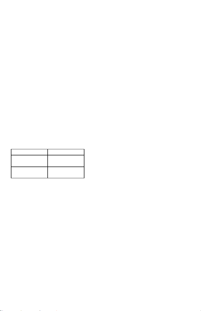
MASTER LIST
The Shure “Master List” (Groups A1–A3) is a comprehensive index of all
system frequencies offered in the 782–810 MHz band, in 125 kHz increments.
LISTE MAÎTRESSE
La “Liste maîtresse” (groupes A1 à A3) est un index complet de toutes les
fréquences de systèmes utilisées dans la bande de 782 à 810 MHz, par tranches
de 125 kHz.
HAUPTLISTE
Die Shure „Hauptliste“ (Gruppen A1–A3) enthält alle Systemfrequenzen, die im
Frequenzbereich von 782 bis 810 MHz zur Verfügung stehen (in Stufen von 125
kHz).
LISTA MAESTRA
La “Lista maestra” de Shure (Grupos A1–A3) es un índice completo de todas
las frecuencias ofrecidas en la banda de 782–810 MHz, en intervalos de 125 kHz
cada uno.
L’ELENCO PRINCIPALE
L’elenco principale Shure (gruppi A1–A3) costituisce un indice completo di
tutte le frequenze di sistema offerte nella banda 782–810 MHz, in incrementi di 125
kHz.
FREQUENCY GROUP FREQUENCY GROUP FREQUENCY GROUP
782.250 A1/2
782.375 A1/3
782.500 A1/4
782.625 A1/5
782.750 A1/6
782.875 A1/7
783.000 A1/8
783.125 A1/9
783.250 A1/10
783.375 A1/11
783.500 A1/12
783.625 A1/13
783.750 A1/14
783.875 A1/15
784.000 A1/16
784.125 A1/17
784.250 A1/18
784.375 A1/19
784.500 A1/20
784.625 A1/21
784.750 A1/22
784.875 A1/23
785.000 A1/24
785.125 A1/25
785.250 A1/26
785.375 A1/27
785.500 A1/28
785.625 A1/29
785.750 A1/30
785.875 A1/31
786.000 A1/32
786.125 A1/33
786.250 A1/34
786.375 A1/35
786.500 A1/36
786.625 A1/37
786.750 A1/38
786.875 A1/39
787.000 A1/40
787.125 A1/41
787.250 A1/42
787.375 A1/43
787.500 A1/44
787.625 A1/45
787.750 A1/46
787.875 A1/47
788.000 A1/48
788.125 A1/49
788.250 A1/50
788.375 A1/51
788.500 A1/52
788.625 A1/53
788.750 A1/54
788.875 A1/55
789.000 A1/56
789.125 A1/57
789.250 A1/58
789.375 A1/59
789.500 A1/60
789.625 A1/61
789.750 A1/62
789.875 A1/63
790.000 A1/64
790.125 A1/65
790.250 A1/66
790.375 A1/67
790.500 A1/68
790.625 A1/69
790.750 A1/70
790.875 A1/71
791.000 A1/72
791.125 A1/73
791.250 A1/74
791.375 A1/75
791.500 A1/76
791.625 A1/77
791.750 A1/78
791.875 A1/79
792.000 A1/80
792.125 A1/81
792.250 A1/82
30
Page 31

FREQUENCY GROUP FREQUENCY GROUP FREQUENCY GROUP
792.375 A1/83
792.500 A1/84
792.625 A1/85
792.750 A1/86
792.875 A1/87
793.000 A1/88
793.125 A1/89
793.250 A1/90
793.375 A1/91
793.500 A1/92
793.625 A1/93
793.750 A1/94
793.875 A1/95
794.000 A1/96
794.125 A1/97
794.250 A1/98
794.375 A1/99
794.500 A2/1
794.625 A2/2
794.750 A2/3
794.875 A2/4
795.000 A2/5
795.125 A2/6
795.250 A2/7
795.375 A2/8
795.500 A2/9
795.625 A2/10
795.750 A2/11
795.875 A2/12
796.000 A2/13
796.125 A2/14
796.250 A2/15
796.375 A2/16
796.500 A2/17
796.625 A2/18
796.750 A2/19
796.875 A2/20
797.000 A2/21
797.125 A2/22
797.250 A2/23
797.375 A2/24
797.500 A2/25
797.625 A2/26
797.750 A2/27
797.875 A2/28
798.000 A2/29
798.125 A2/30
798.250 A2/31
798.375 A2/32
798.500 A2/33
798.625 A2/34
798.750 A2/35
798.875 A2/36
799.000 A2/37
799.125 A2/38
799.250 A2/39
799.375 A2/40
799.500 A2/41
799.625 A2/42
799.750 A2/43
799.875 A2/44
800.000 A2/45
800.125 A2/46
800.250 A2/47
800.375 A2/48
800.500 A2/49
800.625 A2/50
800.750 A2/51
800.875 A2/52
801.000 A2/53
801.125 A2/54
801.250 A2/55
801.375 A2/56
801.500 A2/57
801.625 A2/58
801.750 A2/59
801.875 A2/60
802.000 A2/61
802.125 A2/62
802.250 A2/63
802.375 A2/64
802.500 A2/65
802.625 A2/66
802.750 A2/67
802.875 A2/68
803.000 A2/69
803.125 A2/70
803.250 A2/71
803.375 A2/72
803.500 A2/73
803.625 A2/74
803.750 A2/75
803.875 A2/76
804.000 A2/77
804.125 A2/78
804.250 A2/79
804.375 A2/80
804.500 A2/81
804.625 A2/82
804.750 A2/83
804.875 A2/84
805.000 A2/85
805.125 A2/86
805.250 A2/87
805.375 A2/88
805.500 A2/89
805.625 A2/90
805.750 A2/91
805.875 A2/92
806.000 A2/93
806.125 A2/94
806.250 A2/95
806.375 A2/96
806.500 A2/97
806.625 A2/98
806.750 A2/99
806.875 A3/1
807.000 A3/2
807.125 A3/3
807.250 A3/4
807.375 A3/5
807.500 A3/6
807.625 A3/7
807.750 A3/8
807.875 A3/9
808.000 A3/10
808.125 A3/11
808.250 A3/12
808.375 A3/13
808.500 A3/14
808.625 A3/15
808.750 A3/16
808.875 A3/17
809.000 A3/18
809.125 A3/19
809.250 A3/20
809.375 A3/21
809.500 A3/22
809.625 A3/23
809.750 A3/24
809.875 A3/25
31
Page 32

SHURE Incorporated Web Address: http://www.shure.com
5800 W. Touhy Avenue, Niles, IL 60714-4608, U.S.A.
Phone: 800-257-4873 Fax: 847-866-2279
In Europe, Phone: 49-7131-72140 Fax: 49-7131-721414
In Asia, Phone: 852-2893-4290 Fax: 852-2893-4055
Elsewhere, Phone: 847-866-2200 Fax: 847-866-2585
32
 Loading...