

Page 1

Цифровой автоматический
Mixer automatico IntelliMix®
IntelliMix
Mixer Automático Digital
SCM820デジタルIntelliMix®オ ート
SCM820 Digitaler automatischer
микшер SCM820 Digital IntelliMix
Mezcladora automática digital
IntelliMix® numérique SCM820
SCM820 Digital IntelliMix
Mélangeur automatique
SCM820 Digital IntelliMix
IntelliMix
®
Digital SCM820
SCM820 디지털
Mixer Otomatis
digitale SCM820
SCM820 IntelliMix
Mischer IntelliMix
Automatic Mixer
IntelliMix
®
자동 믹서
自动混音器
ミキサー
®
SMC820
®
®
®
®
®
27A20290 Rev. 2
©2013 Shure Incorporated
Page 2

ISTRUZIONI IMPORTANTI PER LA SICUREZZA
MAINSプラグまたはアプライアンスカップラーが使用できる状態にしておいてください。
WICHTIGE SICHERHEITSHINWEISE
CONSIGNES DE SÉCURITÉ IMPORTANTES
PETUNJUK PENTING KESELAMATAN
IMPORTANTES INSTRUÇÕES DE SEGURANÇA
ВАЖНЫЕ ИНСТРУКЦИИ ПО ТЕХНИКЕ БЕЗОПАСНОСТИ
중요 안전 지침
CONSIGNES DE SÉCURITÉ IMPORTANTES
IMPORTANT SAFETY INSTRUCTIONS
重要安全事项!
安全のための重要注意事項
1. ПРОЧИТАЙТЕ эти инструкции.
1. LEGGETE queste istruzioni.
1. Diese Hinweise LESEN.
1. LIRE ces consignes.
1. BACA petunjuk ini.
1. LEIA estas instruções.
2. СОХРАНИТЕ эти инструкции.
2. CONSERVATELE.
2. Diese Hinweise AUFBEWAHREN.
1. 이 지침을 정독해 주십시오.
1. LIRE ces consignes.
1. READ these instructions.
2. CONSERVER ces consignes.
2. SIMPAN petunjuk ini.
2. GUARDE estas instruções.
1. 必须阅读这些注意事项。
3. ОБРАЩАЙТЕ ВНИМАНИЕ на все предупреждения.
3. OSSERVATE tutte le avvertenze.
3. Alle Warnungen BEACHTEN.
2. 이 지침을 잘 보관해 주십시오.
2. CONSERVER ces consignes.
1. この説明書をお読みください。
2. KEEP these instructions.
3. OBSERVER tous les avertissements.
3. PATUHI semua peringatan.
3. PRESTE ATENÇÃO a todas as instruções.
4. СЛЕДУЙТЕ всем инструкциям.
4. SEGUITE tutte le istruzioni.
4. Alle Hinweise BEFOLGEN.
2. 必须保留这些注意事项。
3. HEED all warnings.
4. SUIVRE toutes les consignes.
3. OBSERVER tous les avertissements.
3. 모든 경고에 유의하십시오.
2. この説明書を保管しておいてください。
4. IKUTI semua petunjuk.
4. SIGA todas as instruções.
5. НЕ пользуйтесь этим прибором вблизи воды.
5. NON usate questo apparecchio vicino all'acqua.
5. Dieses Gerät NICHT in Wassernähe VERWENDEN.
4. FOLLOW all instructions.
5. NE PAS utiliser cet appareil à proximité de l'eau.
4. SUIVRE toutes les consignes.
5. JANGAN gunakan perangkat ini dekat dengan air.
3. 必须注意所有警告内容。
4. 모든 지침을 준수하십시오.
3. 警告事項すべてに留意してください。
5. NÃO use este aparelho perto de água.
6. ЧИСТИТЕ ТОЛЬКО сухой тканью.
6. PULITE l'apparecchio SOLO con un panno asciutto.
6. NUR mit einem sauberen Tuch REINIGEN.
5. DO NOT use this apparatus near water.
6. NETTOYER UNIQUEMENT avec un chiffon sec.
6. CUKUP DIBERSIHKAN dengan kain lap kering.
5. NE PAS utiliser cet appareil à proximité de l'eau.
6. LIMPE SOMENTE com um pano seco.
5. 이 기기를 물 가까이에 두고 사용하지 마십시오.
4. す べ て の 指 示 に 従 っ て く だ さ い 。
4. 必须遵循所有注意事项。
7. НЕ закрывайте никакие вентиляционные отверстия. Оставляйте расстояния, нужные
7. NON ostruite alcuna apertura per l'aria di raffreddamento. Consentite distanze sufficienti
7. KEINE Lüftungsöffnungen verdecken. Hinreichende Abstände für ausreichende Belüftung
6. CLEAN ONLY with dry cloth.
7. NE PAS obstruer les ouvertures de ventilation. Laisser des distances suffisantes pour
7. JANGAN halangi semua bukaan ventilasi. Biarkan jarak yang cukup dengan lubang
7. NÃO bloqueie nenhuma das aberturas de ventilação. Deixe distâncias suficientes para
6. NETTOYER UNIQUEMENT avec un chiffon sec.
6. 마른 수건으로만 닦으십시오.
5. この 製品は 水の近くで 使用しないでください。
для достаточной вентиляции, и выполняйте установку в соответствии с инструкциями
5. 不要在靠近水的地方使用本设备。
per un'adeguata ventilazione e installate l'apparecchio seguendo le istruzioni del costrut-
vorsehen und gemäß den Anweisungen des Herstellers installieren.
7. DO NOT block any ventilation openings. Allow sufficient distances for adequate ventila-
permettre une ventilation adéquate et effectuer l'installation en respectant les instructions
udara yang cukup dan pasang sesuai petunjuk pabrik.
ventilação adequada e instale de acordo com as instruções do fabricante.
7. NE PAS obstruer les ouvertures de ventilation. Laisser des distances suffisantes pour
7. 통풍구를 막지 마십시오. 적합한 환기를 위해 충분히 거리를 두고 제조업체의 안내
6. 掃 除 は 、乾 い た 布 で か ら 拭 き す る だ け に し て く だ さ い 。
изготовителя.
6. 只能用干布擦拭设备。
tore.
8. NICHT in der Nähe von Wärmequellen wie zum Beispiel offenen Flammen, Heizkörpern,
tion and install in accordance with the manufacturer’s instructions.
du fabricant.
8. JANGAN pasang dekat dengan sumber panas seperti radiator, kisi-kisi tungku pemanas,
8. NÃO instale próximo de nenhuma fonte de calor, tais como fogo aceso, radiadores,
permettre une ventilation adéquate et effectuer l'installation en respectant les instructions
8. НЕ устанавливайте вблизи каких бы то ни было источников тепла — открытого
서에 따라 설치하십시오.
7. 通風口を塞がないようにしてください。十分な換気ができるよう余裕を持たせ、メーカー
8. NON installate l'apparecchio accanto a fonti di calore, quali fiamme libere, radiatori, aper-
Wärmespeichern, Öfen oder anderen Hitze erzeugenden Geräten (einschließlich
8. DO NOT install near any heat sources such as open flames, radiators, heat registers,
8. NE PAS installer à proximité d'une source de chaleur telle qu'une flamme nue, un
7. 不要堵塞任何通风口。留出足够的距离,确保充分通风,并安装在符合制造
kompor, atau perangkat lain (termasuk amplifier) yang menghasilkan panas. Jangan
bocais de aquecimento, fornos ou outros aparelhos que produzam calor (inclusive ampli-
du fabricant.
пламени, радиаторов, обогревателей, печей или других приборов (включая усилители),
8. 개방된 화염, 난방기, 방열 조절기, 스토브, 기타 열을 발산하는 기기 (앰프포함) 등
の指示に従って設置してください。
ture per l'efflusso di aria calda, forni o altri apparecchi (amplificatori inclusi) che generano
Verstärkern) installieren. Keine Quellen von offenen Flammen auf dem Produkt platzieren.
stoves, or other apparatus (including amplifiers) that produce heat. Do not place any open
radiateur, une bouche de chaleur, un poêle ou d'autres appareils (dont les amplificateurs)
taruh sumber api terbuka pada produk ini.
ficadores). Não coloque fontes de chamas sobre o produto.
商要求的位置。
8. NE PAS installer à proximité d'une source de chaleur telle qu'une flamme nue, un
выделяющих тепло. Не помещайте на изделие источники открытого пламени.
의 열원 근처에 설치하지 마십시오. 제품 위에 개방된 화염원을 올려 놓지 마십시오.
8. 炎、ラジエーターや暖房送風口、ストーブ、その他、熱を発生する機器 (アンプなど) の
calore. Non esponete il prodotto a fonti di calore non controllate.
9. Die Schutzfunktion des Schukosteckers NICHT umgehen. Ein Schukostecker verfügt
flame sources on the product.
produisant de la chaleur. Ne placer aucune source à flamme nue sur le produit.
9. JANGAN gagalkan tujuan keamanan steker terpolarisasi atau jenis pembumian. Steker
9. NÃO inutilize as características de segurança do conector polarizado ou com pino de
9. НЕ пренебрегайте защитными свойствами поляризованной или заземляющей вилки.
radiateur, une bouche de chaleur, un poêle ou d'autres appareils (dont les amplificateurs)
8. 不要将本设备安装在任何热源(如明火、散热器、调温器、火炉或包括功率
9. 안전을 위해 유극 또는 접지 타입의 플러그를 반드시 사용하십시오. 유극 유형의 플
近くには 設置しないでください。炎が 出る物 を製 品の上に置 かないでください。
9. NON modificate la spina polarizzata o con spinotto di protezione per non alterarne
über zwei Steckerzinken sowie Schutzleiter. Bei dieser Steckerausführung dienen die
9. DO NOT defeat the safety purpose of the polarized or groundingtype plug. A polarized
9. NE PAS détériorer la sécurité de la fiche polarisée ou de la fiche de terre. Une fiche
terpolarisasi memiliki dua bilah di mana bilah yang satu lebih lebar dari yang lain. Steker
aterramento. Um conector polarizado possui duas lâminas com uma mais larga do que a
Поляризованная вилка имеет два ножевых контакта, из которых один шире другого.
produisant de la chaleur. Ne placer aucune source à flamme nue sur le produit.
放大器在可的其它可能产生热量的装置附近。不要将任何明火火源放置在产
러그는 넓은 핀과 좁은 핀, 두 개의 핀으로 구성되어 있습니다. 접지형 플러그에는
9. 有極プラグやアース付きプラグは安全のために用いられています。無効にしないように
la funzione di sicurezza. Una spina polarizzata è dotata di due lame, una più ampia
Schutzleiter Ihrer Sicherheit. Wenn der mitgelieferte Stecker nicht in die Steckdose passt,
plug has two blades with one wider than the other. A grounding type plug has two blades
polarisée comporte deux lames dont l'une est plus large que l'autre. Une fiche de terre
jenis pembumian memiliki dua bilah dan tonjolan pembumian ketiga. Bilah yang lebih
outra. Um conector com pino de aterramento possui duas lâminas e um terceiro pino de
Заземляющая вилка имеет два ножевых контакта и третий, заземляющий, штырь.
9. NE PAS détériorer la sécurité de la fiche polarisée ou de la fiche de terre. Une fiche
dell'altra. Una spina con spinotto è dotata di due lame e di un terzo polo di messa a terra.
einen Elektriker mit dem Austauschen der veralteten Steckdose beauftragen.
and a third grounding prong. The wider blade or the third prong are provided for your
두 개의 핀과 하나의 접지 단자가 있습니다. 넓은 핀이나 접지 단자는 사용자의 안전
してください。有極プラグは、2本のブレードのうち一方が幅広になっています。アース付
品上。
comporte deux lames et une troisième broche de mise à la terre. La lame la plus large ou
lebar atau tonjolan ketiga disediakan untuk keselamatan Anda. Jika steker yang dise-
aterramento. É fornecida uma lâmina mais larga ou o terceiro pino para a sua segurança.
Более широкий контакт или третий штырь предусматриваются для безопасности. Если
polarisée comporte deux lames dont l'une est plus large que l'autre. Une fiche de terre
La lama più ampia ed il terzo polo hanno lo scopo di tutelare la vostra incolumità. Se la
10. VERHINDERN, dass das Netzkabel gequetscht oder darauf getreten wird, insbesondere
safety. If the provided plug does not fit into your outlet, consult an electrician for replace-
을 위한 것입니다. 제공된 플러그가 콘센트에 맞지 않으면 전기 기사에게 문의하여
きプラグは、2本のブレードの他に、3本目のアースの棒がついています。幅広のブレード
la troisième broche assure la sécurité de l'utilisateur. Si la fiche fournie ne s'adapte pas à
diakan tidak cocok dengan stopkontak Anda, hubungi petugas listrik untuk penggantian
Se por acaso o conector não se encaixar na tomada, chame um eletricista para substituir
9. 不要破坏带极性或接地类型插头的安全功能。极性插头带有两个插片,其中一
вилка прибора не подходит к вашей розетке, обратитесь к электрику для замены
comporte deux lames et une troisième broche de mise à la terre. La lame la plus large ou
spina in dotazione non si adatta alla presa di corrente, rivolgetevi ad un elettricista per far
im Bereich der Stecker, Netzsteckdosen und an der Austrittsstelle vom Gerät.
ment of the obsolete outlet.
la prise électrique, demander à un électricien de remplacer la prise hors normes.
콘센트를 교체하십시오.
や3本目の棒は、安全のためのものです。これらのプラグがコンセントの差し込み口に合
stopkontak yang sudah lama itu.
a tomada obsoleta.
розетки устаревшей конструкции.
个比另一个宽。接地类型插头带有两个插片和第三个接地插脚。较宽的插片或
la troisième broche assure la sécurité de l'utilisateur. Si la fiche fournie ne s'adapte pas à
10. PROTECT the power cord from being walked on or pinched, particularly at plugs, conve-
eseguire le modifiche necessarie.
11. NUR das vom Hersteller angegebene Zubehör und entsprechende Zusatzgeräte
10. PROTÉGER le cordon d'alimentation afin que personne ne marche dessus et que rien ne
10. LINDUNGI kabel listrik agar aman dari injakan atau jepitan, terutama pada steker, stop-
10. 전원 코드는 밟히지 않도록 주의하고 특히 전원 플러그 사이, 접속 소켓 및 기기에서
わない場合は、電気工事業者に相談し、コンセントを交換してもらってください。
10. PROTEJA o cabo de alimentação, evitando que seja pisado ou que enrosque, especial-
10. ЗАЩИТИТЕ силовой шнур, чтобы на него не наступали и чтобы он не был пережат,
第三个插脚是为安全目的设置的。如果提供的插头无法插入您的插座,请向电
la prise électrique, demander à un électricien de remplacer la prise hors normes.
nience receptacles, and the point where they exit from the apparatus.
10. EVITATE di calpestare il cavo di alimentazione o di comprimerlo, specie in corrispon-
verwenden.
le pince, en particulier au niveau des fiches, des prises de courant et du point de sortie
kontak terbuka, dan titik yang menonjol dari perangkat itu.
mente nos conectores, nas tomadas elétricas de emprego geral e no ponto onde elas
особенно в местах подсоединения к вилкам, розеткам и в месте выхода из прибора.
나오는 부분에 전원 코드가 끼이지 않도록 보호하십시오.
10. 電源コードは、特にプラグ差し込み部分、延長コード、機器から出ている部分において、
10. PROTÉGER le cordon d'alimentation afin que personne ne marche dessus et que rien ne
11. ONLY USE attachments/accessories specified by the manufacturer.
denza di spine, prese di corrente e punto di uscita dall'apparecchio.
12. NUR in Verbindung mit einem vom Hersteller angegebenen oder mit dem Gerät
工咨询如何更换合适的插座。
de l'appareil.
11. HANYA GUNAKAN kelengkapan/aksesoris yang ditetapkan pabrik.
11. ИСПОЛЬЗУЙТЕ ТОЛЬКО те принадлежности и приспособления, которые
saem do aparelho.
11. 제조업체가 지정한 부속품/액세서리만 사용하십시오.
引っか かって 抜 け たり挟ま れ たりし な い ように 保 護して ください 。
12. USE only with a cart, stand, tripod, bracket, or table specified by the manu-
le pince, en particulier au niveau des fiches, des prises de courant et du point de sortie
11. USATE ESCLUSIVAMENTE i dispositivi di collegamento e gli accessori
verkauften Transportwagen, Stand, Stativ, Träger oder Tisch verwenden. Wenn ein
11. UTILISER UNIQUEMENT les accessoires spécifiés par le fabricant.
12. GUNAKAN hanya dengan kereta dorong, penyangga, tripod, braket atau
10. 保护电源线防止被脚踩踏或被夹紧,尤其是在插头、方便插座和机身电源线
предусмотрены изготовителем.
11. USE SOMENTE acessórios/apetrechos especificados pelo fabricante.
12. 제조업체에서 지정하거나 기기와 함께 판매되는 카트, 스탠드, 받침대, 브
11. アタッチメントや付属品は、必ずメーカー指定のものをご利用ください。
facturer, or sold with the apparatus. When a cart is used, use caution when
specificati dal costruttore.
Transportwagen verwendet wird, beim Verschieben der Transportwagen/Geräte-Einheit
de l'appareil.
12. UTILISER uniquement avec un chariot, un pied, un trépied, un support ou
meja yang ditetapkan oleh pabrikan, atau yang dijual bersama perangkat
12. ИСПОЛЬЗУЙТЕ только с тележкой, стендом, штативом, кронштейном или
12. USE somente com um carrinho, pedestal, tripé, suporte ou mesa espe-
的引出处。
라켓 또는 테이블에서만 사용하십시오. 카트를 사용하는 경우, 이동 시 카
12. カートやスタンド、三脚、ブラケット、テーブル等は、メーカー指定のものか、こ
moving the cart/apparatus combination to avoid injury from tip-over.
12. USATE l'apparecchio solo con carrelli, sostegni, treppiedi, staffe o tavoli
vorsichtig vorgehen, um Verletzungen durch Umkippen zu verhüten.
11. UTILISER UNIQUEMENT les accessoires spécifiés par le fabricant.
une table spécifié par le fabricant ou vendu avec l'appareil. Si un chariot
столом, которые предусмотрены изготовителем или наглухо прикреплены к
tersebut. Bila menggunakan kereta dorong, gunakan secara hati-hati ketika
cificados pelo fabricante ou vendidos com o aparelho. Quando utilizar um
트와 기기가 넘어져 부상을 입지 않도록 주의하십시오.
11. 只能使用制造商指定的连接部件/附件。
12. UTILISER uniquement avec un chariot, un pied, un trépied, un support ou
12. 只能使用制造商指定的或随设备售出的手推车、支座、三角架、托
の装置用に販売されているものを必ずご利用ください。カートに装置を載せ
13. UNPLUG this apparatus during lightning storms or when unused for long
specificati dal produttore o venduti unitamente all'apparecchio stesso. Se us-
13. Bei Gewitter oder wenn das Gerät lange Zeit nicht benutzt wird, das Netzkabel
est utilisé, déplacer l'ensemble chariot-appareil avec précaution afin de ne
прибору. При использовании тележки будьте осторожны, когда передвигаете
memindahkan secara bersama-sama kereta dorong/perangkat tersebut untuk
carrinho, tenha cuidado ao movimentar o conjunto aparelho/carrinho para
13. 낙뢰시 또는 장기간 사용하지 않을 때는 기기의 전원을 빼놓으십시오.
て動かす際は、つっかけて怪我をしないよう注意してください。
periods of time.
ate un carrello, fate attenzione quando lo spostate con l'apparecchio collocato
HERAUSZIEHEN.
pas le renverser, ce qui pourrait entraîner des blessures.
тележку вместе с прибором — переворачивание может привести к травме.
une table spécifié par le fabricant ou vendu avec l'appareil. Si un chariot
menghindari cedera karena perangkat terguling.
evitar danos com a queda do mesmo.
su di esso, per evitare infortuni causati da un eventuale ribaltamento del carrello stesso.
架或支撑台。如果使用手推车,在移动装有设备的手推车时应注意
est utilisé, déplacer l'ensemble chariot-appareil avec précaution afin de ne
pas le renverser, ce qui pourrait entraîner des blessures.
安全,避免设备翻落。
13. Durante i temporali o in caso di inutilizzo prolungato dell'apparecchio, SCOLLEGATELO
14. ALLE Reparatur- und Wartungsarbeiten von qualifiziertem Kundendienstpersonal
13. DÉBRANCHER l'appareil pendant les orages ou quand il ne sera pas utilisé pendant
13. CABUT perangkat ini selama petir atau bila tidak digunakan untuk waktu yang lama.
13. DESLIGUE este aparelho da tomada elétrica durante tempestades com relâmpagos ou
13. ОТСОЕДИНЯЙТЕ прибор ОТ СЕТИ во время грозы или если он не используется
13. DÉBRANCHER l'appareil pendant les orages ou quand il ne sera pas utilisé pendant
14. 모든 서비스는 자격을 갖춘 서비스 전문가에게 의뢰하십시오. 전원 코드나 플러그
dalla presa di corrente.
durchführen lassen. Kundendienst ist erforderlich, wenn das Gerät auf irgendwelche
longtemps.
14. REFER all servicing to qualified service personnel. Servicing is required when the ap-
14. SERAHKAN semua servis ke petugas ahli. Servis diperlukan apabila perangkat tersebut
quando não seja utilizado por longo período.
длительное время.
13. 在雷电天气或长时间不使用情况下,应拔下设备插头。
longtemps.
14. Per qualsiasi intervento, RIVOLGETEVI a personale di assistenza qualificato. È neces-
Weise beschädigt wurde, z. B. wenn das Netzkabel oder der Netzstecker beschädigt
가 손상된 경우, 기기 안으로 액체가 들어가거나 물건을 떨어뜨린 경우, 기기가 비나
13. 雷を伴う嵐の際、または長期間使用しない場合は、プラグをコンセントから抜いてくだ
14. CONFIER toute réparation à du personnel qualifié. Des réparations sont nécessaires
paratus has been damaged in any way, such as power supply cord or plug is damaged,
sudah rusak dalam cara apapun, seperti kabel catu daya atau steker rusak, cairan ter-
14. DEIXE toda a manutenção sob a responsabilidade de uma equipe de manutenção
14. ПОРУЧИТЕ все обслуживание квалифицированному техническому персоналу.
14. 所有维修均应由合格的维修人员执行。如果设备因下列情况损坏,应进行维
sario intervenire sull'apparecchio ogniqualvolta è stato danneggiato, in qualsiasi modo;
wurden, wenn Flüssigkeiten in das Gerät verschüttet wurden oder Fremdkörper
14. CONFIER toute réparation à du personnel qualifié. Des réparations sont nécessaires
liquid has been spilled or objects have fallen into the apparatus, the apparatus has been
si l'appareil est endommagé d'une façon quelconque, par exemple : cordon ou prise
물에 젖은 경우, 기기가 정상적으로 작동하지 않는 경우 또는 기기를 떨어뜨린 경우
さ い 。
tumpah atau ada benda yang jatuh ke dalam perangkat, perangkat sudah terpapar hujan
qualificada. É necessário realizar a manutenção quando por algum motivo o aparelho
Обслуживание требуется при каком-либо повреждении прибора, например, при
ad esempio la spina o il cavo di alimentazione sono danneggiati, si è versato liquido
hineinfielen, wenn das Gerät Regen oder Feuchtigkeit ausgesetzt war, nicht normal
修:电源线或插头损坏、液体泼溅到设备上或异物进入设备,设备暴露在雨水
si l'appareil est endommagé d'une façon quelconque, par exemple : cordon ou prise
exposed to rain or moisture, does not operate normally, or has been dropped.
d'alimentation endommagé, liquide renversé ou objet tombé à l'intérieur de l'appareil,
atau lembab, tidak bekerja normal, atau perangkat pernah jatuh.
와 같이 기기가 손상되었을 때는 서비스를 받아야 합니다.
14. 整備の際は、資格のある整備担当者に必ずご相談ください。電源コードやプラグの損
tiver sido danificado de alguma forma, como por exemplo por dano do cabo de alimen-
повреждении шнура питания или вилки, если на прибор была пролита жидкость или
sull'apparecchio o sono caduti oggetti su di esso, l'apparecchio è stato esposto alla piog-
funktioniert oder fallen gelassen wurde.
15. DO NOT expose the apparatus to dripping and splashing. DO NOT put objects filled with
d'alimentation endommagé, liquide renversé ou objet tombé à l'intérieur de l'appareil,
exposition de l'appareil à la pluie ou à l'humidité, appareil qui ne marche pas normale-
15. JANGAN paparkan perangkat dengan tetesan dan percikan. JANGAN letakkan benda
或潮湿环境中而无法正常工作,或摔落到地上。
tação elétrica ou do seu conector, por derramamento de líquido ou queda de objetos no
15. 기기에 물을 떨어뜨리거나 뿌리지 마십시오. 화병과 같이 물이 담긴 물체를 기기 위
傷、液体や異物が装置内に入り込んだ場合、装置が雨や湿気に曝された場合、正常に
на него упал какой-либо предмет, если прибор подвергся воздействию дождя или
gia o all'umidità, non funziona normalmente o è caduto.
15. Dieses Gerät vor Tropf- und Spritzwasser SCHÜTZEN. KEINE mit Wasser gefüllten
liquids, such as vases, on the apparatus.
ment ou que l'on a fait tomber.
exposition de l'appareil à la pluie ou à l'humidité, appareil qui ne marche pas normale-
yang penuh dengan cairan, seperti pot bunga di atas perangkat tersebut.
aparelho, se o aparelho tiver sido exposto à chuva ou à umidade, não esteja operando
сырости, не функционирует нормально или если он падал.
에 올려놓지 마십시오.
作動しない場合、装置を落とした場合など、装置が何らかの状態で損傷した場合は、
15. 不要将本设备暴露在可能滴水和溅水的地方。不要将装有液体的容器(如花瓶
15. NON esponete l'apparecchio a sgocciolamenti o spruzzi. NON appoggiate
Gegenstände wie zum Beispiel Vasen auf das Gerät STELLEN.
16. The MAINS plug or an appliance coupler shall remain readily operable.
15. NE PAS exposer cet appareil aux égouttures et aux éclaboussements. NE PAS poser
16. Steker INDUK atau tusuk kontak harus tetap siap digunakan.
ment ou que l'on a fait tomber.
normalmente ou tenha sofrido queda.
15. НЕ допускайте попадания на прибор капель или брызг. НЕ ставьте на прибор сосуды
16. MAINS 플러그나 기기용 커플러는 작동가능한 상태로 남아 있어야 합니다.
整備が必要です。
等)放在本设备顶部。
sull'apparecchio oggetti pieni di liquidi, ad esempio vasi da fiori.
16. Der Netzstecker oder eine Gerätesteckverbindung muss leicht zu betätigen sein.
17. The airborne noise of the Apparatus does not exceed 70dB (A).
des objets contenant de l'eau, comme des vases, sur l'appareil.
17. Kebisingan Perangkat ini yang bersumber dari udara tidak melebihi 70dB (A).
с жидкостью, например, вазы.
15. NE PAS exposer cet appareil aux égouttures et aux éclaboussements. NE PAS poser
15. NÃO exponha o aparelho a respingos ou goteiras. NÃO coloque objetos cheios de
17. 기기의 공기매개 잡음은 70dB을 초과하지 않아야 합니다.
15. 水滴や水しぶきに曝さないでください。液体の入った花瓶などを装置の上に置かない
16. 电源插头或电器转接头应保持在随时可用的状态。
16. La spina ELETTRICA o l'accoppiatore per elettrodomestici deve restare prontamente
17. Der Luftschall des Geräts überschreitet 70 dB (A) nicht.
18. Apparatus with CLASS I construction shall be connected to a MAINS socket outlet with a
16. La prise SECTEUR ou un coupleur d’appareil électrique doit rester facilement utilisable.
18. Perangkat dengan konstruksi KELAS I harus dihubungkan ke stopkontak soket INDUK
16. Вилка электропитания или штепсель прибора должны быть легко доступны.
líquidos, tais como vasos, sobre o aparelho.
des objets contenant de l'eau, comme des vases, sur l'appareil.
18. CLASS I 구조의 기기는 MAINS 소켓 콘센트에 보호 접지 연결 방식으로 연결되어
で く だ さ い 。
utilizzabile.
18. Das Gerät mit Bauweise der KLASSE I muss mit einem Schukostecker mit Schutzleiter in
protective earthing connection.
17. Le bruit aérien de l'appareil ne dépasse pas 70 dB (A).
17. 本装置的空气噪声不超过 70dB (A)。
17. Уровень воздушного шума этого аппарата не превышает 70 дБ (A).
dengan sambungan pembumian untuk pengaman.
16. O plugue MAINS (rede elétrica) ou um acoplador de aparelho deve estar sempre pronto
16. La prise SECTEUR ou un coupleur d’appareil électrique doit rester facilement utilisable.
야 합니다.
16.
17. Il rumore aereo dell'apparecchio non supera i 70 dB (A).
eine Netzsteckdose mit Schutzleiter eingesteckt werden.
19. To reduce the risk of fire or electric shock, do not expose this apparatus to rain or
18. L'appareil de construction de CLASSE I doit être raccordé à une prise SECTEUR dotée
18. Аппараты конструкции КЛАССА I необходимо подсоединять к СЕТЕВОЙ розетке с
19. Untuk mengurangi resiko kebakaran atau sengatan listrik, jangan paparkan perangkat ini
para operação.
18. 应将符合 I 类标准的设备连接到带有接地保护装置的主电源插座。
17. Le bruit aérien de l'appareil ne dépasse pas 70 dB (A).
19. 화재나 감전 위험을 줄이려면 이 기기를 빗물 또는 습기에 노출시키지 마십시오.
17. 装置の空気伝播音は70 dB(A)を超えません。
18. L'apparecchio appartenente alla CLASSE I deve essere collegato ad una presa elettrica
19. Dieses Gerät darf nicht Regen oder Feuchtigkeit ausgesetzt werden, um das Risiko von
moisture.
d'une protection par mise à la terre.
защитным соединением для заземления.
dengan hujan atau lembab.
17. O ruído aéreo do Aparelho não ultrapassa 70 dB (A).
18. L'appareil de construction de CLASSE I doit être raccordé à une prise SECTEUR dotée
19. 为降低起火或电击危险,不要将本设备暴露在雨中或潮湿环境下。
20. 이 제품을 고치려고 시도하지 마십시오. 그렇게 하면 사람이 다치거나 제품이 고장
18. クラスI構造の装置は保護接地接続のある主電源の壁コンセントに接続してください。
dotata di messa a terra di protezione.
Bränden oder Stromschlägen zu verringern.
20. Do not attempt to modify this product. Doing so could result in personal injury and/or
19. Чтобы уменьшить риск возгорания или поражения электрическим током, не
19. Pour réduire les risques d'incendie ou de choc électrique, ne pas exposer cet appareil à
20. Jangan coba-coba memodifikasi produk ini. Melakukannya dapat menyebabkan cedera
18. O aparelho com construção CLASSE I deve estar conectado à tomada da rede elétrica
d'une protection par mise à la terre.
20. 不要尝试改装本产品。否则可能会导致人身伤害和/或产品故障。
을 일으킬 수 있습니다.
19. Per ridurre il rischio di incendio o folgorazione, non esponete questo apparecchio alla
20. Nicht versuchen, dieses Produkt zu modifizieren. Ansonsten könnte es zu Verletzungen
19. 火災や感電の危険を避けるため、本機器は雨や湿気のある場所にさらさないでくださ
product failure.
допускайте попадания на этот аппарат дождя или влаги.
la pluie ou à l'humidité.
diri dan/atau kerusakan produk.
com ligação à terra.
19. Pour réduire les risques d'incendie ou de choc électrique, ne pas exposer cet appareil à
pioggia o all'umidità.
und/oder zum Produktausfall kommen.
21. Operate this product within its specified operating temperature range.
21. 이 제품은 명시된 작동 온도 범위내에서 사용하십시오.
20. Не пытайтесь вносить изменения в это изделие. Это может привести к травме и (или)
い 。
21. 应在技术规格指定的温度范围内操作此产品。
20. Ne pas essayer de modifier ce produit. Cela risque de causer des blessures et/ou la
21. Jalankan produk ini di dalam jarak suhu kerja yang ditetapkan.
19. Para reduzir o risco de incêndio ou choque elétrico, não exponha este aparelho à chuva
la pluie ou à l'humidité.
20. Non tentate di modificare il prodotto. Tale operazione può causare infortuni e/o il guasto
21. Dieses Produkt muss innerhalb des vorgeschriebenen Temperaturbereichs betrieben
выходу изделия из строя.
défaillance du produit.
20. 本製品の改造は試みないでください。改造した場合、怪我や製品故障の原因となるこ
ou umidade.
20. Ne pas essayer de modifier ce produit. Cela risque de causer des blessures et/ou la
del prodotto stesso.
werden.
21. Эксплуатируйте это изделие в указанном диапазоне рабочих температур.
21. Utiliser ce produit dans sa plage de températures de fonctionnement spécifiée.
とが あります 。
20. Não tente alterar este produto. Isso poderá resultar em lesão pessoal e/ou falha do
défaillance du produit.
This symbol indicates that dangerous voltage constituting a risk of
21. Utilizzate questo prodotto entro la gamma di temperatura operativa specificata.
이 기호는 기기에 전기 쇼크 위험을 유발하는 위험한 전압이
Simbol ini menunjukkan bahwa voltase yang berbahaya menimbulkan
produto.
21. 本製品は指定された動作温度範囲内で使用してください。
这个符号表示本设备中存在可能导致触电的危险电压。
21. Utiliser ce produit dans sa plage de températures de fonctionnement spécifiée.
21. Opere este produto dentro da faixa de temperatura de operação especificada.
electric shock is present within this unit.
흐른다는 것을 의미합니다.
resiko atau sengatan yang ada di dalam unit ini.
Dieses Symbol zeigt an, dass gefährliche Spannungswerte, die ein
Этот знак показывает, что внутри прибора имеется опасное
Ce symbole indique la présence d'une tension dangereuse dans
Stromschlagrisiko darstellen, innerhalb dieses Geräts auftreten.
напряжение, создающее риск электрического удара.
Questo simbolo indica la presenza di alta tensione all'interno
l'appareil constituant un risque de choc électrique.
警告。この表示内容を無視して誤った取り扱いをすると、死亡または重
This symbol indicates that there are important operating and mainte-
이 기호는 이 기기와 함께 제공된 문서에 중요한 작동 및 유지
Lambang ini menunjukkan bahwa terdapat petunjuk kerja dan pemeli-
这个符号表示本设备附带的说明书中具有重要的操作和维护
Ce symbole indique la présence d'une tension dangereuse dans
dell'apparecchio, che comporta il rischio di folgorazione.
Este símbolo indica que existe nesta unidade tensão perigosa que
傷を負う可能性が想定される内容です。
nance instructions in the literature accompanying this unit.
Этот знак показывает, что в сопроводительной документации
보수 지침의 내용이 들어 있다는 것을 의미합니다.
haraan penting pada bacaan yang melengkapi unit ini.
Dieses Symbol zeigt an, dass das diesem Gerät beiliegende Handbuch
l'appareil constituant un risque de choc électrique.
说明。
apresenta risco de choque elétrico.
к прибору есть важные указания по его эксплуатации и
Ce symbole indique que la documentation fournie avec l'appareil con-
Questo simbolo indica la presenza di istruzioni importanti per l'uso e la
WARNING: This product contains a chemical known to the State of California to cause cancer and birth
manutenzione nella documentazione in dotazione all'apparecchio.
Este símbolo indica que existem instruções operação e manutenção
defects or other reproductive harm.
importantes na literatura que acompanha esta unidade.
wichtige Betriebs- und Wartungsanweisungen enthält.
обслуживанию.
tient des instructions d'utilisation et d'entretien importantes.
注意。この表示内容を無視して誤った取り扱いをすると、傷害を負う可
Ce symbole indique que la documentation fournie avec l'appareil con-
能性または物的損害が発生する可能性が想定される内容です。
tient des instructions d'utilisation et d'entretien importantes.
Important Product Information
The equipment is intended to be used in professional audio applications.
Note: This device is not intended to be connected directly to a public internet
network.
EMC conformance to Environment E2: Commercial and Light Industrial.
Testing is based on the use of supplied and recommended cable types.
The use of other than shielded (screened) cable types may degrade EMC
performance.
Changes or modifications not expressly approved by Shure Incorporated could
void your authority to operate this equipment.
This Class B digital apparatus complies with Canadian ICES-003. Cet appareil
numérique de la classe B est conforme à la norme NMB-003 du Canada.
Authorized under the verification provision of FCC Part 15B.
Please follow your regional recycling scheme for batteries, packaging, and
electronic waste.
Information to the user
This equipment has been tested and found to comply with the limits for a Class
B digital device, pursuant to Part 15 of the FCC Rules. These limits are designed
to provide reasonable protection against harmful interference in a residential
installation. This equipment generates uses and can radiate radio frequency energy
and, if not installed and used in accordance with the instructions, may cause
harmful interference to radio communications. However, there is no guarantee that
interference will not occur in a particular installation. If this equipment does cause
harmful interference to radio or television reception, which can be determined
by turning the equipment off and on, the user is encouraged to try to correct the
interference by one or more of the following measures:
• Reorient or relocate the receiving antenna.
• Increase the separation between the equipment and the receiver.
• Connect the equipment to an outlet on a circuit different from that to which the
receiver is connected.
• Consult the dealer or an experienced radio/TV technician for help.
Patent Notice
U.S. Patent 5,999,631
Other patents pending
ii
Page 3

Table of Contents
Table of Contents 1
Overview 2
IntelliMix® Operating Principles 2
Mixer Modes 2
Dual Mixer Operation 2
DFR and Audio Processing 2
Networking 2
Model Variations 2
SCM820 Description 3
Front Panel 3
Rear Panel 4
Signal Path Diagram 5
Operating the Mixer 6
Front Panel Modes 6
Audio Mute and Bypass 6
Monitoring 6
The SCM820 Graphical User Interface 7
Graphical User Interface (GUI) 7
Accessing the GUI 7
Installation 8
Rackmounting 8
Power 8
Typical Audio Connections 8
Furnished Accessories 8
Configuring the Inputs and Outputs 9
Setting IntelliMix 10
Mixer Mode Descriptions 10
IntelliMix Parameters 11
Selecting the Mixer Mode 11
Single or Dual Mixer Operation 11
Dante Software by Audinate 14
Dante Controller 14
Dante Virtual Soundcard 14
Application Examples 15
Creating a Link Group 15
Integrating with Other Systems 15
Configuring for Use with a Choir 15
Internet Calling 16
Logic 16
Digital Feedback Reduction (DFR) 17
Function 17
Basic DFR Setup 17
Assigning DFR 18
Filter Types 18
Filter Width 18
GUI Description 19
Navigation Bar 19
Input Tab 20
Intellimix Tab 21
Digital Feedback Reduction (DFR) Tab 23
Output Tab 24
Link Group Tab 25
Preferences Tab 26
Log On Page 28
Troubleshooting 29
Event Log 30
Front-Panel Error Messages 30
Specifications 31
Analog Connections 31
Digital Signal Processing 31
Networking 31
Networking 12
Network Overview 12
Digital Audio Networking 12
IP Ports and Protocols 32
Connector Diagrams 33
1
Page 4
Overview
The Shure SCM820 is an 8-channel digital automatic mixer designed for use in speech applications, including sound reinforcement, broadcasting and audio
recording. It dramatically improves audio quality in any application where multiple microphones are required. The mixer uses IntelliMix® technology to select
channels to open to the mix bus, while attenuating other channels. The mixing mode is selectable to allow a range of automatic mixing styles.
IntelliMix® Operating Principles
Expanding upon Shure's classic SCM810 IntelliMix technology, the digital
SCM820 delivers seamless automatic mixing by combining the following
functions:
• Noise Adaptive Threshold (NAT) manages the audio system by
distinguishing between dynamic audio (such as speech) and the noise
floor (such as air conditioning). It continuously adjusts the activation
threshold, so that only speech levels louder than the background noise
open a channel.
• MaxBus ensures that only one channel is opened per sound source,
reducing comb filtering for clear, intelligible speech.
• Number of Open Microphones Attenuation (NOMA) attenuates system
gain as additional channels are opened, providing consistent output levels
and better gain before feedback.
• Maintains the perceived ambient sound to achieve a natural sounding
audio program even during long pauses in conversation.
Mixer Modes
The mixer operates in one of five Mix Modes: Classic, Smooth, Extreme,
Custom or Manual. The first three are factory settings that offer a range of
reliable automixing styles. IntelliMix is configurable in Custom mode and
turned off in Manual mode.
Classic
Classic mode emulates the default settings of the classic Shure SCM810
automixer. It is renowned for fast-acting, seamless channel gating and
consistent perceived ambient sound levels.
Smooth
Smooth mode dynamically balances system gain between open and
closed channels. The system gain remains consistent by distributing gain
across channels to equal one open channel. This mode incorporates
IntelliMix operating principles into a gain sharing mixing style.
Extreme
Extreme is an aggressive variation of Classic mode, configured to achieve
maximum gain before feedback by completely attenuating closed channels.
Custom
Custom mode allows individual IntelliMix parameters to be fine-tuned and
tailored from the GUI.
Manual
Manual mode deactivates IntelliMix to operate as a standard mixer.
Channel and mix equalization, output limiter and mix bus routing are still
active in this setting.
Dual Mixer Operation
The SCM820 can operate as a single or dual mixer:
Single Mixer: Channels are routed to a single mix bus that sends the same
audio to both Mix A and B outputs. This allows the same program to be
sent to different rooms or recording applications. Output gain, parametric
equalizer and limiter can be set separately for each mix.
Dual Mixer: Two separate buses provide independent automixes for
each mix output. This allows two entirely different mixes to result from
the same set of inputs. This is useful when the mixer is being used for
two applications. For example, set Mix A to Classic mode for sound
reinforcement, and set Mix B to Smooth for a broadcast feed. As a dual
mixer, channels can be routed to Mix A, Mix B, Mix A and B, or neither mix
bus.
DFR and Audio Processing
The SCM820 features two channels of Digital Feedback Reducer (DFR).
DFR uses Shure’s patented Adaptive Notch Filter algorithm to detect
feedback and deploy up to 16 narrow-band notch filters, dramatically
improving gain-before-feedback in a sound reinforcement system. DFR can
be applied to any two channels of the SCM820, including the mix outputs.
Additionally, the mixer provides adjustable input equalization, limiting and a
parametric output EQ to optimize the sound in any application.
Networking
DanteTM Digital Audio
Digital audio is carried over standard Ethernet using shielded Cat5e (or
higher) cables. Dante provides low latency, tight clock synchronization, and
high Quality-of-Service (QoS) to provide reliable audio transport to a variety
of Dante devices. Dante audio can coexist safely on the same network as IT
and control data, or can be configured to use a dedicated network.
Audio can be played or recorded to a PC or Mac using Dante Virtual
Soundcard (DVS), using the computer’s standard Ethernet connection. A
license of DVS is included with every SCM820-DAN.
Remote Control
The SCM820 can connect to a computer or 3rd party control system (AMX,
Crestron) for remote control and monitoring. The web browser-based
graphical user interface (GUI) enables custom IntelliMix configuration and
access to additional features.
Linking Mixers
SCM820-DAN mixers can be linked to form large automixes of up to 12
units (96 channels of audio). Mixers in the same link group operate under
shared IntelliMix settings. A back-panel auto link button enables mixers to
automatically link when they join the network. To link specific mixers, custom
groups can be created and managed from the GUI.
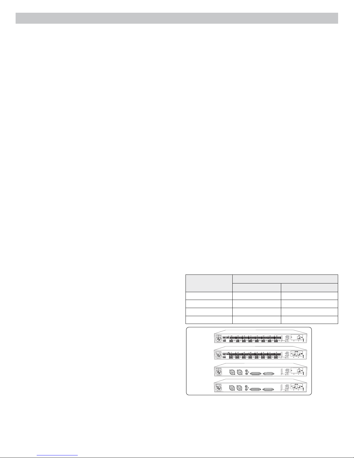
Model Variations
The following table describes the four SCM820 model variations:
+
gateINmute
ovrd
+
direct out
+
gateINmute
ovrd
+
direct out
+
+
gnd
gateINmute
ovrd
gnd
+
+
3
4
direct out
direct out
+
+
gnd
gateINmute
ovrd
gnd
+
+
3
4
direct out
direct out
DIRECT OUTPUTS 1-8
DIRECT OUTPUTS 1-8
Description
INTELLIMIX
CHANNEL
B
A
line
manual
+
gateINmute
ovrd
gnd
gateINmute
ovrd
gnd
A
+0dB
mic
smooth
+30dB
mic
classic
+46dB
CH
B
extreme
+
custom
phm 48 VDC
dual mixer
auto link
2
1
direct out
INTELLIMIX
CHANNEL
B
A
line
manual
+
gateINmute
ovrd
gnd
gateINmute
ovrd
gnd
A
+0dB
mic
smooth
+30dB
mic
classic
+46dB
CH
B
extreme
+
custom
phm 48 VDC
dual mixer
auto link
2
1
direct out
INTELLIMIX
CHANNEL
B
A
line
manual
A
+0dB
mic
smooth
+30dB
mic
classic
+46dB
CH
B
extreme
custom
phm 48 VDC
dual mixer
auto link
INTELLIMIX
CHANNEL
B
A
line
manual
A
+0dB
mic
smooth
+30dB
mic
classic
+46dB
CH
B
extreme
custom
phm 48 VDC
dual mixer
auto link
lockout
reset
00:0E:DD:AA:BB:CC
secondary
primary
lockout
reset
00:0E:DD:AA:BB:CC
lockout
reset
00:0E:DD:AA:BB:CC
secondary
primary
lockout
reset
00:0E:DD:AA:BB:CC
Model
Connector Type Network Card
SCM820 Block Standard Ethernet
SCM820-DAN Block Dante Digital Audio
SCM820-DB25 DB25 Standard Ethernet
SCM820-DAN-DB25 DB25 Dante Digital Audio
AUX IN
OUT
+
+
+
SCM820
SCM820-DAN
SCM820-DB25
SCM820-DAN-DB25
R
L
mix a
+
+
mix b
direct out
AUX IN
OUT
+
R
L
mix a
+
+
mix b
direct out
MIX A
+
gateINmute
ovrd
gnd
gateINmute
ovrd
gnd
gateINmute
ovrd
gnd
gateINmute
ovrd
+
8
direct out
+
gateINmute
ovrd
gnd
+
8
direct out
MIX OUTPUTS
MIX OUTPUTS
gnd
+
+
5
7
6
direct out
direct out
+
+
gateINmute
ovrd
gnd
gateINmute
ovrd
gnd
gateINmute
ovrd
gnd
+
+
5
7
6
direct out
direct out
AUX IN
INPUTS 1-8
L +R
SUM
AUX IN
INPUTS 1-8
L +R
SUM
MIX B
2
Upgrading to Dante
A standard SCM820 can be upgraded with the Dante Network Interface
Card (A820-NIC-DAN) to add full digital audio networking capabilities. This
replaces the standard Ethernet port with two Dante network ports. This
should only be installed by qualified service personnel. Visit www.shure.com
for more details.
Page 5

SCM820 Description
④
SCM820
1 2 3 4 5 6 7 8
gain
low cut
hi shelf
meter
push to solo | hold to mute
①
②
③ ⑦
Front Panel
① Channel Mode Selection
Press the button to select the function of the channel knobs and monitor
LED rings. See the Audio Signal Adjustment section for details on each
mode.
② Assignable Channel Knob
Adjusts settings and status for each input:
Rotate: Adjusts a setting.
Momentary Press: Solos the channel to the headphone output.
Press and Hold: Mutes the audio or bypasses the EQ setting.
③ Monitor LED Ring
13 LED segments display gain setting, input signal meter, IntelliMix gain
meter, channel solo, or EQ setting.
④ Channel Status LED
LED Channel Status
Off Channel is closed (attenuated in the automix).
Green Channel is open (selected in the automix).
Amber Channel EQ is bypassed.
Flicker Red
Solid Red Channel is muted.
⑤ Auxiliary Input Jack (1/8")
Unbalanced aux input sums left and right channels to mono. Front and
back panel aux inputs are summed to a mono signal and routed without
automixing to the mix outputs.
⑥ Master Output Knob
Adjusts settings and status of the mix outputs. See Front Panel Modes for
details.
Rotate: Adjusts output gain or limiter threshold.
Momentary Press: Overrides a soloed channel to return the mix to the
headphone output.
Press and Hold: Mutes the audio or bypasses the limiter.
⑦ Master LED Ring
Displays gain setting or limiter threshold. A single LED represents each
mixer when they are both selected but set to different levels.
⑧ Master Mode Selection
Selects the function (gain or limiter) of the master knob and LED ring.
⑨ Mix Select Button
Selects Mix A, Mix B, or both for adjustment with the master knob and
monitoring on the LED ring and headphone output. Note: When both Mix
A and Mix B are selected, the headphone output only monitors Mix A.
Signal is clipping. Set the channel to a lower input
gain level.
⑤
AUX IN
L+R SUM
⑥
MASTER
⑨
limiter
gain
⑫
LIM
A B
A
0
-9
-18
-24
-36
-48
-60
⑧⑩⑪
⑬
®
IntelliMix
power
B
ethernet
network audio
automix link
dual mixer
lockout
⑭
HEADPHONE
⑮
⑩ Mix Status Indicator
LED Mix Status
Green
Mix is selected for adjustment and listening on the
headphone output.
Amber Limiter is bypassed.
Red Mix is muted.
⑪ Audio Output Meters
Monitor the output signal level and limiter threshold for mix A and B.
LIM (Limiter) LEDs
⑫
Illuminate amber when the audio levels exceed the limiter threshold.
⑬ System Status Indicators
The LEDs illuminate to indicate system settings:
LED Color Status
power Green Unit is powered on.
ethernet Green Unit is connected to a network.
All connected receive channels
Green
are OK (receiving digital audio as
expected).
One or more connected receive
channels experiencing a
network audio
Flashing Green
subscription error or is unresolved
(transmitting device is off,
disconnected, renamed or has
incorrect network setting).
Red Clock synchronization problem.
No receive channels connected
(routing has not been established).
Two or more mixers are connected
in a link group.
automix link
Off
Green
Flashing Green Link Group is configuring.
Off Mixer is in standalone mode.
Green Mixer is set to Dual Mixer operation.
dual mixer
Off
Mixer is set to Single Mixer
operation.
Red Front panel controls are locked.
lockout
Flashing Red
An adjustment is attempted in
lockout mode.
⑭ Headphone Volume Knob
Adjust the volume of the headphone output.
⑮ Headphone Output Jack (1/4 in.)
Monitor a mix or a soloed channel.
3
Page 6
①
+
②
①
②
③ ④ ⑦⑥
OUT
mix a
+
mix b
AUX IN
L
⑤
MIX A
gateINmute
MIX OUTPUTS
+
ovrd
gnd
+
8
direct out
gateINmute
MIX B
+
ovrd
gnd
gateINmute
ovrd
+
7
direct out
AUX IN
L +R
SUM
+
R
+
direct out
③
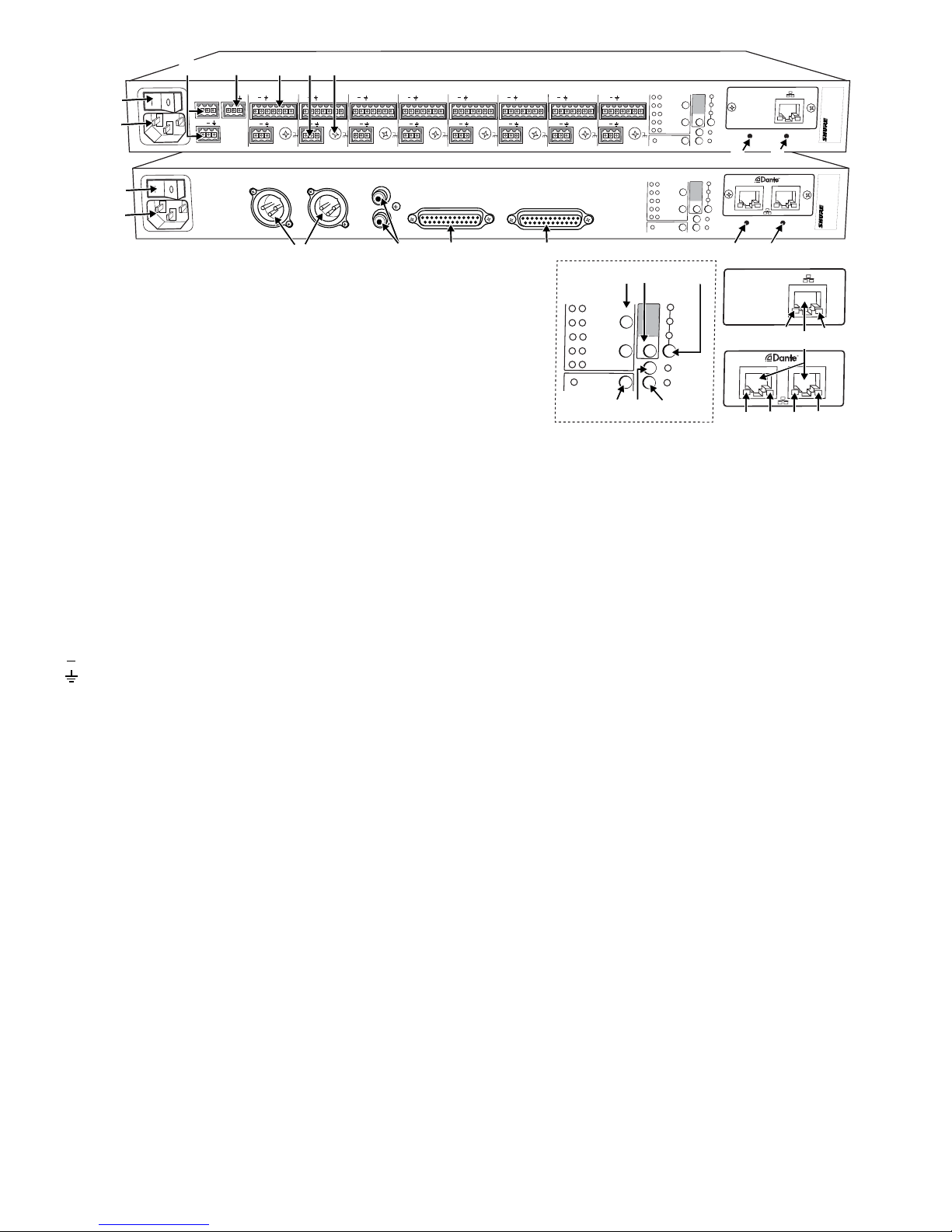
Rear Panel
① Power Switch
Turns the unit on or off.
② AC Power Jack
Supplies AC power to the mixer when plugged into a power source.
gnd
6
④
+
+
direct out
+
gateINmute
ovrd
gnd
+
5
direct out
INPUTS 1-8
⑤ ⑥
INTELLIMIX
CHANNEL
B
A
+
gateINmute
ovrd
gnd
+
4
direct out
+
gateINmute
ovrd
gnd
+
3
direct out
+
gateINmute
ovrd
gnd
+
2
direct out
manual
gateINmute
ovrd
gnd
smooth
classic
extreme
custom
dual mixer
1
line
A
+0dB
mic
+30dB
mic
+46dB
CH
B
phm 48 VDC
lockout
auto link
reset
00:0E:DD:AA:BB:CC
⑭ ⑮
INTELLIMIX
CHANNEL
B
DIRECT OUTPUTS 1-8
A
manual
smooth
classic
extreme
custom
dual mixer
line
A
+0dB
mic
+30dB
mic
+46dB
CH
B
phm 48 VDC
auto link
secondary
primary
lockout
reset
00:0E:DD:AA:BB:CC
⑭ ⑮
INTELLIMIX
B
A
manual
smooth
classic
extreme
custom
dual mixer
⑨
⑧⑩
CHANNEL
A
B
⑫ ⑬
⑪
line
+0dB
mic
+30dB
mic
+46dB
CH
phm 48 VDC
auto link
⑰
secondary
⑱
⑰
⑰
⑯
primary
⑱
⑱
③ Mix A and Mix B Outputs
Active balanced outputs connect to amplifiers, DSP, mixer, or recording
device.
④ Auxiliary Input Jack
Unbalanced aux input sums left and right channels to mono. Front and
back panel aux inputs are summed to a mono signal and routed without
automixing to the mix outputs.
⑤ Channel Inputs 1–8
Active-balanced microphone- or line-level inputs.
Block Connectors
: Audio +
: Audio −
: Audio ground
gate: Logic gate out
mute: Logic mute in
ovrd: Logic override in
gnd: Logic ground
DB25 Connector
Pins: Audio plus, audio negative and audio ground. See Specifications
for details.
⑥ Direct Outputs 1–8
Each channel has a dedicated, impedance-balanced direct output on
the back panel that can be selected from one of five stages in the signal
path. See Configuring the Inputs and Outputs for details on direct output
routing.
⑦ Chassis Ground Screw 1–8
Provides an optional connection for microphone shield wire to chassis
ground.
⑧ IntelliMix Select Buttons
Scrolls through IntelliMix presets for each mix output. When
dual mixer is
off, the A button sets the mode for both Mix A and Mix B.
⑪ Input Gain Selection and LED Indicator
Sets the analog input gain level for the selected channel(s), illuminating
the green LED. All LEDs are off when the channel's audio source is set to
Network from the GUI.
⑫ Phantom Power Button and LED Indicator
Supplies 48 VDC phantom power to the selected channel(s), illuminating
the green LED. Phantom Power is disabled in the line (+0dB) gain setting.
⑬ Auto Link Button and LED Indicator
Enables networked SCM820-DAN mixers to automatically form a link
group. Link Groups enable a larger audio mix by incorporating inputs from
two or more mixers. See Link Groups for more details.
⑭ Lockout Button and LED Indicator
Hold for five seconds to disable front and back panel controls. The front
lockout LED illuminates red (flashing red during an adjustment
panel
attempt) and the back panel channel display shows L.
⑮ Reset Button
Press and hold for five seconds to reboot the mixer with default system
settings restored.
⑯ Network Ports
RJ-45 jacks for network connection.
⑰ Network Status LED (Green)
Off = no network link
On = network link established
Flashing = network link active
⑱ Network Speed LED (Amber)
SCM820:
Off = 10 Mbps
On = 100 Mbps
⑨ Dual Mixer Button
Sets the SCM820 as a dual mixer, indicated by the green LED.
⑩ Channel Select Button and Display
Press to select a single channel (1–8) or all channels (A) when changing
input gain or phantom power.
• When all channels are selected (A), Input Level and Phantom Power
LED indicators only illuminate if all channels have the same setting.
• L is displayed when the mixer is in lockout mode.
4
SCM820-DAN:
Off = 10/100 Mbps
On = 1 Gbps
Page 7
5
IntelliMix Gain
NOMA
Fader
Limiter
IntelliMix Gain
NOMA
EQ
Parametric EQ
IntelliMix A
IntelliMix B
Mute
Control
Routing
(Channel)
Routing
(Aux)
Gating
Logic
Global/Local (Mix)
Audio Source
(Aux)
Audio Source
(Channel)
Global/Local (Aux)
Single/Dual
Mixer
Headphone
Mode
Input Meter
Mode
AUX INPUT
Sum to
Mono
Fader
Master Fader
Direct Output
Selection
Headphone
Mode
Mix
Selection
Mix A Mix B
Input
Trim
Line +0
Mic +26
Mic +46
Left
Right
Left
Right
Dante
Network
L/R
EQ
LIM
A
B
-9
-18
-24
-36
-48
-60
0
D
A
A
D
A
D
A
D
A
D
A
D
D
A
D
A
Sum
Mix A
Sum
Mix B
Sum
Mix A
Sum
Mix B
CHANNEL
INPUTS 1 - 8
Dante
Network
Analog
Back Panel
Analog
Front Panel
Analog
Direct Outputs
(1-8)
Dante
Network
Analog
Mix Outputs
(A and B)
Dante
Network
Aux Output
L/R
Dante
Network
Mix A
A
UX IN
MASTER
lockout
p
o
w
er
ethe
r
net
ne
t
w
o
r
k audio
au
t
omix link
dual mi
x
er
LIM
A
B
-
9
-1
8
-2
4
-3
6
-4
8
-6
0
0
gain
limi
t
er
L+R SUM
gain
l
o
w cut
hi shelf
me
t
er
push to solo | hold to mute
1 2 3 4 5 6 7 8
A
B
HEADPHONE
IntelliMix®
SCM820
A
UX IN
MASTER
lockout
p
o
w
er
ethe
r
net
ne
t
w
o
r
k audio
au
t
omix link
dual mi
x
er
LIM
A
B
-
9
-1
8
-2
4
-3
6
-4
8
-6
0
0
gain
limi
t
er
L+R SUM
gain
l
o
w cut
hi shelf
me
t
er
push to solo | hold to mute
1 2 3 4 5 6 7 8
A
B
HEADPHONE
IntelliMix®
SCM820
A
UX IN
MASTER
lockout
p
o
w
er
ethe
r
net
ne
t
w
o
r
k audio
au
t
omix link
dual mi
x
er
LIM
A
B
-
9
-1
8
-2
4
-3
6
-4
8
-6
0
0
gain
limi
t
er
L+R SUM
gain
l
o
w cut
hi shelf
me
t
er
push to solo | hold to mute
1 2 3 4 5 6 7 8
A
B
HEADPHONE
IntelliMix®
SCM820
A
UX IN
MASTER
lockout
p
o
w
er
ethe
r
net
ne
t
w
o
r
k audio
au
t
omix link
dual mi
x
er
LIM
A
B
-
9
-1
8
-2
4
-3
6
-4
8
-6
0
0
gain
limi
t
er
L+R SUM
gain
l
o
w cut
hi shelf
me
t
er
push to solo | hold to mute
1 2 3 4 5 6 7 8
A
B
HEADPHONE
IntelliMix®
SCM820
A
UX IN
MASTER
lockout
p
o
w
er
ethe
r
net
ne
t
w
o
r
k audio
au
t
omix link
dual mi
x
er
LIM
A
B
-
9
-1
8
-2
4
-3
6
-4
8
-6
0
0
gain
limi
t
er
L+R SUM
gain
l
o
w cut
hi shelf
me
t
er
push to solo | hold to mute
1 2 3 4 5 6 7 8
A
B
HEADPHONE
IntelliMix®
SCM820
A
UX IN
MASTER
lockout
p
o
w
er
ethe
r
net
ne
t
w
o
r
k audio
au
t
omix link
dual mi
x
er
LIM
A
B
-
9
-1
8
-2
4
-3
6
-4
8
-6
0
0
gain
limi
t
er
L+R SUM
gain
l
o
w cut
hi shelf
me
t
er
push to solo | hold to mute
1 2 3 4 5 6 7 8
A
B
HEADPHONE
IntelliMix®
SCM820
A
UX IN
MASTER
lockout
p
o
w
er
ethe
r
net
ne
t
w
o
r
k audio
au
t
omix link
dual mi
x
er
LIM
A
B
-
9
-1
8
-2
4
-3
6
-4
8
-6
0
0
gain
limi
t
er
L+R SUM
gain
l
o
w cut
hi shelf
me
t
er
push to solo | hold to mute
1 2 3 4 5 6 7 8
A
B
HEADPHONE
IntelliMix®
SCM820
Mix B
Link Group Outputs
from other units
Link Group Outputs
to other units
Output Pad
(-0, -20, -46)
Output Pad
(-0, -20, -46)
Mix A
Analog
Sum
Aux L
Sum
Aux R
Mix B
Analog
Digital Feedback
Reducer
DFR
Digital Feedback
Reducer
DFR
Digital Feedback
Reducer
DFR
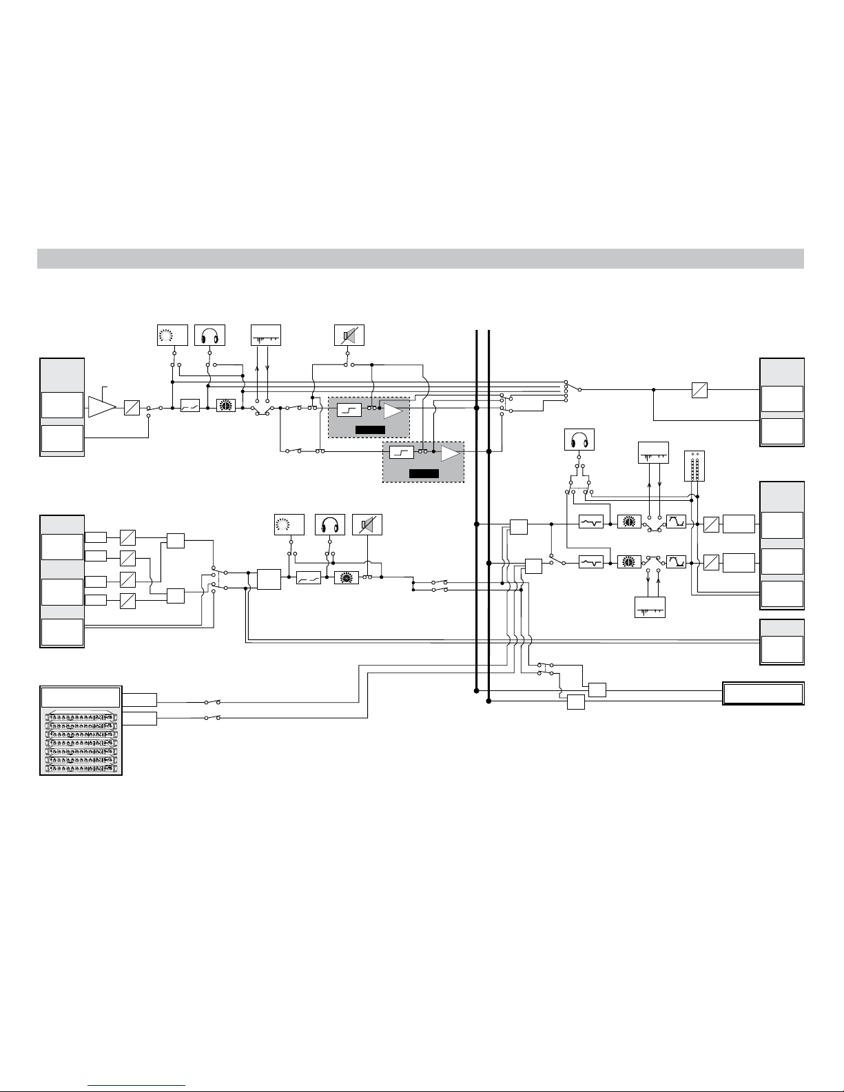
Signal Path Diagram
The following diagram shows the audio signal path and the routing options for several features (default configuration shown). Use the GUI to change the configuration.
Page 8
gain
low cut
hi shelf
ch. meter
i
i
i
i
i
i
i
i
i
i
i
i
i
i
i
i
i
i
i
i
-∞ dB +18 dB
+0 dB
gain
low cut
hi shelf
ch. meter
i
i
i
i
i
i
i
i
i
i
i
i
i
i
i
i
i
i
i
i
gain
low cut
hi shelf
ch. meter
i
i
i
i
i
i
i
i
i
i
i
i
i
i
i
i
i
i
i
i
gain
low cut
hi shelf
ch. meter
i
i
i
i
i
i
i
i
i
i
i
i
i
i
i
i
i
i
i
i
gain
low cut
hi shelf
ch. meter
i
i
i
i
i
i
i
i
i
i
i
i
i
i
i
i
i
i
i
i
320 Hz25 Hz
92 Hz
-60 dBFS 0 dBFS
-∞ dB +18 dB
+0 dB
+12 dB-12 dB
+0 dB
-16 dBFS
gain
low cut
hi shelf
ch. meter
i
i
i
i
i
i
i
i
i
i
i
i
i
i
i
i
i
i
i
i
gain
low cut
hi shelf
ch. meter
i
i
i
i
i
i
i
i
i
i
i
i
i
i
i
i
i
i
i
i
gain
low cut
hi shelf
ch. meter
i
i
i
i
i
i
i
i
i
i
i
i
i
i
i
i
i
i
i
i
gain
low cut
hi shelf
ch. meter
i
i
i
i
i
i
i
i
i
i
i
i
i
i
i
i
i
i
i
i
320 Hz25 Hz
92 Hz
-60 dBFS 0 dBFS
-∞ dB +18 dB
+0 dB
+12 dB-12 dB
+0 dB
-16 dBFS
gain
low cut
hi shelf
ch. meter
i
i
i
i
i
i
i
i
i
i
i
i
i
i
i
i
i
i
i
i
i
i
i
i
i
i
i
i
i
i
i
i
i
i
i
i
i
i
i
i
-80 dB 0 dB
-15 dB
gain
low cut
hi shelf
ch. meter
i
i
i
i
i
i
i
i
i
i
i
i
i
i
i
i
i
i
i
i
gain
low cut
hi shelf
ch. meter
i
i
i
i
i
i
i
i
i
i
i
i
i
i
i
i
i
i
i
i
gain
low cut
hi shelf
ch. meter
i
i
i
i
i
i
i
i
i
i
i
i
i
i
i
i
i
i
i
i
320 Hz25 Hz
92 Hz
-∞ dB +18 dB
+0 dB
+12 dB-12 dB
+0 dB
gain
low cut
hi shelf
ch. meter
i
i
i
i
i
i
i
i
i
i
i
i
i
i
i
i
i
i
i
i
gain
low cut
hi shelf
ch. meter
i
i
i
i
i
i
i
i
i
i
i
i
i
i
i
i
i
i
i
i
320 Hz25 Hz
92 Hz
-∞ dB +18 dB
+0 dB
gain
low cut
hi shelf
i
i
i
i
i
i
i
i
i
i
i
i
i
i
i
i
i
i
i
i
gain
low cut
hi shelf
i
i
i
i
i
i
i
i
i
i
i
i
i
i
i
i
i
i
i
i
gain
low cut
hi shelf
i
i
i
i
i
i
i
i
i
i
i
i
i
i
i
i
i
i
i
i
gain
low cut
hi shelf
i
i
i
i
i
i
i
i
i
i
i
i
i
i
i
i
i
i
i
i
i
i
i
i
i
i
i
i
i
i
i
i
i
i
i
i
i
i
i
i
320 Hz25 Hz
92 Hz
-2 dBFS-50 dBFS
-24 dBFS
-60 dBFS 0 dBFS
-∞ dB +18 dB
-∞ dB +18 dB
+0 dB
+0 dB
+12 dB-12 dB
+0 dB
MASTER
gain
A B
limiter
i
i
i
i
i
i
i
i
i
i
i
i
i
i
i
i
i
i
i
i
MASTER
gain
A B
limiter
-16 dBFS
gain
low cut
hi shelf
i
i
i
i
i
i
i
i
i
i
i
i
i
i
i
i
i
i
i
i
i
i
i
i
i
i
i
i
i
i
i
i
i
i
i
i
i
i
i
i
-80 dB 0 dB
-15 dB
gain
i
i
i
i
i
i
i
i
i
i
i
i
i
i
i
i
i
i
i
i
gain
i
i
i
i
i
i
i
i
i
i
i
i
i
i
i
i
i
i
i
i
gain
i
i
i
i
i
i
i
i
i
i
i
i
i
i
i
i
i
i
i
i
gain
i
i
i
i
i
i
i
i
i
i
i
i
i
i
i
i
i
i
i
i
i
i
i
i
i
i
i
i
i
i
i
i
i
i
i
i
i
i
i
i
320 Hz25 Hz
92 Hz
-60 dBFS 0 dBFS
-∞ dB +18 dB
-∞ dB +18 dB
+0 dB
+0 dB
+12 dB-12 dB
+0 dB
MASTER
gain
A B
limiter
-16 dBFS
gain
i
i
i
i
i
i
i
i
i
i
i
i
i
i
i
i
i
i
i
i
i
i
i
i
i
i
i
i
i
i
i
i
i
i
i
i
i
i
i
i
-80 dB 0 dB
-15 dB
Operating the Mixer
AUX IN
MASTER
lockout
power
ethernet
network audio
automix link
dual mixer
LIM
A
B
-9
-18
-24
-36
-48
-60
0
gain
limiter
L+R SUM
gain
low cut
hi shelf
meter
push to solo | hold to mute
1234567
8
A
B
HEADPHONE
IntelliMix®
SCM820
gain
low cut
hi shelf
meter
push to solo | hold to mute
1 2 3 4 5
IntelliMix®
MASTER
LIM
A
-9
-18
-24
-36
-48
-60
0
gain
limiter
A B
MASTER
lockout
power
ethernet
network audio
automix link
dual mixer
A B
HEADPHONE
SCM820
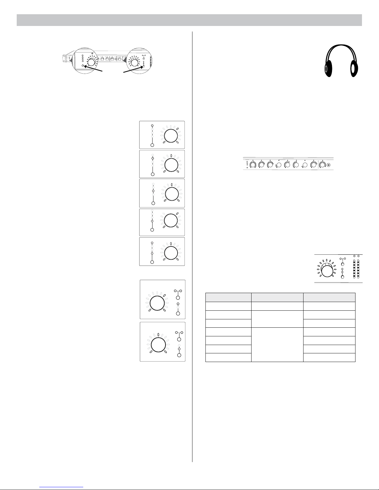
Front Panel Modes
For Channels 1-8
and Aux
Channel Inputs
The channel knobs operate in five modes for different types of input signal
adjustment and display. Use the front panel mode selection button to select
from the following modes.
Channel Gain (gain)
Adjust gain within a 128 dB range while displaying
the gain setting on the LED ring. Unity gain is at the
9th LED.
Mix Outputs
The mix output knob operates in two modes to control
the mix output. Use the master function button to
select one of two modes.
Audio Mute and Bypass
6
Low Cut (
low cut)
Adjust the frequency of the low cut filter (6 dB/octave
from 25 to 320 Hz). Use to remove low-frequency
noise such as table vibrations or air-conditioning
rumble.
High Shelf (
hi shelf)
Adjust the high shelf boost or cut (± 12 dB at 5
kHz). Use to add presence to muddy vocals, temper
sibilant vocals, or enhance the sound of off-axis
lavalier microphones.
Input Signal Meter (
LEDs display the input signal level in real-time.
Channel gain is adjustable in this mode, and will
ch. meter)
momentarily display channel gain setting during
adjustments.
IntelliMix Gain Meter (
LEDs display the IntelliMix attenuation applied
gain and ch. meter)
in realtime. Channel gain is adjustable in this
mode, displaying the setting on the LEDs during
adjustments.
Output Gain (
Rotate to adjust the output gain of the selected mix.
The output signal level is displayed on the meters.
Limiter Threshold (
Rotate to adjust the limiter threshold of the mix (−2
to −50 dBFS). The limiter threshold level is displayed
on the meters.
Mute Channel Input
Press and hold the input channel knob while in gain or ch. meter mode. The
channel status LED turns red.
Mute Mix Output
Press and hold the
turns red.
Bypass Input EQ
Press and hold the input channel knob while in
channel status LED turns amber.
Bypass Output Limiter
Press and hold the
LED turns amber.
gain)
limiter)
MASTER knob while in gain mode. The mix status LED
MASTER knob while in limiter mode. The mix status
Mode
Selector
low cut or hi shelf mode. The
For Mix
Outputs
Monitoring
Headphone Output
Use the front panel headphone jack for monitoring
audio. By default, the headphones monitor the mix prefader/post-EQ (change to post-fader/post-limiter from
GUI > Preferences Tab).
Solo to Headphones
A channel can be soloed to the headphone jack.
Solo Channel: Press a channel knob to solo that channel to the
headphones. The other LED rings dim to highlight the soloed channel.
Exit Solo: Press the soloed channel knob or press the
return the mix to the headphones.
Input Meters
The front panel channel meters can be set to display real-time signal
information. Use the front panel mode selection button to scroll to the
desired mode:
IntelliMix®
1 2 3 4 5 6 7 8
gain
low cut
hi shelf
meter
Input Signal Level
The channel meter mode (
ch. meter) displays real-time audio input signal
level for each channel.
IntelliMix Gain
The IntelliMix meter mode (
gain and ch. meter illuminated) displays
IntelliMix gain operation in real-time across the channel LEDs. Channels
that gate open will display more gain than channels that are closed
(attenuated) in the mix.
Output Meters
The output meters indicate the level of each mix
before the digital-to-analog conversion. By default,
the meter displays average and peak audio levels.
It is good practice to use −18 dBFS on the SCM820
meter as an approximation of 0 VU on an analog
meter.
LED Description Signal Level (dBFS)
Red (7) Clip 0 to -6
Yellow (6)
Yellow (5) -9 to -18
Normal peaks
Green (4)
Green (3) -24 to -36
Green (2) -36 to -48
Signal Present
Green (1) -48 to -60
Changing the Metering Type
Go to the Preferences tab of the GUI to change the following metering
options:
• Meter Type: Change the input and output meters from displaying VU +
Peak (default) to VU or Peak.
• IntelliMix Gain Metering: The Input tab of the GUI can display input
signal level (default) or IntelliMix gain metering in realtime.
-6 to -9
-18 to -24
Master knob to
AUX IN
L+R SUM
LIM
-18
-24
gain
-36
limiter
-48
-60
A
B
0
-9
Page 9
The SCM820 Graphical User Interface
reset
primary
00:0E:DD:AA:BB:CC
SCM820-Dan-ffeee5.local 192.168.200.22
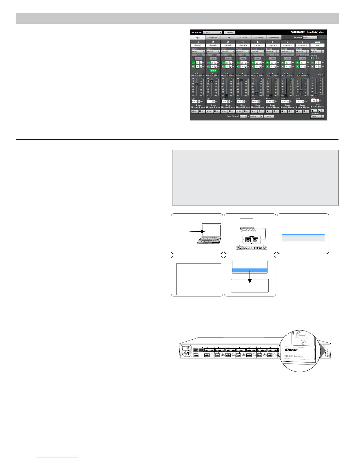
Graphical User Interface (GUI)
The SCM820 graphical user interface (GUI) enables comprehensive
control of the mixer from a web browser. The GUI is hosted from a
webserver embedded on the SCM820, and is accessible from any
computer on the network. Use the GUI for the following functions:
• Manage mixers from a remote location.
• Customize IntelliMix parameters.
• Form large automixes with custom link groups.
• Assign the direct outputs in the signal path.
• Configure Redundant or Split networks.
• Set up and monitor DFR for up to two channels in each mixer.
Accessing the GUI
The Shure Web Server Discovery application finds all Shure devices on
the network that feature a web-based GUI. Follow these steps to install
the software and access the SCM820 GUI:
① Install the Shure Discovery application
Load the Shure USB drive and install the application. This
automatically installs the required Bonjour device discovery tool on
the computer. This application is also available from www.shure.com.
System Requirements
• Windows: Windows XP (32 and 64 bit), Windows Vista and Windows 7
• Apple: Mac OSX 10.6.0 and higher
• Latest version of Adobe Flash Player
• Bonjour software (bundled with the Shure Discovery app)
• The GUI is supported on the following web-browsers: Internet Explorer,
Firefox, Safari and Chrome.
② Connect the network
Ensure the computer and the mixer are on the same network.
③ Launch the Discovery application
The app displays all Shure devices that feature a GUI.
④ Open the SCM820 GUI
Double-click on a device to open its GUI in a web browser.
⑤ Bookmark the GUI (recommended)
Bookmark the device's DNS name to access the GUI without the
Shure Discovery app.
Accessing the GUI without the Discovery App
If the Discovery application is not installed, the SCM820 GUI can be
accessed by typing the DNS name into an internet browser. The DNS
name is derived from model of the unit (SCM820 or SCM820-DAN), in
combination with the last three bytes (six digits) of the MAC address,
and ending in .local.
Format Example: If the MAC address of a unit is 00:0E:DD:AA:BB:CC,
then the link is written as follows:
• SCM820-DAN: http://SCM820-DAN-aabbcc.local
• SCM820: http://SCM820-aabbcc.local
① ② ③
secondary primary
IntelliMix®
1 2 3 4 5 6 7 8
gain
w cut
o
l
hi shelf
er
t
me
push to solo | hold to mute
SCM820
LIM
MASTER
A
B
er
w
o
p
A
B
A
UX IN
HEADPHONE
0
net
ether
-
9
k audio
r
o
w
t
ne
-1
8
omix link
t
au
-2
4
gain
er
x
dual mi
-3
6
limi
t
er
-4
8
L+R SUM
-6
0
lockout
④ ⑤
OUT
AUX IN
+
+
R
L
mix a
+
+
mix b
direct out
+
+
+
+
+
gateINmute
ovrd
gnd
gateINmute
ovrd
gnd
gateINmute
ovrd
gnd
gateINmute
ovrd
gnd
gateINmute
ovrd
+
+
+
7
8
direct out
6
direct out
direct out
gnd
+
+
5
4
direct out
direct out
+
gateINmute
ovrd
gnd
gateINmute
ovrd
gnd
+
+
3
2
direct out
direct out
SCM820-DAN SCM820-Dan-ffeee5.local 192.168.200.22
ROOM 5
CONFERENCE
SCM820
SCM820-ffaaa2.local
192.168.200.23
INTELLIMIX
CHANNEL
B
A
line
manual
A
gateINmute
ovrd
gnd
+0dB
mic
smooth
+30dB
mic
classic
CH
+46dB
B
extreme
secondary
custom
phm 48 VDC
lockout
IntelliMix
dual mixer
direct out
1
Dante
primary
reset
00:0E:DD:AA:BB:CC
7
Page 10
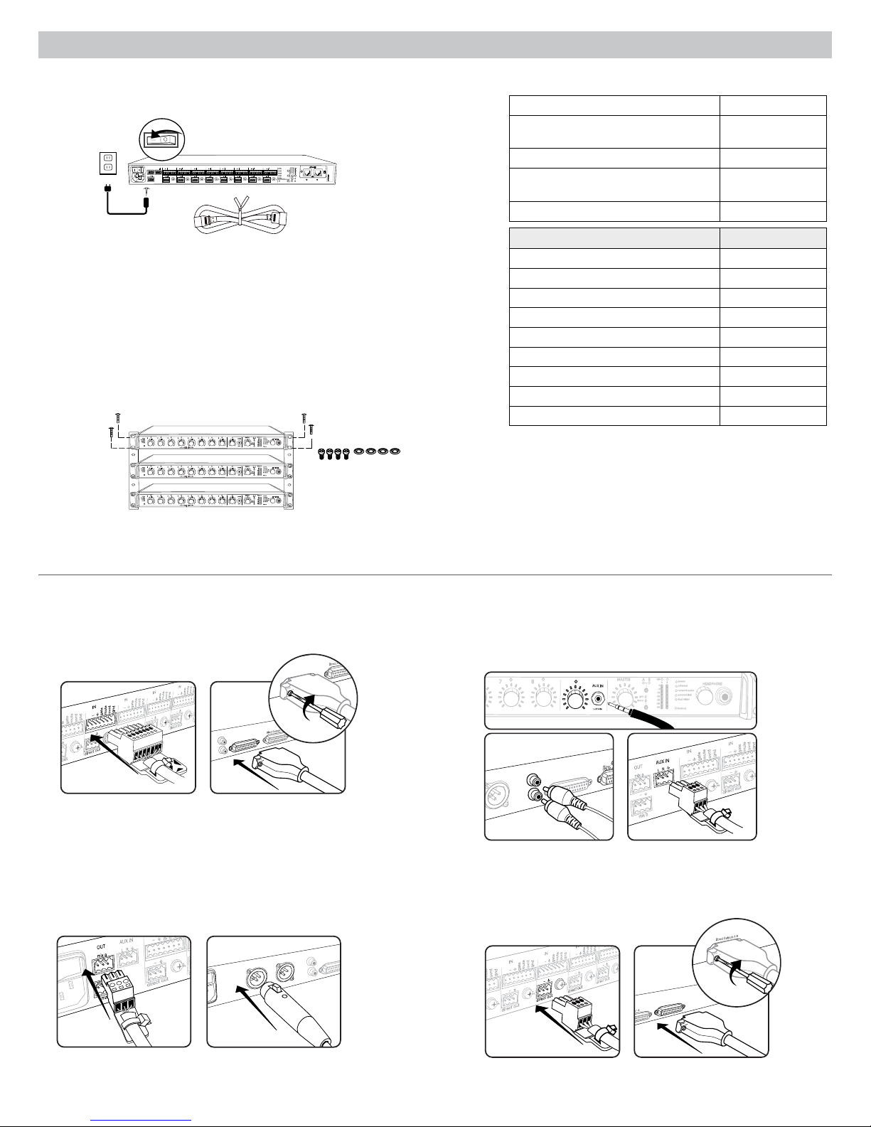
Inputs 1-8
Aux In
L + R
SUM
Inputs 1-8
+
+
+
+
+
+
+
+
6
4
5
3
2
1
+
+
1
+
+
+
+
+
+
+
+
+
+
+
+
+
+
6
4
5
3
2
1
7
8
+
Inputs 1-8
Aux In
MIX OUTPUTS
MIX A
MIX B
L + R
SUM
Inputs 1-8
Aux In
MIX B
L + R
SUM
+
+
+
+
+
+
6
7
8
+
MASTER
lockout
p
o
w
er
ethe
r
net
ne
t
w
o
r
k audio
aut
omix link
dual mi
x
er
LIM
A
B
-
9
-1
8
-2
4
-3
6
-4
8
-6
0
0
gain
limi
t
er
7
8
A
B
HEADPHONE
AUX IN
L+R SUM
Installation
Direct Outputs 1-8
+
+
+
+
+
+
+
+
+
+
6
4
5
3
2
1
+
+
1
7
Power
Connect the unit to AC power using the supplied IEC cable. Turn on the power switch.
INTELLIMIX
OUT
AUX IN
+
+
+
+
+
R
L
mix a
gateINmute
ovrd
gnd
gateINmute
ovrd
gnd
+
+
+
7
8
mix b
direct out
direct out
direct out
+
gateINmute
ovrd
gnd
gateINmute
ovrd
gnd
gateINmute
ovrd
gnd
gateINmute
ovrd
+
6
gnd
+
+
+
5
3
4
direct out
direct out
direct out
CHANNEL
B
A
line
manual
+
+
gateINmute
ovrd
gnd
gateINmute
ovrd
gnd
A
+0dB
mic
smooth
+30dB
mic
classic
CH
+46dB
B
extreme
+
+
secondary
primary
custom
phm 48 VDC
lockout
reset
dual mixer
2
1
direct out
direct out
00:0E:DD:AA:BB:CC
auto link
Rackmounting
Rackmount the mixer using the screws and washers supplied in the Hardware Kit.
Follow these general best practices when rackmounting equipment:
• Ambient temperature of the rack should not exceed specified operating
temperature range of the device.
• Keep fan inlet and side air vents clear from obstructions and provide adequate
space for airflow within the rack.
• When possible, provide 1 RU of empty space between each device.
LIM
MASTER
A
B
er
w
o
p
A
1 2 3 4 5 6 7 8
gain
w cut
o
l
hi shelf
er
t
me
push to solo | hold to mute
1 2 3 4 5 6 7 8
gain
ow cut
l
hi shelf
er
t
me
push to solo | hold to mute
1 2 3 4 5 6 7 8
gain
w cut
o
l
hi shelf
er
t
me
push to solo | hold to mute
B
A
UX IN
HEADPHONE
0
net
r
ethe
-
9
k audio
r
o
w
t
ne
-1
8
omix link
t
au
-2
4
gain
er
x
dual mi
-3
6
limi
t
er
-4
8
L+R SUM
-6
0
lockout
LIM
MASTER
A
B
er
w
o
p
A
B
A
UX IN
HEADPHONE
0
net
r
ethe
-
9
k audio
r
o
w
t
ne
-1
8
omix link
t
au
-2
4
gain
er
x
dual mi
-3
6
limi
t
er
-4
8
L+R SUM
-6
0
lockout
LIM
MASTER
A
B
er
w
o
p
A
B
A
UX IN
HEADPHONE
0
net
r
ethe
-
9
k audio
r
o
w
t
ne
-1
8
omix link
t
au
-2
4
gain
er
x
dual mi
-3
6
limi
t
er
-4
8
L+R SUM
-6
0
lockout
Furnished Accessories
Hardware Kit (SCM820, SCM820-DAN) 90A20082
Hardware Kit (SCM820-DB25,
SCM820-DAN-DB25)
Ethernet cable 95A20437
Power Cable
USB Flash Drive 95A20438
Power Cable by Region Part Number
US 95B8389
Brazil 95A14336
Argentina 95A14335
Europe 95C8247
UK 95A8713
Japan 95B9021
China 95B9073
Korea 95B9074
Australia 95A9128
90BA8100
region dependent,
see table
Typical Audio Connections
① Channel Inputs
• Microphones
• Insert send from a mixer
• Dante network audio
③ Mix Outputs
• Amplifier
• Powered speakers
• Mixer channel inputs
8
② Aux Inputs
Aux-level sound sources:
• MP3 player
• Computer headphone output
• CD player
④ Direct Outputs
• Insert returns to a mixer
• Recording device
• Mixer channel inputs
Page 11

Configuring the Inputs and Outputs
Unless where noted, configurations can be made from the hardware or from the GUI.
Inputs
① Select the Audio Source (GUI only)
• Analog (default): Audio is from a microphone or line-level audio source
connected to a channel input on the mixer back panel.
• Network: Audio is from the Dante digital audio network. Go to the Inputs
tab of the GUI to select Network audio for each desired channel. Dante
Controller software is required to properly route audio to the channel
inputs.
② Select the Input Gain
Select the analog input gain for each channel. No gain is applied for
analog line-level or when the audio source is set to Network.
• Mic (+46dB): For less sensitive microphones, such as dynamics.
• Mic (+26dB): For loud talkers or sensitive microphones such as
condensers.
• Line (+0dB): For line-level sources such as mixer inserts.
③ Supply Phantom Power
Supply 48 V phantom power to the channel when using condenser
microphones. (Phantom power is disabled when Input gain is set to Line.)
④ Adjust Channel EQ
Adjust the high- and low-frequency equalization to improve intelligibility
and reduce undesired noise:
• Low Cut: Ideal for attenuating low-frequency vibration caused by table
vibrations or air-conditioning rumble. Adjust the frequency of the 12 dB/
octave filter from 25 - 320 Hz.
• High Shelf: For tempering sibilant speech or enhancing the sound of offaxis microphones. Use this to boost or cut the signal by 12 dB at 5 kHz
with a slop of 12dB/octave.
Direct and Mix Outputs
⑤ Assign the Direct Outputs (GUI Only)
Assign the Direct Output for each channel from the Output tab of the GUI.
• Pre-EQ: After the Input Gain
• Post-EQ: After the EQ blocks
• Post-Fader: After the channel fader
• IntelliMix: After the IntelliMix gating decision
• IntelliMix NOMA: After IntelliMix gating and NOMA decisions
⑥ Set Mix Output Level (GUI Only)
Set the Output level according to the input of the connecting equipment:
• Line (-0) (default): No attenuation to the output level.
• Aux (-20): The signal is attenuated 20 dB to avoid clipping a line input.
• Mic (-46): The signal is attenuated 46 dB to match a microphone input.
⑦ Set the Limiter
The output limiter prevents distortion during loud program peaks without
affecting normal program levels. This prevents overloading the devices
connected to the mixer outputs.
⑧ Adjust the Output Gain
Adjust the overall output level of the mix.
Auxiliary (Aux) Input
The SCM820 features two auxiliary inputs: an 1/8” jack on the front panel and a back panel input (block connector or RCA connectors, depending on
the model). Each input sums the left and right channel to a mono signal. This mono signal is routed directly to the mix outputs, bypassing the automixing
process. Use this input for sources such as an MP3 player or computer speaker output.
Digital Channels
When the mixer is connected to a Dante network, the left and right channels are accessible before they sum to the mono signal for the mix outputs. Use
the Aux L and Aux R channels in Dante Controller to route audio to and from the aux channel.
9
Page 12

Setting IntelliMix
-15 dB -15 dB
-15 dB
-15 dB
The SCM820 uses IntelliMix to select channels to open in a mix, while attenuating the gain of closed channels. IntelliMix is available in three presets and
can be customized to excel in any application where multiple microphones are used at once. In all modes (except Manual), MaxBus ensures that only one
channel is opened per sound source.
Mixer Mode Descriptions
The SCM820 features five mix modes: Classic, Extreme, Smooth, Custom or Manual.
Classic
Classic mode emulates the classic Shure SCM810 automixer (in its default
settings). It is renowned for fast-acting, seamless channel gating and
consistent perceived ambient sound levels. The Classic mode excels in
most applications, specifically sound reinforcement and teleconferencing.
Gating Style: Full
Gain Scaling: Fixed
Off Attenuation: −15 dB
Last Mic Lock On: Enabled
Smooth
Smooth dynamically balances system gain between open and closed
channels. The system gain remains consistent by distributing gain across
channels to equal one open channel. It incorporates IntelliMix operating
principles into a gain sharing mixing style, making it ideal for broadcast and
recording applications.
Gating Style: Relative
Gain Scaling: Adaptive
Off Attenuation: Disabled
Last Mic Lock On: Disabled
Tip: Unroute all unused channels to the mix bus. This will ensure the
most consistent noise floor in Smooth mode.
Channel Gain in Classic Mixer
1 Talker
Full gain is applied as the
channel opens; off attenuation
gain is applied to all channels.
Channel Gain in Smooth Mixer
1 Talker
-15 dB
Relative gain is applied to the
open channel; all channels
adaptively attenuate to maintain
system gain.
2+ Talkers
-15 dB
As additional channels open,
NOMA factor decreases the
level of all channels.
2+ Talkers
-15 dB
As additional channels open,
gain is adaptively distributed
across all channels to
maintain system gain.
Extreme
Extreme is an aggressive variation of the Classic mode, configured to
achieve maximum gain before feedback by completely attenuating closed
channels. Only open channels add to the system levels and ambient sound.
Extreme mode is designed for sound reinforcement applications.
Gating Style: Full
Gain Scaling: Fixed
Off Attenuation: −110 dB
Last Mic Lock On: Disabled
Manual
Manual mode deactivates IntelliMix to allow the SCM820 to operate as a
standard mixer. All Channel Status LEDs remain on in this mode to indicate
there is no IntelliMix attenuation. Channel and mix equalization, output
limiter and mix bus routing are still active in this setting.
Tip: Be careful when switching to Manual mode, as all microphones will
gate open to full gain, which may result in feedback.
Channel Gain in Extreme Mixer
1 Talker
-15 dB
Full gain is applied to the
open channel. Closed
channels are fully attenuated.
2+ Talkers
As additional channels open,
NOMA factor decreases the
level of all channels.
Custom
Custom mode allows IntelliMix parameters to be fine-tuned and tailored from
the GUI. The mixer automatically switches to Custom once a parameter
is changed in Classic, Extreme or Smooth mode. Theses configurations
are saved to the device and will persist after the mixer is turned off and
restarted. Custom configurations can also be saved as a file to a computer
and loaded onto the device for quick recall.
10
Page 13

4
5
OUT
L
R
mix a
mix b
AUX IN
+
7
+
gateINmute
ovrd
gnd
+
direct out
8
+
gateINmute
ovrd
gnd
+
direct out
6
+
gateINmute
ovrd
gnd
+
direct out
+
gateINmute
ovrd
gnd
+
direct out
+
gateINmute
ovrd
gnd
+
direct out
3
+
gateINmute
ovrd
gnd
+
direct out
2
+
gateINmute
ovrd
gnd
+
direct out
1
+
gateINmute
ovrd
gnd
+
direct out
lockout
line
A
A
B
B
manual
smooth
classic
extreme
custom
dual mixer
+0dB
mic
+30dB
mic
phm 48 VDC
CH
auto link
+46dB
reset
primary
secondary
CHANNEL
INTELLIMIX
00:0E:DD:AA:BB:CC
lockout
line
+0dB
mic
+30dB
mic
phm 48 VDC
CH
auto link
+46dB
reset
primary
secondary
CHANNEL
00:0E:DD:AA:BB:CC
IntelliMix Parameters
Gating Style
Determines the way gain is applied to open channels.
Full
Channels open at full gain (as adjusted by the NOMA factor).
Relative
Channels open at a gain level that varies with the input signal level—
quieter signals receive less gain than loud signals. As the input signal
level increases, more gain is applied to the channel.
Gain Scaling
Determines off attenuation and its effect on the total system gain.
Fixed
Off attenuation is a fixed amount. Total system gain varies with the
number of open channels.
Adaptive
Off attenuation is adjusted to maintain a uniform system gain
comparable to that of a single open channel.
Selecting the Mixer Mode
Press the Mix A or Mix B button on the mixer back panel to scroll
through the five modes. From the IntelliMix tab of the GUI, you can
select a preset or configure the IntelliMix as a Custom setting.
Mixes A and B have the same IntelliMix settings when the
SCM820 is to Single Mixer Operation (default).
Single or Dual Mixer Operation
The mixer can be set to perform one or two automixes:
• Single Mixer (default): Channels are routed to a single mix bus
that sends the same audio to both Mix A and B outputs. Limiter
and master gain can still be set independently for both outputs.
• Dual Mixer: Two separate buses provide independent automixes
for each mix output. In this setting, two entirely different mixes can
result from the same set of inputs.
Enable dual mixer operation by pressing the Dual Mixer button on the
back panel or from GUI > IntelliMix Tab.
Example Dual Mixer Applications:
• Set Mix A to Classic mode for sound reinforcement, and set Mix B
to Smooth for a broadcast feed.
• Mix A to Classic mode for sound reinforcement, and Mix B for
Manual for recording.
• Route channels 1-4 to Mix A and 5-8 to Mix B to run independent
automixes for two different locations from one device.
Off Attenuation
The amount of attenuation applied to closed channels.
Last Mic Lock On
Avoids ambient dropout by keeping at least one channel open at all times.
The last channel opened remains open until another takes its place.
Number of Open Microphones Attenuation (NOMA)
System gain is attenuated as additional channels are opened in a mix. This
is configured per doubling of open channels, adjustable from 1– 6 dB for
each mix that has Gain Scaling set to Fixed.
Maximum Number of Open Microphones (Max NOM)
Restricts the number of microphones that can be open at a time in a mix.
This is adjustable from 1 ("filibuster mode") to maximum (unlimited).
Hold Time
Determines the minimum amount of time that a channel is gated open.
Back Panel
Selecting the Mix Mode
A
B
Press to engage Dual Mixer
operation, illuminating the LED
INTELLIMIX
B
A
manual
smooth
classic
extreme
custom
dual mixer
GUI
operation
Selecting the Mix ModeSelect Dual Mixer
11
Page 14

Networking
Network Overview
For most installations, the SCM820 can connect to a computer either directly
or though a network switch ("Link-Local" connections). Connect multiple
mixers to a switch in a star configuration to ensure reliable networking (each
unit connects directly to the switch).
In some cases, computer settings or programs may interfere with the
network. The majority of these connection issues can be solved by using a
DHCP-enabled router*. Most routers include a DHCP server, while switches
do not.
*Note: DHCP servers are not recommended for redundant network
configurations. See Redundant Network Recommendations for more
details.
Typical Network Setups
IntelliMix®
1 2 3 4 5 6 7 8
gain
w cut
o
l
hi shelf
er
t
me
push to solo | hold to mute
IntelliMix®
gain
1 2 3 4 5 6 7 8
w cut
o
l
hi shelf
er
t
me
push to solo | hold to mute
IntelliMix®
gain
1 2 3 4 5 6 7 8
w cut
o
l
hi shelf
er
t
me
push to solo | hold to mute
IntelliMix®
gain
1 2 3 4 5 6 7 8
w cut
o
l
hi shelf
er
t
me
push to solo | hold to mute
IntelliMix®
gain
1 2 3 4 5 6 7 8
w cut
o
l
hi shelf
er
t
me
push to solo | hold to mute
IntelliMix®
gain
1 2 3 4 5 6 7 8
w cut
o
l
hi shelf
er
t
me
push to solo | hold to mute
IntelliMix®
gain
1 2 3 4 5 6 7 8
w cut
o
l
hi shelf
er
t
me
push to solo | hold to mute
SCM820
LIM
MASTER
A
B
er
w
o
p
A
B
A
UX IN
HEADPHONE
0
net
r
ethe
-
9
k audio
r
o
w
t
ne
-1
8
omix link
t
au
-2
4
gain
er
x
dual mi
-3
6
limi
t
er
-4
8
L+R SUM
-6
0
lockout
SCM820
LIM
MASTER
A
B
er
w
o
p
B
A
A
HEADPHONE
UX IN
0
net
r
ethe
-
9
k audio
r
o
w
t
ne
-1
8
omix link
t
au
-2
4
gain
er
x
dual mi
-3
6
limi
t
er
-4
8
L+R SUM
-6
0
lockout
SCM820
LIM
MASTER
A
B
er
w
o
p
B
A
A
HEADPHONE
UX IN
0
net
r
ethe
-
9
k audio
r
o
w
t
ne
-1
8
omix link
t
au
-2
4
gain
er
x
dual mi
-3
6
limi
t
er
-4
8
L+R SUM
-6
0
lockout
SCM820
LIM
MASTER
A
B
er
w
o
p
B
A
A
HEADPHONE
UX IN
0
net
r
ethe
-
9
k audio
r
o
w
t
ne
-1
8
omix link
t
au
-2
4
gain
er
x
dual mi
-3
6
limi
t
er
-4
8
L+R SUM
-6
0
lockout
SCM820
LIM
MASTER
A
B
er
w
o
p
B
A
A
HEADPHONE
UX IN
0
net
r
ethe
-
9
k audio
r
o
w
t
ne
-1
8
omix link
t
au
-2
4
gain
er
x
dual mi
-3
6
limi
t
er
-4
8
L+R SUM
-6
0
lockout
SCM820
LIM
MASTER
A
B
er
w
o
p
B
A
A
HEADPHONE
UX IN
0
net
r
ethe
-
9
k audio
r
o
w
t
ne
-1
8
omix link
t
au
-2
4
gain
er
x
dual mi
-3
6
limi
t
er
-4
8
L+R SUM
-6
0
lockout
SCM820
LIM
MASTER
A
B
er
w
o
p
B
A
A
HEADPHONE
UX IN
0
net
r
ethe
-
9
k audio
r
o
w
t
ne
-1
8
omix link
t
au
-2
4
gain
er
x
dual mi
-3
6
limi
t
er
-4
8
L+R SUM
-6
0
lockout
Single Mixer
The SCM820 can connect directly to a computer. (This setup may take a
minute or longer to establish a connection between devices.)
Multiple Mixers
Connect multiple mixers together in a star configuration using a DHCPenabled router for the most reliable network setup.
Basic Networking Requirements
To network SCM820 mixers, ensure the setup meets the following
requirements:
• Use shielded Cat5e cables (or higher)
• Cable runs limited to 100 m (328 ft.)
• Devices are on the same subnet
Network Best Practices
• Use gigabit ethernet devices
• Use only one DHCP server per network
• Turn off other network interfaces not used to connect to the mixer
(including WiFi)
• All mixers must have the same level of firmware revision installed
Digital Audio Networking
Dantetm digital audio is carried over standard Ethernet and operates
using standard Internet Protocols. Dante provides low latency, tight clock
synchronization, and high Quality-of-Service (QoS) to provide reliable audio
transport to a variety of Dante devices. Dante audio can coexist safely on
the same network as IT and control data, or can be configured to use a
dedicated network.
Data Types on the Network
The SCM820 transports two types of data over the network: Shure Control
and Dante Audio and Controller. They are transported to/from the two
network ports depending on the mixer's network settings.
Shure Control: The Shure Control carries data for the GUI operation,
firmware updates and 3rd party control systems (AMX, Crestron). This
network is supported by all SCM820 models.
Dante Audio and Controller: The Dante network carries both the digital
audio and the control data for Dante Controller. This network is supported
by Dante-enabled SCM820s.
Switch Recommendations for Dante Networking
In addition to the basic networking requirements, Dante audio networks should
use a Gigabit network switch or router with the following features:
• Gigabit ports
• Quality of Service (QoS) with 4 queues
• Diffserv (DSCP) QoS, with strict priority
• Recommended: A managed switch to provide detailed information about the
operation of each network link (port speed, error counters, bandwidth used)
Dante Network Interface
The Dante network card is a two-port interface
that can be configured to enable the following
applications:
• Link mixers to expand the audio mix, enabling the addition of up to 12
mixers (96 channels).
• Protect the audio signal with a redundant audio network.
• Isolate Dante audio from the Shure Control network.
• Record audio to a computer without additional hardware.
• Maintain digital audio path to other Dante devices.
• Route an 8-channel automixing insert to another Dante device using a
single shielded Cat5e cable.
• Daisy-chain up to four SCM820 mixers.
secondary primary
12
Page 15

A
UX IN
MASTER
lockout
p
o
w
er
ethe
r
net
ne
t
w
o
r
k audio
au
t
omix link
dual mi
x
er
LIM
A
B
-
9
-1
8
-2
4
-3
6
-4
8
-6
0
0
gain
limi
t
er
L+R SUM
gain
l
o
w cut
hi shelf
me
t
er
push to solo | hold to mute
1 2 3 4 5 6 7 8
A
B
HEADPHONE
IntelliMix®
SCM820
A
UX IN
MASTER
lockout
p
o
w
er
ethe
r
net
ne
t
w
o
r
k audio
au
t
omix link
dual mi
x
er
LIM
A
B
-
9
-1
8
-2
4
-3
6
-4
8
-6
0
0
gain
limi
t
er
L+R SUM
gain
l
o
w cut
hi shelf
me
t
er
push to solo | hold to mute
1 2 3 4 5 6 7 8
A
B
HEADPHONE
IntelliMix®
SCM820
A
UX IN
MASTER
lockout
p
o
w
er
ethe
r
net
ne
t
w
o
r
k audio
au
t
omix link
dual mi
x
er
LIM
A
B
-
9
-1
8
-2
4
-3
6
-4
8
-6
0
0
gain
limi
t
er
L+R SUM
gain
l
o
w cut
hi shelf
me
t
er
push to solo | hold to mute
1 2 3 4 5 6 7 8
A
B
HEADPHONE
IntelliMix®
SCM820
A
UX IN
MASTER
lockout
p
o
w
er
ethe
r
net
ne
t
w
o
r
k audio
au
t
omix link
dual mi
x
er
LIM
A
B
-
9
-1
8
-2
4
-3
6
-4
8
-6
0
0
gain
limi
t
er
L+R SUM
gain
l
o
w cut
hi shelf
me
t
er
push to solo | hold to mute
1 2 3 4 5 6 7 8
A
B
HEADPHONE
IntelliMix®
SCM820
A
UX IN
MASTER
lockout
p
o
w
er
ethe
r
net
ne
t
w
o
r
k audio
au
t
omix link
dual mi
x
er
LIM
A
B
-
9
-1
8
-2
4
-3
6
-4
8
-6
0
0
gain
limi
t
er
L+R SUM
gain
l
o
w cut
hi shelf
me
t
er
push to solo | hold to mute
1 2 3 4 5 6 7 8
A
B
HEADPHONE
IntelliMix®
SCM820
A
UX IN
MASTER
lockout
p
o
w
er
ethe
r
net
ne
t
w
o
r
k audio
au
t
omix link
dual mi
x
er
LIM
A
B
-
9
-1
8
-2
4
-3
6
-4
8
-6
0
0
gain
limi
t
er
L+R SUM
gain
l
o
w cut
hi shelf
me
t
er
push to solo | hold to mute
1 2 3 4 5 6 7 8
A
B
HEADPHONE
IntelliMix®
SCM820
A
UX IN
MASTER
lockout
p
o
w
er
ethe
r
net
ne
t
w
o
r
k audio
au
t
omix link
dual mi
x
er
LIM
A
B
-
9
-1
8
-2
4
-3
6
-4
8
-6
0
0
gain
limi
t
er
L+R SUM
gain
l
o
w cut
hi shelf
me
t
er
push to solo | hold to mute
1 2 3 4 5 6 7 8
A
B
HEADPHONE
IntelliMix®
SCM820
A
UX IN
MASTER
lockout
p
o
w
er
ethe
r
net
ne
t
w
o
r
k audio
au
t
omix link
dual mi
x
er
LIM
A
B
-
9
-1
8
-2
4
-3
6
-4
8
-6
0
0
gain
limi
t
er
L+R SUM
gain
l
o
w cut
hi shelf
me
t
er
push to solo | hold to mute
1 2 3 4 5 6 7 8
A
B
HEADPHONE
IntelliMix®
SCM820
A
UX IN
MASTER
lockout
p
o
w
er
ethe
r
net
ne
t
w
o
r
k audio
au
t
omix link
dual mi
x
er
LIM
A
B
-
9
-1
8
-2
4
-3
6
-4
8
-6
0
0
gain
limi
t
er
L+R SUM
gain
l
o
w cut
hi shelf
me
t
er
push to solo | hold to mute
1 2 3 4 5 6 7 8
A
B
HEADPHONE
IntelliMix®
SCM820
A
UX IN
MASTER
lockout
p
o
w
er
ethe
r
net
ne
t
w
o
r
k audio
au
t
omix link
dual mi
x
er
LIM
A
B
-
9
-1
8
-2
4
-3
6
-4
8
-6
0
0
gain
limi
t
er
L+R SUM
gain
l
o
w cut
hi shelf
me
t
er
push to solo | hold to mute
1 2 3 4 5 6 7 8
A
B
HEADPHONE
IntelliMix®
SCM820
A
UX IN
MASTER
lockout
p
o
w
er
ethe
r
net
ne
t
w
o
r
k audio
au
t
omix link
dual mi
x
er
LIM
A
B
-
9
-1
8
-2
4
-3
6
-4
8
-6
0
0
gain
limi
t
er
L+R SUM
gain
l
o
w cut
hi shelf
me
t
er
push to solo | hold to mute
1 2 3 4 5 6 7 8
A
B
HEADPHONE
IntelliMix®
SCM820
secondary primary
secondary primary
secondary primary
secondary primary
secondary primary
secondary primary
secondary primary
A
UX IN
MASTER
lockout
p
o
w
er
ethe
r
net
ne
t
w
o
r
k audio
au
t
omix link
dual mi
x
er
LIM
A
B
-
9
-1
8
-2
4
-3
6
-4
8
-6
0
0
gain
limi
t
er
L+R SUM
gain
l
o
w cut
hi shelf
me
t
er
push to solo | hold to mute
1 2 3 4 5 6 7 8
A
B
HEADPHONE
IntelliMix®
SCM820
Network Modes
The Dante network interface can be configured to operate in one of three modes: Switched, Redundant Audio or Split. This setting determines the types of
data that are transported from the Primary and Secondary ports.
Data Transport in each Mode
The following table displays the configuration of the Dante network ports in each Network Mode. Note: Always connect the Primary port to the network that is
used for Shure Control.
Dante Port Configuration
Network Mode
Switched (default)
Shure Control
Dante Audio and Controller
Secondary Primary
Redundant Audio Dante Redundant Audio
Split Dante Audio and Controller Shure Control Isolate Dante and Shure Control networks
Caution: Disconnect the equipment from the network prior to changing the network mode. This will avoid a network loop that will make the network unstable.
Selecting the Network Mode
1. Disconnect the mixer from the network.
2. Connect the Primary port of the mixer directly to a computer.
3. Go to the Network panel in the GUI:
Preferences > Network
4. Select the Configuration mode. The mixer will reboot once the selection is confirmed.
5. Repeat for each mixer.
Warning: Do not reconnect mixers to the network until the network configuration is the same for all units.
Port Function
Shure Control
Dante Audio and Controller
Shure Control
Dante Audio and Controller
Application
Typical installations of star or daisy-chained networks.
Create a backup audio network.
Network Configurations in Switched Mode (default)
Star Configuration (Recommended)
Connect multiple mixers to a router in a star
configuration for the most reliable setup.
Daisy-Chain (up to 4)
Up to four SCM820-DAN mixers can
network together by daisy-chain. This is
only supported in Switched network mode
(default).
Direct to Computer
Connect the Primary port directly to a
computer.
Warning: Do Not Make a Network Loop
Avoid the following setups that will render the
network unusable:
Star Configuration
(Recommended)
secondary primary
secondary primary
secondary primary
secondary primary
secondary primary
secondary primary
IntelliMix®
gain
1 2 3 4 5 6 7 8
w cut
o
l
hi shelf
er
t
me
push to solo | hold to mute
IntelliMix®
gain
1 2 3 4 5 6 7 8
w cut
o
l
hi shelf
er
t
me
push to solo | hold to mute
IntelliMix®
gain
1 2 3 4 5 6 7 8
w cut
o
l
hi shelf
er
t
me
push to solo | hold to mute
IntelliMix®
gain
1 2 3 4 5 6 7 8
w cut
o
l
hi shelf
er
t
me
push to solo | hold to mute
IntelliMix®
gain
1 2 3 4 5 6 7 8
w cut
o
l
hi shelf
er
t
me
push to solo | hold to mute
IntelliMix®
gain
1 2 3 4 5 6 7 8
w cut
o
l
hi shelf
er
t
me
push to solo | hold to mute
Daisy-Chain Direct to Computer
secondary primary
secondary primary
secondary primary
SCM820
secondary primary
LIM
MASTER
A
B
er
w
o
p
B
A
A
HEADPHONE
UX IN
0
net
r
ethe
-
9
k audio
r
o
w
t
ne
-1
8
omix link
t
au
-2
4
gain
er
x
dual mi
-3
6
limi
t
er
-4
8
L+R SUM
-6
0
lockout
SCM820
LIM
MASTER
A
B
er
w
o
p
B
A
A
HEADPHONE
UX IN
0
net
r
ethe
-
9
k audio
r
o
w
t
ne
-1
8
omix link
t
au
-2
4
gain
er
x
dual mi
-3
6
limi
t
er
-4
8
L+R SUM
-6
0
lockout
SCM820
LIM
MASTER
A
B
er
w
o
p
B
A
A
HEADPHONE
UX IN
0
net
r
ethe
-
9
k audio
r
o
w
t
ne
-1
8
omix link
t
au
-2
4
gain
er
x
dual mi
-3
6
limi
t
er
-4
8
L+R SUM
-6
0
lockout
SCM820
LIM
MASTER
A
B
er
w
o
p
B
A
A
HEADPHONE
UX IN
0
net
r
ethe
-
9
k audio
r
o
w
t
ne
-1
8
omix link
t
au
-2
4
gain
er
x
dual mi
-3
6
limi
t
er
-4
8
L+R SUM
-6
0
lockout
SCM820
LIM
MASTER
A
B
er
w
o
p
B
A
A
HEADPHONE
UX IN
0
net
r
ethe
-
9
k audio
r
o
w
t
ne
-1
8
omix link
t
au
-2
4
gain
er
x
dual mi
-3
6
limi
t
er
-4
8
L+R SUM
-6
0
lockout
SCM820
LIM
MASTER
A
B
er
w
o
p
B
A
A
HEADPHONE
UX IN
0
net
r
ethe
-
9
k audio
r
o
w
t
ne
-1
8
omix link
t
au
-2
4
gain
er
x
dual mi
-3
6
limi
t
er
-4
8
L+R SUM
-6
0
lockout
IntelliMix®
1 2 3 4 5 6 7 8
gain
w cut
o
l
hi shelf
er
t
me
push to solo | hold to mute
IntelliMix®
1 2 3 4 5 6 7 8
gain
w cut
o
l
hi shelf
er
t
me
push to solo | hold to mute
IntelliMix®
1 2 3 4 5 6 7 8
gain
w cut
o
l
hi shelf
er
t
me
push to solo | hold to mute
IntelliMix®
1 2 3 4 5 6 7 8
gain
w cut
o
l
hi shelf
er
t
me
push to solo | hold to mute
SCM820
LIM
MASTER
A
B
er
w
o
p
A
B
A
UX IN
HEADPHONE
0
net
r
ethe
-
9
k audio
r
o
w
t
ne
-1
8
omix link
t
au
-2
4
gain
er
x
dual mi
-3
6
limi
t
er
-4
8
L+R SUM
-6
0
lockout
SCM820
LIM
MASTER
A
B
er
w
o
p
A
B
A
UX IN
HEADPHONE
0
net
r
ethe
-
9
k audio
r
o
w
t
ne
-1
8
omix link
t
au
-2
4
gain
er
x
dual mi
-3
6
limi
t
er
-4
8
L+R SUM
-6
0
lockout
SCM820
LIM
MASTER
A
B
er
w
o
p
B
A
A
UX IN
HEADPHONE
0
net
r
ethe
-
9
k audio
r
o
w
t
ne
-1
8
omix link
t
au
-2
4
gain
er
x
dual mi
-3
6
limi
t
er
-4
8
L+R SUM
-6
0
lockout
SCM820
LIM
MASTER
A
B
er
w
o
p
A
B
A
UX IN
HEADPHONE
0
net
r
ethe
-
9
k audio
r
o
w
t
ne
-1
8
omix link
t
au
-2
4
gain
er
x
dual mi
-3
6
limi
t
er
-4
8
L+R SUM
-6
0
lockout
secondary primary
IntelliMix®
1 2 3 4 5 6 7 8
gain
w cut
o
l
hi shelf
er
t
me
push to solo | hold to mute
secondary primary
secondary primary
SCM820
LIM
MASTER
A
B
er
w
o
p
A
B
A
UX IN
HEADPHONE
0
net
r
ethe
-
9
k audio
r
o
w
t
ne
-1
8
omix link
t
au
-2
4
gain
er
x
dual mi
-3
6
limi
t
er
-4
8
L+R SUM
-6
0
lockout
secondary primary
Do not connect the
primary to the secondary
port of the same device.
secondary primary
Do not connect the two ports
to the same switch.
secondary primary
secondary primary
Do not connect mixers
together in a loop.
13
Page 16

A
UX IN
MASTER
lockout
p
o
w
er
ethe
r
net
ne
t
w
o
r
k audio
au
t
omix link
dual mi
x
er
LIM
A
B
-
9
-1
8
-2
4
-3
6
-4
8
-6
0
0
gain
limi
t
er
L+R SUM
gain
l
o
w cut
hi shelf
me
t
er
push to solo | hold to mute
1 2 3 4 5 6 7 8
A
B
HEADPHONE
IntelliMix®
SCM820
A
UX IN
MASTER
lockout
p
o
w
er
ethe
r
net
ne
t
w
o
r
k audio
au
t
omix link
dual mi
x
er
LIM
A
B
-
9
-1
8
-2
4
-3
6
-4
8
-6
0
0
gain
limi
t
er
L+R SUM
gain
l
o
w cut
hi shelf
me
t
er
push to solo | hold to mute
1 2 3 4 5 6 7 8
A B
HEADPHONE
IntelliMix®
SCM820
A
UX IN
MASTER
lockout
p
o
w
er
ethe
r
net
ne
t
w
o
r
k audio
au
t
omix link
dual mi
x
er
LIM
A
B
-
9
-1
8
-2
4
-3
6
-4
8
-6
0
0
gain
limi
t
er
L+R SUM
gain
l
o
w cut
hi shelf
me
t
er
push to solo | hold to mute
1 2 3 4 5 6 7 8
A B
HEADPHONE
IntelliMix®
SCM820
A
UX IN
MASTER
lockout
p
o
w
er
ethe
r
net
ne
t
w
o
r
k audio
au
t
omix link
dual mi
x
er
LIM
A
B
-
9
-1
8
-2
4
-3
6
-4
8
-6
0
0
gain
limi
t
er
L+R SUM
gain
l
o
w cut
hi shelf
me
t
er
push to solo | hold to mute
1 2 3 4 5 6 7 8
A B
HEADPHONE
IntelliMix®
SCM820
Redundant and Split Networks
The Primary and Secondary ports require dedicated network switches in
Redundant Audio and Split modes.
Disable DHCP
secondary primary
secondary primary
secondary primary
secondary primary
Isolated Networks for Each Port in
Redundancy and Split Modes
Redundant Network Recommendations
For the most reliable Redundant network, it is recommended to set up both
networks without a DHCP server. Connect each unit to a network switch
without DHCP or to a router with DHCP disabled.
If it is not possible to disable the DHCP server, configure the mixer to a
static IP address from the GUI (
Note: Use caution when operating a Link Group in a Redundant
network. If a Link Group goes down, there will be temporary audio loss
on both ports while the group reconfigures.
GUI > Preferences tab > IP Mode > Manual).
Configuring a 100 Mbps Dante network
Gigabit equipment is strongly recommended for Dante network. If this is not
possible, configure the 100 Mbps network with the following guidelines:
• Ensure the router has QoS enabled
• Latency settings are set to at least 1 ms
Caution: Do not form Link groups on a 100Mbps network, as this will
cause increased traffic and will exceed the network bandwidth.
Setting Latency
Latency is the amount of time for a signal to travel across the system to
the outputs of a device. To account for variances in latency time between
devices and channels, Dante has a predetermined selection of latency
settings. When the same setting is selected, it ensures that all Dante
devices on the network are in sync.
The latency setting for Dante devices should be set according to the number
of switches in the network. The SCM820 network card has an internal switch
chip and counts as a switch. For example, one SCM820 connected to an
external switch equals two switches.
Go to
GUI > Preferences Tab to change the setting.
Latency Recommendations
Latency Setting
0.25 ms 3 -
0.5 ms (default) 5 1 ms 10 2
2 ms 10+ 5
*Strongly Recommended
Maximum Number of Switches
1 Gbps Network* 100 Mbps Network
Dante Software by Audinate
Audinate software provides additional function and control of the Dante digital audio network. Visit Audinate's website at www.audinate.com for software
installation instructions, additional digital audio networking capabilities and troubleshooting help.
Dante Virtual Soundcard
Dante Virtual Soundcard (DVS) software turns a computer into a Danteenabled device, allowing digital audio traffic to be transmitted and received
using the standard Ethernet port.
On Windows, DVS can select Steinberg’s ASIO audio interface or Windows
Driver Model (WDM). On Mac OSX, the DVS uses the standard Core Audio
interface.
DVS License
Shure provides a free DVS license with the Dante-enabled SCM820
Automatic Mixer (SCM820-DAN) and the Dante Network Interface Card
(A820-NIC-Dante). Use your DVS Token on the Audinate website to obtain a
single computer License ID for Dante Virtual Soundcard. Without a License
ID, the software will not work.
Follow these steps to begin using Dante Virtual Soundcard:
1. Locate your DVS token on the half-page card supplied with the unit.
2. Go to http://www.audinate.com/RedeemDVSToken
3. If not already logged in, you will be asked to log in or register
4. Enter the DVS Token string in the field provided
Once validated, a page will be displayed with the following information:
• Your Dante Virtual Soundcard License ID
• Links to follow to download the Dante Virtual Soundcard and Dante
Controller applications
Dante Controller
Dante Controller (DC) is a free software program by Audinate that is used to
configure and manage a network of Dante devices. Use it to route channels
between Dante-enabled devices and to monitor the status of the device,
clock, and network.
For proper functionality with the SCM820, use Dante Controller version
3.4.0.0 or higher. Go to Audinate's website for download and installation
instructions.
14
Page 17

4
5
OUT
L
R
mix a
mix b
AUX IN
+
7
+
gateINmute
ovrd
gnd
+
direct out
8
+
gateINmute
ovrd
gnd
+
direct out
6
+
gateINmute
ovrd
gnd
+
direct out
+
gateINmute
ovrd
gnd
+
direct out
+
gateINmute
ovrd
gnd
+
direct out
3
+
gateINmute
ovrd
gnd
+
direct out
2
+
gateINmute
ovrd
gnd
+
direct out
1
+
gateINmute
ovrd
gnd
+
direct out
lockout
line
A
A
B
B
manual
smooth
classic
extreme
custom
dual mixer
+0dB
mic
+30dB
mic
phm 48 VDC
CH
auto link
+46dB
reset
CHANNEL
INTELLIMIX
primary
secondary
00:0E:DD:AA:BB:CC
4
5
OUT
L
R
mix a
mix b
AUX IN
+
7
+
gateINmute
ovrd
gnd
+
direct out
8
+
gateINmute
ovrd
gnd
+
direct out
6
+
gateINmute
ovrd
gnd
+
direct out
+
gateINmute
ovrd
gnd
+
direct out
+
gateINmute
ovrd
gnd
+
direct out
3
+
gateINmute
ovrd
gnd
+
direct out
2
+
gateINmute
ovrd
gnd
+
direct out
1
+
gateINmute
ovrd
gnd
+
direct out
lockout
line
A
A
B
B
manual
smooth
classic
extreme
custom
dual mixer
+0dB
mic
+30dB
mic
phm 48 VDC
CH
+46dB
reset
CHANNEL
INTELLIMIX
00:0E:DD:AA:BB:CC
auto link
Application Examples
lockout
line
+0dB
mic
+30dB
mic
phm 48 VDC
CH
auto link
+46dB
reset
CHANNEL
primary
secondary
00:0E:DD:AA:BB:CC
lockout
line
+0dB
mic
+30dB
mic
phm 48 VDC
CH
+46dB
reset
CHANNEL
00:0E:DD:AA:BB:CC
auto link
lockout
line
+0dB
mic
+30dB
mic
CH
+46dB
reset
CHANNEL
00:0E:DD:AA:BB:CC
Creating a Link Group
If additional channels are needed, multiple mixers can link together to create
a larger automatic mix. To form a link, Dante-enabled mixers are connected
to a gigabit network and assigned to a link group. This enables up to 12
mixers (96 channels) to contribute to the same mix from anywhere on the
network.
Mixers in the same link group operate under shared IntelliMix settings.
These settings are defined by the first mixer to join the group. When mixers
are added, their IntelliMix and network settings are reconfigured to match
the group's settings. IntelliMix settings can then be changed from any mixer,
automatically updating the rest of the group.
Setting up a Link Group
Link Groups are managed from the Link Group tab of the GUI. Once a mixer
joins a group, its front panel Network Audio and Automix Link LEDs will
illuminate green. Up to 12 mixers can join a group at a time.
Ensure the Link Group setup meets the following requirements:
• Use SCM820 mixers with the Dante network card (SCM820-DAN or
SCM820-DAN-DB25)
• Devices must be on the same subnet
• Use Gigabit (or higher) network switches to connect the devices. 100 Mb
networks are not supported.
• Ensure the switches have at least 300 Mbps of available bandwidth for
each device. Devices in a Link Group use more network bandwidth than
Stand Alone devices.
Automatic Linking
The auto link setting enables SCM820s to automatically form a link group
when they join the network. No additional setup from the GUI is required.
Select the
other mixers with this function enabled. Mixers with auto linking enabled will
display in the Auto Link group in the GUI.
auto link button on the mixer back panel. It automatically links to
Note: Only the first 12 mixers that enable Auto-Link will join the group. If
the group is full and an additional mixer attempts to enable Auto Link, it
will remain as a Stand-Alone device.
MIX OUTPUTS
AUX IN
INPUTS 1-8
L +R
SUM
Enable
Auto-Linking
DIRECT OUTPUTS 1-8
INTELLIMIX
CHANNEL
B
A
line
manual
A
+0dB
mic
smooth
+30dB
mic
classic
+46dB
CH
B
extreme
custom
phm 48 VDC
reset
lockout
dual mixer
auto link
phm 48 VDC
auto link
Setting Mix Outputs in a Link Group
The Local/Global setting determines whether each linked SCM820 Mix
Output contains only its own program output, or that of all linked mixers. Go
to the Output tab of the GUI to select the mix output.
Note: The Master level control is independent of the Local/Global
setting. The output level and limiter setting of each mixer is affected only
by its own Master control.
Global (default): All linked channels appear at the mixer outputs. This is
the default setting for the mixer.
Local: Only its own eight input channels appear at the mixer's Mix Outputs.
Aux Channel
The aux channel can be set to Local or Global from GUI > Inputs Tab.
Local Aux keeps the Aux signal from appearing on the mix output of other
networked boxes
Integrating with Other Systems
DFR or External Equalizer
When using DFR channels or setting up a sound system an external
processor/equalizer, begin by setting the SCM820 to Manual. This activates
(gates open) all channels, so every possible feedback path is open.
After equalizing the sound system and "ringing out" the room with the
feedback controller, set the mixer back to an IntelliMix mode.
Shure ULX-D Digital Wireless System
Shure ULX-D™ Digital Wireless offers uncompromising audio clarity and
extremely efficient RF performance with rugged, intelligent, encryptionenabled hardware. The SCM820-DAN can provide automixing for the Dual
or Quad ULX-D receiver by connecting to the Dante digital audio network.
As Channel Inserts
IntelliMix can be used as a processing insert on an analog console or over
the digital audio network. Be sure to set the console inserts to post-fader.
If this is not available, be sure to mute audio at the SCM820 in order to
remove the signal from the automix.
Analog Insert
1. Connect the send from the mixer insert to the input of the SCM820.
2. Set the channel input to Line level (+0).
3. Connect return from the mixer insert to the direct output of the
SCM820.
4. Set the direct output to IntelliMix NOMA.
00:0E:DD:AA:BB:CC
Dante Insert
1. Open Dante Controller software.
2. Route the console sends to the SCM820 inputs.
3. Route the SCM820 direct outputs to the console returns.
4. Set the channel Source to Network from the Inputs tab of the GUI.
5. Set the direct output to IntelliMix NOMA on the Outputs tab.
Custom Groups
To configure specific Link Groups, create a custom group in the GUI.
Custom groups are helpful for managing multiple Link Groups across
multiple mixers on the same network. To set up a Custom Group:
1. Open the Link Group tab of the GUI.
2. Click the New Group button create a group.
3. Name the group.
4. Drag and drop mixers to the group.
SCM820-1
SCM820-2
SCM820-3
SCM820-4
SCM820-5
SCM820-6
Group 1
SCM820
SCM820-1
SCM820-3
SCM820-4
SCM820-5
SCM820-6
Configuring for Use with a Choir
Use the SCM820 to manage a group of microphones that are providing
sound reinforcement for a choir.
1. Connect microphones to the mixer.
2. Set the appropriate level for the microphones.
3. Open the IntelliMix tab of the GUI.
4. Select Classic IntelliMix mode.
5. Engage the Gate Group box for each choir microphone to ensure they
gate open and closed at the same time. This will change the IntelliMix to
Custom mode.
6. Increase the Hold Time for the Mix output to the maximum setting of 1500
ms.
Tip: If unnatural gating occurs during sustained notes, disable the Noise
Adaptive Threshold (NAT) and manually set a gate threshold.
15
Page 18

Internet Calling
Dante-enabled mixers integrate software applications such as Skypetm,
Lynctm, Voice. This enables multiple microphones to participate in a
teleconferencing event.
1. Reference the Installation section to properly connect and setup
microphones to the mixer back panel.
2. Open the IntelliMix tab of the GUI.
3. Select Dual Mixer operation.
4. In the GUI, route channels 1 - 8 to Mix A only (deselect routing to Mix B).
5. In the Inputs tab, set the Aux channel to Network input source.
6. Route the Aux channel to Mix B only.
7. Open Dante Virtual Soundcard and turn it on.
8. Open Dante Controller (DC) software.
9. In DC, route the SCM820 tx channel 'Mix A' to computer rx channel 1.
10. In DC, route computer tx channels 1 and 2 to SCM820 rx channels Aux
L and R.
11. Connect Mix B analog output to a speaker or output device.
12. Open the computer's settings and select Dante as the input and output
soundcard.
Trademarks: Trademarks are the property of their respective owners.
Logic
The logic functions of the SCM820 expand the mixer's range of installation
and control options. These functions can be hardwired or configured in the
GUI.
The following hardware logic functions are available for each channel:
Gate Out
Follows channel gating and goes to logic "low" (sinks current) when
microphone is gated on. 500 mA of current sinking ability is provided.
Mute In
Applying logic "low" (from GATE OUT or a switch closure to logic ground)
gates channel off (channel output is fully attenuated).
Override In
Applying logic "low" (from GATE OUT or a switch closure to logic ground)
forces channel on. When both Mute and Override are activated, Mute
takes precedence.
Logic Ground
Logic ground is distinct from the SCM820 audio ground. Make all logic
ground connections to this pin, including power supply ground of external
logic circuitry. To avoid switch clicks, do not connect logic ground to audio,
chassis or rack grounds.
Suggested Logic Application
This section contains suggestions on the uses of the SCM820's logic
capabilities. For additional suggestions and solutions to installation
problems, contact Shure's Systems Support.
Cough Button
The talker can turn off his or her microphone during coughing or private
conversations by installing an SPST pushbutton switch between the MUTE
IN and Logic Ground pins for each channel to be modified. When a channel
is muted, no audio is passed.
Set the mute control to post-IntelliMix setting (
> Mute Control) to ensure that unwanted sounds do not gate on other
microphones.
Chairperson-Controlled Muting
The chairperson can, by activating a switch, silence all other microphones
and be heard without interruption.
1. Set the desired channel to Chairperson Mute to manual (
IntelliMix Panel > Chairperson > Mute).
2. Connect the switch to the Override In logic connection for the
chairperson's microphone.
An alternative to a switch is to set the Chairperson Mute to Auto. In this
setting, when the chairperson's microphone activates, all other microphones
mute automatically.
GUI > IntelliMix Panel
GUI >
Remote Channel-Open Indicators
Remote indicators can be used to indicate when a talker's microphone
is on. Connect the LEDs and a 5-volt supply to the GATE OUT pin. To
avoid switching clicks in the audio output, do not ground the power supply
negative terminal in the audio system or rack ground.
Important: If a single cable is used for the microphone audio signal and the
LED dc power, separate shielded pairs must be used. Failure to carry the
DC power on a shielded pair may result in audible clicking due to capacitive
coupling between the DC power lines and microphone lines.
Disabling the Gating Function (Always On)
Select Always On for the channel(s) that should remain open (
IntelliMix Panel > Always On.
Inhibiting Gating for Unwanted Sounds
The MaxBus operating principle ensures that the mixer will activate only one
microphone per sound source. Muting a microphone channel prevents its
audio from appearing at the mixer's output. However, the muted channel set
to Post-IntelliMix still communicates with other mic channels via MaxBus.
A sound source picked up by a muted microphone will not activate other
microphones.
Sound sources that may cause unwanted microphone channel activation
include:
• A noisy fax machine or printer
• A squeaky door
• An intercom system
• A teleconferencing loudspeaker
The SCM820 can prevent these and similar sounds from activating
microphones by taking the following steps.
1. Place one microphone near the unwanted sound source. Connect that
microphone's signal to a channel input.
2. Mute the channel.
3. Set the Mute Control to Post-IntelliMix (
4. Adjust that channel's gain control just to the level where other
microphones in the system do not activate for the unwanted sound. If the
channel gain is set too high, other system microphones will be difficult to
activate for desired sounds. If set too low, unwanted sounds will continue
to activate other microphones.
Loudspeaker Muting
Some applications require a loudspeaker to be placed near each talker
to provide audio reinforcement, or to permit telephone conversation or
conference monitoring. Each loudspeaker can cause feedback unless it is
automatically switched off when the talker near it speaks. To provide this
function, connect the GATE OUT terminal of each channel to a separate
loudspeaker muting relay.
NOTE: A diode across each relay coil is required to suppress inductive
voltage spikes which may damage the SCM820.
An alternative to creating a circuit is a Logic Controlled Relay, such as the
Radio Design Labs (RDL) ST-LCR1.
“Filibuster” Mode
In normal operation, when several people talk, each microphone gates on
so that no speech is missed. In “filibuster” action, a microphone that is gated
on prevents other microphones from gating on. Once a microphone has
gated on, other microphones cannot gate on until the talker has paused long
enough for that microphone to gate off. Thus the person talking has the floor
and cannot be interrupted.
Set the maximum number of open microphones to 1 (
Mix A/B > Max NOM
GUI > IntelliMix Tab > Mute Control).
GUI > IntelliMix Panel >
GUI >
16
Page 19

Digital Feedback Reduction (DFR)
DFR uses Shure’s patented Adaptive Notch Filter algorithm to
discriminate between feedback and non-feedback sounds. It
automatically detects feedback and deploys narrow-band notch filters
at the feedback frequencies. DFR filters are narrow enough to prevent
any coloration of the audio program.
No sound system (the combination of microphones, mixing, signal
processing, power amplifiers, loudspeakers and room acoustics)
produces an absolutely flat response. When the level of a sound
system is increased, the frequencies at which peaks occur will be the
first to exceed the threshold of feedback. The DFR attenuates these
frequencies, flattening the response of the sound system and enabling
operation at a higher overall level.
DFR is available for the SCM820 on firmware versions 1.1.0 and
higher. For a unit running an earlier firmware version, use the Shure
Update Utility application to update the mixer to a new firmware. The
application is available from www.shure.com/software.
Function
Use DFR as the initial processor on any channel that receives signal
from a live microphone where feedback is problematic. When DFR
detects feedback, it inserts a shallow, narrow filter into the audio
path to reduce gain at the feedback frequency. This filter is called a
notch filter, due to the narrow section of the frequency spectrum it
affects. The notch automatically deepens if feedback continues on that
frequency.
Basic DFR Setup
Digital Feedback Reducer will not enable you to increase system gain
beyond the physical limits of the sound system. In most cases, you reach
a point of diminishing returns after five to eight notch filters are set. This
is because there are usually only a few dominant peaks in the response
of the system. In most cases, you can expect a 6 dB to 9 dB improvement
in gain-before-feedback by using the DFR. When you are ringing out the
system and notice that many frequencies feedback simultaneously, you
have reached the point of diminishing returns. If at this point the system still
has insufficient gain before feedback, other changes must be made to the
sound system, such as changing the placement of the microphones and/or
loudspeakers.
There are two basic ways in which to set-up the DFR to reduce feedback;
the Ring-Out Method and the Insurance Policy Method:
• Ring Out Method - With this method, you use the DFR as a preemptive
measure against feedback for input channels that operate near the
feedback point and need an extra margin of stability. Using this
method, you raise the channel’s gain beyond its normal setting to
deliberately make the system feed back. The DFR will then set the
proper filters. Then, when you reduce the input gain to an appropriate
level, the system is stable and usable.
• Insurance Policy Method - With this method, you use the DFR as
added insurance against unexpected feedback in an otherwise stable
system. Simply place the DFR processor in the signal path, without
defining any settings. This method is used for systems which already
have sufficient gain-before-feedback, but need protection from
occasional feedback occurrences due to non-stationary microphones or
user-adjustable gain controls.
To ring out the system:
1. Remove any active filters by clicking the Clear All button.
2. Place microphones at their intended locations.
3. Set the mixer to Manual to open all mics.
4. Slowly raise the gain of the sound system while talking or clapping into
the microphones.
5. Assign the DFR to the channel that begins to feed back. If multiple
microphones feed back in the same frequency, assign the DFR to the
mix bus.
6. The DFR processor will deploy notch filters to attenuate the feedback
frequencies.
7. Once the system has stopped feeding back, you can continue by further
raising the level and repeating the process for additional frequencies.
Typically you can raise the gain 3 dB to 9 dB above the level at which
feedback first occurred.
8. Lock the deployed filters so they are fixed. The remaining Unlocked
(Dynamic) filters will deploy as needed when the system is in use.
Note: Depending on the setup of the sounds system, the main PA signal
may be separate from the monitor mix signal. Each feedback path should
include a DFR for the maximum gain before feedback.
17
Page 20

Assigning DFR
⑥ ⑦ ⑧ ⑨
⑩
⑪
⑫
⑬
⑭
④
③②
Two DFR blocks are assignable to any channel input or mix output. When using two or
less microphones, assign the DFR to those channels to prevent feedback from routing to
the mix bus. Additionally, if a microphone is designated for a chairperson or host, DFR
should be applied to that channel to ensure that remains stable and does not feed back.
Apply DFR to a mix bus when using multiple non-stationary microphones or when
trouble frequencies are feeding back simultaneously in multiple microphone channels.
Filter Types
By default, the DFR processor filters are unlocked to dynamically adjust as feedback
frequencies are detected. However, you can specify how many of the total number of
notch filters will remain fixed (locked). Use a greater number of locked (fixed) filters
on input channels for stationary microphones. In this instance, the room acoustics
define the dominant feedback frequencies, which do not change appreciably. Use a
greater number of the dynamic (unlocked) filters on input channels for wireless or handheld microphones. In this situation, feedback frequencies change drastically as the
microphone user wanders the room or sound stage.
Both fixed and dynamic filters will automatically deepen as additional feedback is
detected.
• Locked (Fixed): Once set, the frequency of a fixed filter will not change until it has
been cleared or a new frequency manually entered.
• Unlocked (Dynamic): Frequencies are automatically assigned by the DFR as
feedback is detected. Once a filter is deployed, it remains at that frequency until all
filters are used. At that time, the DFR redeploys each dynamic filter at the newly
detected frequency, in the order of oldest dynamic filter to newest.
Filter Width
The DFR offers two width options for notch filters. By default, filters in the DFR are
deployed as High Q filters. As a high Q filter gets deeper its Q increases up to 101
(1/70th of an octave). You can also set filters to deploy at Low Q. Low Q filters affect a
slightly wider range of frequencies by maintaining a Q of 58 (1/40th of an octave) as they
deepen. To change the setting for an existing filter, select the Q-Width drop-down menu
in the filter row.
New Filter Q: This setting determines the Q width for new Unlocked (Dynamic)
frequencies as deployed by DFR.
18
Page 21

Navigation Bar
⑤
④
②
③
GUI Description
①
1) Tabs
The GUI is separated into six tabs that are used for different functions:
• Input: Setup and management of input channels 1-8 and Aux
• IntelliMix: Select Mix mode and load/save Customize IntelliMix settings
• DFR: Set up and monitor Shure Digital Feedback Reducer (DFR) for up to two channels
• Output: Assign the direct output and manage Mix A and Mix B outputs
• Link Group: Manage the Link Group status of devices
• Preferences: Configure network settings, set the device password, assign metering type, and engage hardware lockout.
2) Device List
Displays the name of the mixer as set in the Preferences tab. Click the drop-down bar and select a device to open its GUI in a new window or tab.
3) Identify
When clicked, this commands the mixer’s LEDs to flash for easy identification.
4) Log Off
When a password is set, this button logs off of the device and returns the user to the Log On page. This button does not appear when there is no password
(default).
5) Shure Web Link
Links to the Shure website at www.shure.com.
6) Language
Sets the language of the GUI. This setting is saved to the computer’s cookies.
7) Help
Opens the Help file for the GUI.
⑥
⑦
19
Page 22

Input Tab
⑤
⑥
⑦
⑧
⑪
⑫
⑬
⑭
①
②
③
⑮
⑯
⑰
④
⑨
⑩
1) Channel Name
Channel names can be customized with up
to 31 any characters in length except ‘=’,’.’ or
‘@’.
2) Source
Sets the audio input to one of two sources:
• Analog (default): Audio is from a microphone
or line-level audio source connected to a
channel input on the mixer back panel.
• Network: Audio is from the Dante digital
audio network. Dante Controller software
is required to properly route audio to the
channel inputs.
3) Input Gain Level
Selects the analog input gain level for each
channel.
• Mic (+46 dB): For less sensitive
microphones such as dynamics.
• Mic (+26 dB): For loud talkers or sensitive
microphones such as condensers.
• Line (+0dB): For line-level sources such as
mixer inserts.
Note: Gain is disabled when the audio source
is set to Network.
4) Phantom Power (+48V)
When selected, the button illuminates green
to indicate 48 V phantom power is supplied
to the microphone. Use this setting for
condenser microphones.
Note: Disabled when Input Gain Level is set
to Line (+0dB) or Network is selected for the
audio source .
5) Low Cut Button
Ideal for attenuating low-frequency vibration
caused by table vibrations or air-conditioning
rumble. Adjust the frequency of the 12 dB/
octave filter from 25 - 320 Hz.
• Green= enabled
• Gray= disabled
6) High Shelf Button
For tempering sibilant speech or enhancing
the sound of off-axis microphones. Use this to
boost or cut the signal by 12 dB at 5 kHz.
• Green= enabled
• Gray= disabled
7) DFR Enable/Disable Button
When Digital Feedback Reducer (DFR) is
assigned from the DFR tab, an enable/disable
button appears in that channel strip.
• Green= enabled
• Gray= disabled
8) Channel On Indicators
The two indicators illuminate green when
the channel is open to that mix bus (Mix A or
Mix B). When set to Dual Mixer, the A and B
indicators function separately for each mix.
9) Clip Indicator
Illuminates when the signal is clipping the
input preamp. The light will stay lit as a
warning for 2 seconds. Select a lower Input
Gain Level to avoid clipping.
10) Input Meter
Displays signal level information. The meter
is customizable in the Preferences tab to
monitor the following options:
• Realtime monitoring of the input signal level
(default) or IntelliMix Gain attenuation.
• Pre- or post-fader Input signal level.
• VU + Peak (default), Peak, or VU metering
of input signal level_Ref86959235.
11) Channel Fader and Gain Value
Adjusts the channel volume from -110 dB to
+18 dB.
12) Group (Fader and Mute)
Each channel can join a fader or mute group,
which enable the adjustment of several
channels at once. There is one Fader and one
Mute group for each Link Group.
13) Mute Button
Mutes the audio for that channel. A muted
channel still can still be soloed to the
headphones for monitoring. Channel Mute
Control can be set to one of two places from
the IntelliMix tab:
• Pre-IntelliMix: Audio is muted before
MaxBus or IntelliMix decisions.
• Post-IntelliMix: Audio is muted after
contributing to IntelliMix and Maxbus
decisions.
14) Solo Button
Solos the selected channel to the headphone
jack for monitoring.
15) Aux Routing
Routes the aux channel to the selected
mix output. The aux channel routes without
automixing to the mix outputs.
16) Aux Link Mode
Defines the aux channel routing when the
device is in a Link Group:
• Global (default): Aux audio appears at the
outputs of all linked mixers.
• Local: Aux audio appears only at that
mixer’s output.
17) Copy Channel
Copies the selected channel’s Input settings
to the device or to the entire Link Group.
20
Page 23

Intellimix Tab
④
③
①
⑤
⑥
⑦
⑧
⑨
⑩
⑪
⑫
⑬
⑭
②
⑮
⑯
⑰
⑱
⑲
⑳
21
22
23
Mixer Settings
1) Mixer Type
The SCM820 can be set to operate as a single or dual mixer:
• Single Mixer: Channels are routed to a single mix bus that sends the
same audio to both Mix A and B outputs. This allows the same program
to be sent to different rooms or recording applications. The output gain,
parametric equalizer and limiter can be set separately for each mix.
• Dual Mixer: Two separate buses provide independent automixes for
each mix output. This allows two entirely different mixes to result from
the same set of inputs or enables the SCM820 to function as two
smaller independent mixers. This is useful when the mixer is being
used for two applications. For example, set Mix A to Classic mode for
sound reinforcement, and set Mix B to Smooth for a broadcast feed. As
a dual mixer, each channel can route to Mix A, Mix B, both or neither
mixes.
2) Mix Modes
The Mix Mode sets the IntelliMix configuration to determine the way the
channels are mixed to the master outputs. When an adjustment is made
to any IntelliMix preset, the mode automatically changes to Custom. See
Mixer Modes section for configuration details of each preset.
Press the mode button to highlight which channels are routed to that mix.
The color of the box around a channel correlates to the IntelliMix settings
of the mix output. To view the other mix’s settings, click on the mode for
that mix.
Note: When set to Single Mixer operation, Mixes A and B are the same.
3) Save
Saves current Custom IntelliMix settings as a file to your computer.
4) Load
Uploads a saved Custom IntelliMix settings file.
Channel Strip
5) Channel Name
Displays the channel name as defined in the Inputs Tab.
6) Routing
Routes the channel to the Mix A or Mix B output. The routing options
depend on the Mixer Type:
• Single Mixer Type: the channel can route to both or neither mixes.
• Dual Mixer Type: the channel can route to Mix A, Mix B, both, or
neither mixes.
7) Gating Logic
When the mixer is set to Dual Mixer operation, this setting determines
whether Mix A or Mix B controls the hardware functions (IntelliMix Direct
Output), indicators (Channel Status LEDs) and channel Logic pins.
8) Always On
The Always On setting forces a channel to stay open continuously in the
mix.
Note: A channel that is set to Always On still contributes to and is affected
by the IntelliMix. For example, NOMA still applies to Always On channels.
9) NAT (Noise Adaptive Threshold)
Select to engage the NAT, which continuously adjusts the gate threshold
for opening a channel. NAT is a core IntelliMix operating principle.
10) Offset
Sets the difference in dBs between the noise floor (determined by NAT)
and a signal level, above which will open a channel.
11) Threshold
When NAT is deactivated, this manually determines the noise level above
which a channel will gate open.
12) Chairperson
Override: When selected, it allows this channel to gate open regardless of
NOM setting (number of open microphones).
Mute: When selected, all other channels mute when this channel gates
open. There are two types of Chairperson Mute:
• Auto: Other channels automatically mute when the selected channel is
gated open.
• Manual: A Logic-wired button connected to the Override In Logic pin
controls the mute function applied to all other channels.
13) Gate Group
When any channel from the group is gated open, the rest of the group
automatically gates open. There is one Gate Group for each Link Group.
In Dual Mix mode, there is one gate group per Mix for each Link Group.
This is disabled when the Gating Style is set to Relative.
21
Page 24

①
④
③
②
⑤
⑥
⑦
⑧
⑨
⑩
⑪
⑫
⑬
⑭
14) Mute Control
Determines the location of a channel mute in the mixer’s signal path.
• Pre-IntelliMix: the signal mutes prior to the Intellimix bus.
• Post-IntelliMix: the signal goes to the mix bus and is muted after it
contributes to IntelliMix decisions (such as MaxBus and NOM).
Mix Outputs
15) Mix Name
Displays Mix Output name, set from the Mix Output tab.
16) Gating Style
Determines the way gain is applied to open channels.
• Full: Channels open at full gain, adjusted to the NOMA factor.
• Relative: Channels open at a gain level that varies with the input signal
level—quieter signals receive less gain than loud signals.Note: Gate
Group and Hold Time are disabled in this setting.
17) Gain Scaling
Determines how total system gain is managed. There are two types of
Gain Scaling:
• Fixed: Off attenuation is a fixed amount. Total system gain varies with
the number of open channels.
• Adaptive: Off attenuation is adjusted to maintain a uniform system gain
comparable to that of a single open channel. Note: Off Attenuation, Last
Mic Lock-On, and NOMA are disabled in this setting.
18) Off Attenuation
Sets the amount of attenuation applied to closed channels. This is
disabled when the Gain Scaling is set to Adaptive.
⑮
⑯
⑰
⑱
⑲
⑳
21
22
23
19) Hold Time
In Full gating style, this determines how long a channel remains open
after the signal level drops below the gate threshold. This is disabled
when the Gating Style is set to Relative.
20) NOMA (Number of Open Microphone Attenuation)
NOMA attenuates the system gain as additional channels open in a
mix. This controls system levels and reduces feedback. The parameter
setting applies per doubling of microphones. This is disabled when the
Gain Scaling is set to Adaptive.
21) MAX NOM (Number of Open Microphones)
Limits the maximum number of microphones that can be open in a mix at
the same time. When set to Max, there is no limit.
Tip: Set the MAX NOM to 1 for “Filibuster Mode” (one talker at a time).
22) LMLO (Last Mic Lock On)
Avoids ambient dropout by keeping at least one channel open at all
times (the last opened channel).This is disabled when the Gain Scaling
is set to Adaptive.
23) Copy Channel
Copies the selected channel’s IntelliMix settings to the device or to the
entire Link Group.
22
Page 25

Digital Feedback Reduction (DFR) Tab
①
⑥ ⑦ ⑧ ⑨
⑤
⑬
③②
⑩
⑪
⑫
⑭
④
⑮
1) Enable/Disable Button
Click this button to enable or disable the
DFR notch filtering. It automatically turns on
when DFR is assigned to a channel. When
disabled, the DFR filters are turned off.
• Green= enabled
• Gray= disabled
2) Channel Assignment
Assign the DFR block to an input channel or
mix bus.
3) # of Filters
Adjust the maximum number of filters from 1
to 16 (default).
4) Response Graph
This curve is a graphical representation of the
processor’s active notch filters (highlighted
in yellow). The frequency of the currently
selected filter is indicated by a red line.
5) Feedback Filters
Each filter row displays the filter type,
frequency, depth and Q width. Between 1 and
16 filters are available for each DFR channel.
When a row is selected, a red line appears on
the response curve at that frequency.
6) Filter Type
This button designates the filter type so
that its frequency either dynamically adjusts
or remains fixed. In both types, DFR
automatically adjusts the filter depth.
• Unlocked (Dynamic): the frequency is
adjusted automatically
• Locked (Fixed): the frequency is fixed and
will not change automatically
7) Frequency
This indicates the frequency of the selected
filter. You can change the value by scrolling
on the arrow buttons or by entering a specific
value. The frequency range is from 25Hz to
20kHz. The value is blank (------) until the filter
is deployed by the DFR or entered manually.
8) Depth
This indicates the gain reduction of the
selected filter. The range of available gain
values is between 0 db and -18 dB in 0.5 dB
increments, with a default setting of 0 dB.
9) Q-Width
This indicates the bandwidth type of the
selected filter. Select High Q (default) or Low
Q from the drop-down menu.
• High Q: 1/70th octave (Q=101)
• Low Q: 1/40 octave (Q=58)
10) New Filter Q
This selection designates the width of each
new filter as it is deployed by DFR.
11) Freeze
Click this button to prevent both the
deployment of new filters and the automatic
adjustment of existing filters. Freeze the DFR
to keep it from deploying filters for program
material that contains sounds that closely
resemble feedback (such as guitar effects,
synthesized tones, flute or pipe organ). The
button appears lighted in blue when the freeze
feature is enabled. During this time, filters
remain manually adjustable.
12) Auto Clear
This feature automatically clears Unlocked
(Dynamic) filters and removes changes to the
depth of Locked (Fixed) filters. Locked filter
depth reverts to the level set when Auto Clear
was enabled.
When enabled, Auto Clear occurs during each
power cycle. Additionally, a repeating timeout
can be defined to ensure that DFR filters clear
regularly.
The Auto Clear timeout applies to each filter
independently, and starts the moment it is
deployed. The timer will restart after any change
to a filter’s frequency, depth, or Q. The timer has
a range of 1 minute to 100 hours.
13) Clear Filter Buttons
• Selected: Clears settings for the selected
filter(s).
• Unlocked: Clears settings for all Unlocked
(Dynamic) filters.
• Clear All: Clears all settings in the DFR
block and reverts all filters back to Unlocked
(Dynamic).
14) Load/Save
All DFR parameters can be saved as a file to a
computer and loaded to quickly recall settings.
Note: DFR settings are included with SCM820
system settings that are saved from the
Preferences tab.
15) Channel Fader and Gain Value
Channel gain is adjustable from to the DFR tab
for monitoring the notch filters when ringing out a
sound system. Any adjustment made to the gain
here is mirrored on the assigned channel strip.
23
Page 26

Output Tab
⑱
①
②
③
④
⑤
Direct Output
1) Channel Name
Displays the channel name as defined in the Inputs Tab.
2) Direct Output Selection
The direct output can be routed from one of five stages in the signal path:
• Pre-EQ (default): After the Input Gain
• Post-EQ: After the EQ blocks
• Post-Fader: After the channel fader
• IntelliMix: After the IntelliMix gating decision
• IntelliMix NOMA: After IntelliMix gating and after NOMA is applied
3) Direct Output On Indicator
The two indicators the gating states that are used for the direct outputs.
4) Clip Indicator
Illuminates when the input signal overloads the digital-to-analog
converter. The light will stay lit as a warning for 2 seconds.
5) Direct Output Meter
Displays the channel’s direct output signal level.
Master
6) Mix Output Name
Mix names can be customized with up to 31 any characters in length
except ‘=’,’.’ or ‘@’.
7) PEQ (Parametric Equalizer)
Each mix output has an 8-band parametric EQ that is engaged by the
check box. Press the button to open the PEQ window.
8 bands are editable from the PEQ, including a low and high shelf. Select
the box to engage the band and edit the following parameter:
• Frequency: Sets the center frequency for each band from 25 - 20,0000
Hz.
• Width and Q: This setting adjusts the bandwidth of the EQ adjustment
from very narrow (1/70 octave or 100.99Q) to very wide (4 octaves or
0.27 Q).
• Gain: Sets boost or cut of the EQ setting from -18 to +18 dB.
8) DFR Enable/Disable Button
When DFR is assigned from the DFR tab, an enable/disable button
appears in that channel strip.
• Green= enabled
• Gray= disabled
⑥
⑦
⑧
⑨
⑩
⑪
⑫
⑬
⑭
⑮
⑯
⑰
9) Lim (Limiter) Indicator
Illuminates to indicate that the signal has exceed the limiter threshold,
engaging the limiter.
10) Clip Indicator
Illuminates when the signal has clipped the outputs, holding for two
seconds.
11) Output Meter
Displays the output signal level.
12) Fader and Gain Value Box
Adjusts the mix volume from -110 dB to +18 dB.
13) Limiter Activation Box
Activates the limiter when selected.
14) Limiter Threshold
Set the limiter threshold from -2 to -50 dBFS for the mix outputs. The
level is indicated by the blue triangle next to the meter.
15) Output Level
Selects the output level of the mix outputs. Set according to the input of
the connecting equipment. There are three settings: Line (-0dB) (default),
Aux (-20dB), Mic (-46dB).
16) Group (Fader or Mute)
Adds the mix to the Fader or Mute group. Groups allow the adjustment of
several mixes outputs at once. There is one Fader and one Mute group
per Link Group.
17) Mute
Mutes the audio output for that mix.
18) Link Mode
Defines the audio content for the mix outputs when the device is in a Link
Group.
• Global (default): The mixer’s outputs contain audio from the entire Link
Group.
• Local: The mixer’s outputs contains only the audio from that mixer’s
inputs.
24
Page 27

Link Group Tab
SCM820
SCM820-1
SCM820-2
SCM820-3
SCM820-4
SCM820-5
SCM820-6
Auto
Group 1
SCM820
SCM820-1
②
①
④
1) All Devices List
Master list of all available SCM820 Dante units on the network.
• Drag and drop the devices to a Link Group or the Stand Alone Window.
• Select a device to view its location in either the Linked or Stand Alone
device windows.
2) Linked Device Groups
Displays each Link Group along with the number of devices that
comprise it. There is one Auto group that includes up to 12 mixers that
have Auto Link enabled.
When a device is placed in a group, it will automatically configure the
unit to the group’s settings.
3) Stand Alone Devices List
Displays all mixers that function independently of a link group.
SCM820-3
⑤
⑥
SCM820-4
SCM820-5
SCM820-6
③
4) New Group Button
Creates a new Link Group to the list.
5) Delete Group Button
Deletes an empty group from the Linked Device Group window. This is
inactive if there are any mixers in the group.
6) Link Status Indicator
• Green: Link group is ready.
• Flashing Green: Link group is configuring.
25
Page 28

Preferences Tab
22
Device
1) Device Name
Device names can be customized with up to 31 any characters in length
except ‘=’,’.’ or ‘@’.
2) Push to Dante Name
Overwrites the device and channel names in Dante Controller (DC)
software. Note: Use with caution, as this could break the routing
configuration in DC and cause audio interruptions.
3) Dante Device Name
The name of the device in Dante Controller.
4) Device Serial Number
Unique identification of the mixer. Use the number to register the unit at
shure.com.
5) Firmware
Displays the firmware version of the device.
6) Input Meter Mode
Determines if the channel meters are before (Pre-Fader) or after (PostFader) the channel’s volume knob/fader.
7) Meter Type
Selects the information displayed on the channel input meters on the
Input tab:
• VU+Peak (default): Peaks display as a hash bar; average signal levels
are displayed as a solid bar.
• VU: Displays average audio signals.
• Peak: Displays peak audio signals with a peak hold displayed as a
hash bar.
8) Headphone Mode
Routes audio to the headphone output from one of two stages in the
signal path:
• Pre Fader (default): Post EQ and pre-volume knob/fader.
• Post-Fader: Post EQ and post-volume knob/fader. This is post-limiter
for the mix adjustments.
9) IntelliMix Metering
Changes the GUI Input meters to display IntelliMix attenuation applied in
realtime, as displayed with an orange meter. Channels that gate open will
display more gain than channels that are closed (attenuated) in the mix.
10) Disable Software Meters
When selected, this turns off all metering in the GUI. Disabling meters
helps to reduce network traffic. (This does not affect the hardware
metering.)
Hardware Lockout
11) Hardware Lockout
Disables hardware controls on the mixer. This can lockout the entire
mixer or specific functions: all back panel, master controls, channel
controls, and the lockout button on the mixer back panel.
12) Copy to Link Group
Copies Hardware Lockout settings to the entire Link group
Network
13) Configuration
Determines the routing of Shure Control and Dante Audio & Controller
data from the two network ports. See Port Configuration for details.
Follow these steps to change the Configuration mode:
1. Disconnect the mixer from the network.
2. Connect the Primary port of the mixer directly to a computer.
3. Go to the Network panel in the GUI: Preferences > Network
4. Select the Configuration mode. The mixer will reboot once the selection
is confirmed.
5. Repeat for each mixer.
Warning: Do not reconnect mixers to the network until the network
settings are the same for all units.
26
Page 29

22
14) Interface
Click to view audio and control data routing for each interface.
15) IP Settings
Displays the network settings for each port:
• Auto: For automatic DHCP or Link-Local IP addresses
• Manual: For Static IP addresses
16) Network Speed
Indicates the speed of the network.
17) Dante Latency
The latency setting for Dante devices should be set according to the
number of switches in the network. The SCM820 network card has an
internal switch chip and counts as a switch. For example, one SCM820
connected to an external switch equals two switches.
See Latency section for more details.
Software
18) Default Language Selection
Determines the language of the GUI when it opens on a computer with
no prior cookies.
19) Password
By default, no password is required to log on to the GUI. To add an
Administrator password for the GUI, follow these steps:
1. Enter password into the New Password field
2. Repeat for the Password (Confirm)
3. Select Apply to set the password.
Once a password is set, any user can log on as a Guest to view the
GUI without changing settings.
To clear a password and allow anyone full editing rights:
1. Log on to the GUI
2. Enter the current password into the Old Password text field.
3. Press the Clear button.
20) Load Settings Button
Uploads a file of saved settings to the device. This reconfigures the
IntelliMix settings of all units in a Link Group.
21) Save Settings Button
Select the Save Settings button to save the mixer settings (configuration
of the Input, IntelliMix, Output and Preferences tabs). Note: Link Group
and IP settings are not saved.
22) No Lights Mode
Turns off all visual indicators on the mixer (except the Power LED on the
front panel).
23) Reset
Returns the mixer to default factory settings (clearing the password and
device and channel names). The mixer will reboot in Standalone mode.
24) Register This Product
Links to Shure website for product registration.
25) Event Log Link
Links to the device’s Event Log, which opens in a new browser tab or
window. The log displays a list of all informational system events.
27
Page 30

Log On Page
This page is only displayed after a password has been set from the
Preferences tab, establishing an Administrator log in. When there is no
Administrator, there are no restrictions changing a device’s settings.
Note: No more than five Administrators or Guests should be logged on to
a device’s GUI at the same time. Opening more instances may degrade
system performance.
1) User
When a password is set, there are two levels of access for the GUI:
• Admin: Full editing rights.
• Guest: User can only monitor (cannot change settings).
2) Password
Required for Admin access. The password can be set or cleared on the
Preferences tab.
3) Keep Me Logged On
When selected, this allows the user to bypass the Log On page when reopening the GUI.
4) Language
Sets the language of the GUI. This setting is saved to the computer’s
cookies.
①
②
③
④
Event Log
The event log provides a detailed account of mixer activity from the
moment the mixer is powered on. The log collects and time-stamps up
to 1,000 activity entries for the mixer. The Event Log is a reference tool
for troubleshooting when calling Shure Systems Support or Service
Department.
The log categorizes entries into Events, Warnings and Errors:
• Events: An action has been successfully completed.
• Warnings: An action can not be completed, though overall mixer
functionally is stable.
• Errors: Catastrophic problem has occurred that inhibits the mixer’s
functionality. This corresponds to the 8-bit error codes that flash on the
front-panel LEDs.
Viewing the Event Log
1. Open the Preferences tab of the GUI.
2. Select the Event Logs link from the Preferences panel. The log is located
with the device’s DNS name: <device URL>/logs.
28
Page 31

Audio
Problem Indicator Solution
Distorted audio
No Audio/Faint Audio
Network
Problem Indicator Solution
Can't Connect to the GUI
GUI is taking a long time
to load
GUI is slow
Troubleshooting
Channel Status LED = Flashing Red • Set Analog Input to a lower level
Mix Output meter = Clipping • Turn down master gain
Channel LEDs in Channel Meter mode (front
panel) = Off
Mix Output meters = Off
Device not appearing in Shure Web Device
Discovery application
Device appears in Shure Discovery application,
but web browser cannot connect to the device
Browser opens but the GUI is slow to load
Indicators are moving slowly or not displaying
in real time.
• Check cables
• Enable Phantom power for condenser microphones
• Check Input Gain Level
• Ensure mix is unmuted
• Turn up Master volume knob
• Check channel routing from IntelliMix tab of the GUI
• Check Link Group and Network LEDs (see Link Groups).
• Ensure the mixer is powered
• Properly connect the Primary port to the computer's network
• Turn off other network interfaces not used to connect to the mixer
(including WiFi)
• Check that DHCP server is functioning (if applicable)
• Ensure Bonjour is running on the PC
• Download latest version of Adobe Flash
• Ensure PC and mixer are on the same subnet
• Set the computer gateway to 0.0.0.0
• Set the router to not send default gateway as a part of DHCP
• Manually set the computer to a static IP address on the same network as
the mixer
• Ensure that five or less windows are open to the same GUI
• Disable software meters from GUI Preferences tab
• See Network section for properly setting up the network
Network Audio and Link Groups
Problem Indicator Solution
Green • Check channel and mix gain
Network audio is missing
or distorted
No audio output for
mixers in a Link Group
Network Audio LED
AutoMix Link LED
Flashing Green
Red • Check master clock in DC
Off • Use DC to properly route audio channels
Green
Flashing Green • Wait until the group has reconfigured
Off
• Ensure the mixer has a stable network connection
• Use Dante Controller software (DC) to verify channel subscriptions
• Turn up master gain control
• Check Global/Local setting for the Mix Outputs
• Ensure the mixer has been assigned to a Link Group from the Link Group
tab of the GUI
Hardware
Problem Indicator Solution
Can't make adjustments
to the mixer
No LEDs are turning on Power button = On • Uncheck No Lights Mode from the GUI Preferences tab
For additional Troubleshooting assistance or further information on complex installations, contact Shure to speak with a support representative. In the
Americas region, call Systems Support group at 847-600-8541. For users in other locations, go to www.shure.com to find support contact for your region.
For digital audio networking help, advanced networking guidelines and Dante software troubleshooting, visit Audinate's website at www.audinate.com.
lockout LED = Red
• Press and hold lockout button on the back panel for 5 seconds to disable the lockout.
• If the mixer is still locked, open the GUI and uncheck the Hardware Lockout button in the
Preferences tab.
29
Page 32

Event Log
1 2 3 4 5 6 7 8
The event log provides a detailed account of mixer activity from the moment
the mixer is powered on. The log collects up to 1,000 activity entries for the
mixer, and time-stamps them relative to the last power cycle.
To troubleshoot audio or hardware problems, press Save Log to export
to a computer file. Refer to the log file for details when troubleshooting or
consulting with Shure Systems Support.
The log categorizes entries into Events, Warnings and Errors:
• Events: An action has been successfully completed.
• Warnings: An action can not be completed, though overall mixer
functionally is stable.
• Errors: A problem has occurred that could inhibit the mixer's functionality.
This corresponds to error messages that flash on the front-panel LEDs.
Viewing the Event Log
To view the event log:
1. Open the Preferences tab of the GUI.
2. Select the Event Log hyperlink on the bottom left of the Preferences
panel. The log is located with the device's DNS name: <device URL>/
eventlog/.
Front-Panel Error Messages
An error message is generated on the Channel LED rings when operating or
environmental conditions occur that could potentially harm the mixer. These
types of messages indicate the mixer has experienced a critical failure. Before
calling Shure System Support, try these basic debugging tools:
1. Open the Event Log and press Save Log to export the file to your
computer.
2. Power cycle the device by switching the power button off and on again.
3. Reset the device to factory default settings. This will clear all configurations
made to the mixer.
4. Download the latest firmware from Shure.com and load it to the device.
5. If the error message persists, contact a Shure support representative for
your region.
Note: To temporarily clear an error message until troubleshooting can
be conducted, simultaneously press the Channel 1 knob and Front Panel
Mode selector.
Device Overheating Message
One example of an error message is the Device Overheating message. This
appears on the channel LEDs in the following pattern as illustrated in the
drawing. For this message, it is recommended that the device be immediately
cooled down to avoid permanent damage. If the problem persists, follow the
steps listed above to try to clear the message.
Device Overheating Error Code
30
Page 33

Specifications
Audio Frequency Response
20 Hz to 20 kHz (±1 dB)
Dynamic Range
20 Hz to 20 kHz, A-weighted, typical
Analog-to-Analog 110 dB
Analog-to-Dante, Dante-to-Analog 113 dB
Output Noise (mix output / direct output)
20 Hz to 20 kHz, A-Weighted, one channel open
Output Pad
Line (-0dB) Aux (-20dB) Mic (-46dB)
−90 dBV −110 dBV −135 dBV
Equivalent Input Noise
20 Hz to 20 kHz, A-Weighted, input terminated with 150Ω, digital gain at +18 dB
Input Gain Setting
Line (+0dB) Mic (+26dB) Mic (+46dB)
−93 dBV −118 dBV −130 dBV
THD+N
1 kHz, +4 dBu out, mix output (MASTER) at +0 dB
<0.05%
Common Mode Rejection Ratio
150Ω balanced source, at 1kHz
>70 dB
Polarity
Non-inverting, any input to any output
Dimensions
44 mm x 483 mm x 289 mm (1.7 in. x 19.0 in. x 11.4 in.), H x W x D
Weight
5.5 kg (12.0 lbs)
Housing
Steel; Extruded aluminum
Power Requirements
100 to 240 V AC, 50-60 Hz, 1 A
Operating Temperature Range
−18°C (0°F) to 63°C (145°F)
Storage Temperature Range
−29°C (-20°F) to 74°C (165°F)
Analog Connections
Channel Input
Configuration Impedance
Active Balanced 5 kΩ +20 dBV −6 dBV −26 dBV
Line (+0dB) Mic (+26dB) Mic (+46dB)
Phantom Power
48 V DC, selectable per channel, 14 mA max.
Mic level settings only. Phantom power automatically switched off in LINE position.
Aux Input
Configuration Impedance Clipping Level
stereo, unbalanced 10 kΩ +10 dBV
Mix Output
Configuration Impedance
Active Balanced 350 Ω +20 dBV 0 dBV −26 dBV
Line (-0dB) Aux (-20dB) Mic (-46dB)
Direct Output
Configuration Impedance Max Output Level
Impedance Balanced 150 Ω +20 dBV
Headphone Output
6.35 mm (1/4") TRS, 100 mW, 350 Ω, dual mono (will drive stereo phones)
Clipping Level
Max Output Level
Digital Signal Processing
AD/DA Converter
24-bit, 48 kHz, 113 dB dynamic range typical
Internal Processing
32-bit
Latency
From channel input to mix output, Estimated Nominal, ±0.1 ms
Single Device ( ms) In a Link Group ( ms)
Analog to Analog 0.51 0.76 + 4T
Analog to Dante 0.29 0.54 + 4T
Dante to Analog 0.28 + T
Dante to Dante 0.06 + T
TN = Network latency in milliseconds, as set in the device preferences page or Dante Controller.
Note: Dante network latency is typically associated with the receiving device.
N
N
0.53 + 5T
0.31 + 5T
N
N
N
N
Channel Input Processing
Gain Adjustment Range −110 dB to +18 dB
Low Cut
High Shelf
Corner: 25 Hz to 320 Hz
Slope: 12dB/octave
Corner: 5 kHz
Slope: 12dB/octave
Gain: −18 dB to +18 dB
Mix Output Processing
Gain Adjustment Range −110 dB to +18 dB
Low Shelf
High Shelf
6-Band PEQ
Limiter
Corner: 25 Hz to 20 kHz
Slope: 12dB/octave
Gain: −18 dB to +18 dB
Corner: 25 Hz to 20 kHz
Slope: 12dB/octave
Gain: −18 dB to +18 dB
25 Hz to 20 kHz, ±18 dB
Bandwidth: 1/70 to 4 octaves
Ratio: 10:1
Threshold: −50dBFS to −2dBFS
Attack: 0.1 ms
Decay: 100 ms
Digital Feedback Reducer (DFR) Processing
Number of DFR Blocks 2
Number of Notch Filters 1 to 16 (default)
Notch Filter Bandwidth
Notch Filter Depth 0 db to −18 dB in 0.5 dB increments
High Q: 1/70th octave (Q=101)
Low Q: 1/40th octave (Q=58)
Networking
Network Interface
SCM820 Single Port, 10/100 Mbps Ethernet
SCM820-DAN Dual Port, Gigabit Ethernet, Dante digital audio
Cable Requirements
Cat 5e or higher, shielded, 100 m maximum
Network Addressing Capability
DHCP, link-local, static
31
Page 34

IP Ports and Protocols
Shure Control
Port TCP/UDP Protocol Description Factory Default
21 tcp FTP Required for firmware updates (otherwise closed) Closed
22 tcp SSH Not supported Closed
23 tcp Telnet Standard console interface Closed
68 udp DHCP Dynamic Host Configuration Protocol Open
80* tcp HTTP Required to launch embedded web server Open
427 tcp/udp SLP Required for inter-device communication Open
443 tcp HTTPS Not supported Closed
161 tcp SNMP Not supported Closed
162 tcp SNMP Not supported Closed
843* tcp Flash Required for web GUI Open
2202 tcp ASCII Required for 3rd party control strings Open
5353 udp mDNS Required for device discovery Open
5568 udp SDT Required for inter-device communication Open
8023 tcp Telnet Debug console interface Password
8180* tcp Flash Required for web GUI Open
8181* tcp Flash Required for web GUI Open
8427 udp Multcast SLP Required for inter-device communication Open
64000 tcp Telnet Required for Shure firmware update Open
Dante Audio & Controller
Port TCP/UDP Protocol Description
162 udp SNMP Used by Dante
[319-320]* udp PTP Dante clocking
4321, 14336-14600 udp Dante Dante audio
[4440, 4444, 4455]* udp Dante Dante audio routing
5353 udp mDNS Used by Dante
[8700-8706, 8800]* udp Dante Dante Control and Monitoring
8751 udp Dante Dante Controller
16000-65536 udp Dante Used by Dante
*These ports must be open on the PC or control system to access the device through a firewall
32
Page 35

+48V
Connector Diagrams
D
A
Fixed
Gain
Impedance Balanced Output
Out-Z
Out-Z
Fixed
Gain
D
A
Cross-Coupled Output
Fixed
Gain
Out-Z
Out-Z
OUTPUT PAD
-20dB -46dB
Pinouts are from the perspective of looking at the back of the unit
INTELLIMIX
CHANNEL
A
AUX IN
MIX OUTPUTS
MIX A
MIX B
INPUTS 1-8
L +R
SUM
DIRECT OUTPUTS 1-8
B
line
manual
A
+0dB
mic
smooth
+30dB
mic
classic
+46dB
CH
B
extreme
custom
phm 48 VDC
dual mixer
auto link
C C : B B
: D
:A
A
secondary
primary
D : E0: 0 0
reset
lockout
Channel Inputs and Direct Outputs
13
1 2 3 4 5 6 7 8
1
1425
=
=
=
+
-
Direct
Outputs
-18 dBFS = +4 dBu
+
-
Mix
Outputs
-18 dBFS = +4 dBu
=
Ground
=
Positive
=
Negative
Mic Input
+4 dBu = -18 dBFS
R
Aux Input
+4 dBu = -18 dBFS
OUT
AUX IN
R
L
mix a
+
mix b
Inputs
IN
gate
mute
ovrd
gnd
6.81k
6.81k
Input Trim
+
-
Fixed
Gain
A
L
Fixed
Gain
A
Mic-
Pre
D
D
IN
IN
+
+
direct out
IN
IN
IN
IN
e
e
t
te
e
e
t
t
u
a
vrd
+
+
gnd
ga
o
g
mu
m
ovrdgnd
gate
mute
+
+
7
8
direct out
direct out
te
t
e
e
t
a
+
ovrd
gnd
g
mu
+
6
direct out
te
e
d
d
t
t
rd
r
r
a
a
v
v
+
+
+
o
gnd
mu
ov
g
g
gnd
gnd
mu
o
+
+
5
direct out
+
3
4
direct out
direct out
Direct and
=
=
=
Mix Outputs
+
Out
INTELLIMIX
IN
IN
e
t
d
te
B
A
r
ate
a
v
manual
+
g
mu
o
g
mute
ovrdgnd
gnd
A
smooth
classic
B
extreme
+
custom
dual mixer
2
1
direct out
Aux Input
Aux
A
D
CHANNEL
line
+0dB
mic
+30dB
mic
+46dB
CH
phm 48 VDC
auto link
C
B:C
B
:
A
A
:
D
D
E:
:0
reset
lockout
00
L R
Mix Outputs
Aux Input
L
R
From SCM820
IntelliMix Processing
+5 V
10K
GATE
OUT
LOGIC
GROUND
MUTE IN
OR
OVERRIDE
IN
+5 V
100K
To SCM820
IntelliMix Processing
33
Page 36

Europe, Middle East, Africa:
Shure Europe GmbH
Jakob-Dieffenbacher-Str. 12,
75031 Eppingen, Germany
Phone: 49-7262-92490
Fax: 49-7262-9249114
Email: info@shure.de
PT. GOSHEN SWARA INDONESIA
Kompleks Harco Mangga Dua Blok L No. 35 Jakarta Pusat
I.16.GSI31.00501.0211
 Loading...