

Page 1
HTSSOSPA
Power
Amplifier
Page 2
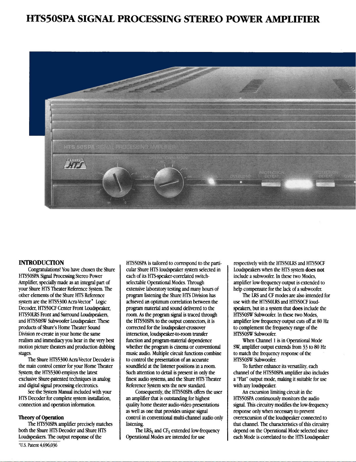
HTSSOSPA SIGNAL PROCESSING STEREO POWER AMPLIFIER
INTRODUCTION
Congratulations! You have chosen the Shure
HTSSOSPA Signal Processing Stereo Power
Amplitier, specially made
your Shure
other elements of the Shure
system are the
Decoder, HTSSOCF Center Front Loudspeaker,
HTSSOLRS Front and Surround Loudspeakers,
and
products of
Division re-create in your home the same
realism and
motion picture theaters and production dubbing
stages.
the
System; the
exclusive Shure-patented techniques in
and digital signal processing electronics.
HTS Decoder for complete system installation,
connection and operation information.
Theory
both the Shure HTS Decoder and Shure
Loudspeakers. The output response of the
'U.S.
HTS Theater Reference System. The
HTS5300 Am-Vector ' wc
HTSSOW Subwoofer Loudspeaker. These
Shure's Home Theater Sound
immediacy
The Shure
main
See the System Manual included with your
HTS5300 Am-Vector Decoder is
control center for your Home Theater
HTS5300 employs the latest
of Operation
The HTSSOSPA amplifier precisely matches
Patent
4,696,036
as
an integral part of
HTS Reference
you hear in the very best
analog
HTS
HTSSOSPA
cular Shure
each of its
selectable Operational Modes. Through
extensive laboratory testing and many
program listening the Shure
achieved
program material and sound delivered to the
room.
the HTSSOSPA to the output connectors, it
corrected for the loudspeakernossover
interaction, loudspeaker-to-room transfer
function and program-material dependence
whether the
music audio. Multiple circuit functions
to control the pr-ration of an accurate
soundfield at the listener positions in a room.
Such attention to detail
Enest audio systems, and the Shure HTS Theater
Reference System sets the new standard.
an amplifier that
quality home theater audio-video presentations
as
control in conventional multi-channel audio only
listening.
Operational Modes are intended for use
is
tailored to correspond to the parti-
HTS loudspeaker system selected in
HTSspeaker-correlated switch-
hours of
HTS Division has
an
optimum correlation between the
As
the program signal
prwm
Consequently, the HTSSOSPA offers the user
is
outstanding for highest
well
as
one that provides unique signal
The
LRSx
and CFx extended low-frequency
is
traced through
is
cinema or conventional
combine
is
present in only the
is
respectively with the
Loudspeakers when the
include a subwoofer.
amplifier low-frequency output
help compensate for the lack of a subwoofer.
The LRS and CF modes are
use with the
speakers, but in a system that
HTSSOW Subwoofer. In these two Modes,
amplifier low frequency output cuts off at 80
to complement the frequency range of the
HTSSOW Subwoofer.
When Channel
SW,
amplifier output extends from 33 to
to match the frequency response of the
HTSSOW Subwoofer.
To further enhance its versatility, each
channel of the
a "Flat" output mode,
with any loudspeaker.
An
excursion luniting circuit in the
HTSSOSPA continuously monitors the audio
signal.
This
circuitry modifies the low-frequency
response only
overexcursion of the loudspeaker connected to
that channel. The characteristics of
depend on the Operational Mode selected since
each Mode is correlated to the
HTSSOLRS and HTSSOCF
HTS system
In
these two Modes,
HTSSOLRS and HTSSOCF loud-
1
is in Operational Mode
HTSSOSPA amplifier
makmg
when
necessary to prevent
does
not
is
extended to
also
intended for
does
include the
80
also
includes
it suitable for
this
circuiy
HTS Loudspeaker
Hz
Hz
use
Page 3
AmA
CAUTION.
RISK OF ELECTRIC SHOCK
TO REOUCE
THE
RISK
OF
DO NOT REMOVE COVER
NO USER SERVICEABLE PARTS
REFER SERVICING TO OUALFIED SERVICE PERSONNEL
The llghtnrng flash w~th
arrowhead symbol, wlthln an
equilateral
tended to alert the user to
the presence of
"dangerous voltage" wlthtn
the product's enclosure that
may be of
tude to constitute a risk of
electrlc shock to persons
The exclamation point
within an equilateral trangle
is intended to alert the user
to the presence of important
operating and maintenance
(servicing) instructions in
the literature accompanying
the appliance.
ELECTRIC SHOCK
INSIDE
triangle,
un~nsulated
sufflcrent magnt-
IS
rn-
attached at the output terminals.
In
addition, the amplifier features a clipping
cud.
This
protection
distortion to the signal,
clipping" circuits.
the amplifier only when necessary to
term hard clipping.
circuit does not add
as
do ordmry "soft
Instead,
it reduces the
'lhis
circuit
can
gain
avoid long
be
of
selectively disabled by pressing the Protection
Defeat switch for
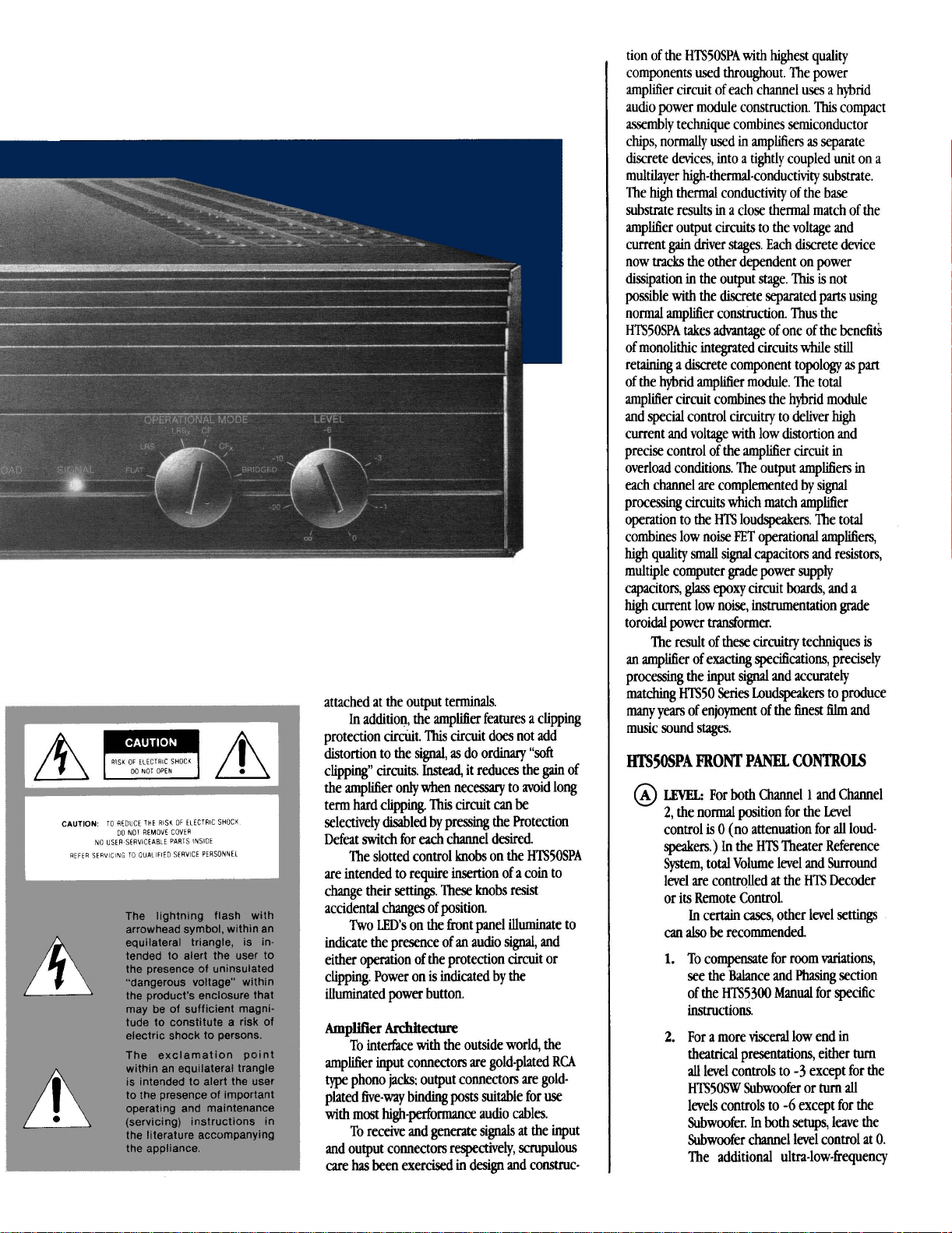
The slotted control
each
channel desired.
knobs on the HTS5OSPA
are intended to require insertion of a coin to
change their
settings. These knobs resist
accidental changes of position.
Two
LED'S
on the front panel illuminate to
indicate the presence of an audio signal, and
either operation of the protection circuit or
clipping. Power on
is
indicated by the
illuminated power button.
Amplifier
Architectme
To interface with the outside world, the
amplifier input connectors are gold-plated
type
phono
@;
output connectors are goldplated five-way bin@
with most
high-performance
posts
suitable for use
audio cables.
To receive and generate signals at the
RCA
input
and output connectors respectively, scrupulous
care
has
been exercised
in
design and construc-
tion of the
HTS5OSPA with highest quality
components used throughout. The power
amplifier circuit of each channel uses a hybrid
audio power module construction.
assembly
techque combines semiconductor
chips, normally used in amplifiers
dwrete devices, into a tightly coupled unit on
This
as
separate
compact
a
multilayer high-thermal-conductivity substrate.
The
high
thermal conductivity of the base
substrate results in a close thermal match of the
amplifier output circuits to the voltage and
gain
current
driver stages. Each discrete device
now tracks the other dependent on power
dissipation in the output stage.
possible
with
the discrete separated parts using
normal amplifier construction.
This
is
Thus
the
not
HTSSOSPA takes advantage of one of the benefi&
of monolithic integrated circuits while still
retaining a discrete component topology
as
part
of the hybrid amplifier module. The total
amplifier circuit combines the hybrid module
and special control circuitry to deliver high
current and voltage with low distortion and
precise control of the amplifier circuit in
overload conditions. The output amplifiers in
each channel are complemented by signal
processing circuits which match amplifier
operation to the HTS loudspeakers. The total
combines low noise
high
quality small signal capacitors and resistors,
FET operational amplifiers,
multiple computer grade power supply
capacitors,
high
glass
epoxy
circuit
boards,
and a
current low noise, instrumentation grade
toroidal power transformer.
The result of these circuitry techniques
an
amplifier of exacting specifications, precisely
is
processing the input signal and accurately
matching
many years of enjoyment of the
HTS5O Series Loudspeakers to produce
finest
film
and
music sound stages.
HTSSOSPA
@
FRONT
LWEL:
2,
the normal position for the Level
control
speakers.)
PANEL
For
both
is
0 (no attenuation for
In
the HTS Theater Reference
CONTROLS
Channel 1 and Channel
all
loud-
System, total Volume level and Surround
level are controlled at the HTS Decoder
or its Remote Control.
In
certain
cases,
other level settings
can
also
be
recommended
1.
To compensate for room variations,
see the Balance and Phasing section
HTS5300 Manual for specific
of the
instructions.
2.
For a more visceral low end in
theatrical presentations, either
all
level controls to -3 except for the
HTSSOSW Subwoofer or
levels controls to
Subwoofer.
-6
except for the
In
both setups, leave the
turn
turn
all
Subwoofer channel level conml at
The additional ultra-lowfrequency
0.
Page 4

emphasis in either alternate level
setting can provide exceptional
excitement and even greater enjoyment in home theater sound.
These slotted control knobs are
intended to require insertion of a coin to
change their settings; they resist
accidental changes of position.
@
OPERATIONAL MODE:
Mode switches select the signal processing characteristics of each amplifier
channel independently to complement
the response characteristics and excursion limits of the HTS Loudspeakers:
HTSSOCF Center Front, HTSSOLRS Front
Left,
Right and Surround, or HTS5OW
Subwoofer (selectable in Channel
only). These slotted control knobs are
also
intended to require insertion of a
coin to change their settings; they resist
accidental changes of position.
An
excursion limiting circuit
continuously monitors the audio signal,
and modifies the low-frequency response
only when necessary to prevent overexcursion of the particular HTS
loudspeaker connected to that channel.
The characteristics of this
depend on the Operational Mode
selected. This limiter circuit is always
active for loudspeaker protection.
There are two possible Operational Modes
for the CF and
according to whether or not a subwoofer is used
in the Home Theater Sound System. When the
selector is in the CF or
amplifier low frequency output cuts off at 80
to match the HTS5OSW Subwoofer response;
these Operational Modes should
when the
HTSSOW subwoofer.
When the system does not include the subwoofer, the selector should be in the
LRS,
Mode. In these Modes, the amplifier low frequency output extends down to 60 Hz: the extended low-frequency output signal is intended
to help compensate for the lack of a subwoofer.
@CHANNEL1
LRS Loudspeakers, selected
HTS system does include the
FLAT:
Output has no signal processing in
the signal path other than the defeatable
clipping protection circuit. In Flat Mode
HTSSOSPA is suitable for
the
loudspeaker.
LRS:
Output is tailored to match the
HTS50LRS Loudspeaker with lowfrequency cutoff at 80
system that
LRSx:
Output matches HTS5OLRS Loud.
speaker with low-frequency extension
down to
does not include a
The Operational
circuitry
LRS position, the
Hz
does
include a subwoofer.
60
Hz
for use in a system that
subwoofer.
1
be
for use in a
selected
CFx or
use
with any
Hz
CF:
Output matches HTSOCF
I~udspeaker with low-frequency cutoff at
80 Hz for
include a subwoofet
CFx:
Loudspeaker with low-frequency exten-
sion down to 55
that does not include a subwoofer.
SW:
Subwoofer with controlled low-frequency
boost and response from
This
@
cHANNEI.2
Identical to Channel 1 except the
extreme clockwise position in Channel
is Bridge instead of W. Explanation
follows.
BRIDGE:
at both Channel 1 and Channel 2 plus
ournuts (Channel 2 Input does not
functionahen Mode &lector is in
Bridge.) Use the Operational Mode
selector of Channel
use
in a system that
Output matches HTS5OCF
Hz
for use in a system
Output matches HTS5OW
Moak
is
available only on Channel
Input from Channel
1
does
33
to 80
set to any appro-
1
Hz.
2
appears
(+)
I.
IPERAT
IONAL MO
'cF
3
priate position to control equalization of
the output to match
or set to Flat for any other loudspeaker;
use the Channel
determine the Bridged output level. In
Bridged Mode, the protection circuitry
for both channels should have the same
status (Protection Defeat pushbuttons
both
out or
watts into 8 ohms from
to Bridge Connection instructions for
specific details on connecting loudspeakers for
@
PROTECTION DEW:
pushbutton switches for Channel 1 and
Channel 2 disengage the built-in
protection circuitry that prevents longterm hard clipping at the output. Under
ordmry circumstances, the
most
protection circuits should
(Protection Defeat switch out.)
POWER:
power on and off.
The pushbutton switch turns
HTSSO Loudspeakers
1
Level control to
both
in). Total output is 250
1
volt input. Refer
hs Operational Mode.
Individual
be
engaged
PROTECT101
MFEAT
Page 5

binding posts that
following methods
wire wrapped around the post, bare wire
inserted through the hole in the post,
spade lug around the post, pin connector
through the hole in the post, or banana
plug inserted in the jack These output
connectors will accommodate most
performance audio cables. (Gold ,080-
inch diameter pins soldered to the loudspeaker cables and inserted under the
binding post hex caps [fastened fingertight] are the most reliable connection.)
To maintain proper speaker polarity in
the completed HTS system, it is
extremely
amplifier output ted is connected
only to a plus speaker
(-)
minus
connected only to a minus speaker
terminal.
@
CHANNEL 1 OUTPUT:
and minus terminals are used in
normal two-channel operation to
drive an
HTSSOSW or any other loudspeaker.
Only the plus terminal of Channel
is used as the plus or high side
output connection to a loudspeaker
when the
BRIDGED MODE
will
accept any of the
of
connection: bare
high-
important that each plus
ted, and each
amplifier output terminal is
Both plus
HTSSOCF, HTSSOLRS,
HTSSOSPA is in the
'
.
(+)
1
INDICATORS
@
POPER;
Power switch illuminates to indicate
power is on.
@
SIGNAL:
signal is present in the channel.
@
OVERLOAD:
indicate limiting when the Protection
Defeat switch
ping when the Protection Defeat switch
is pushed
lo;dspeakers, the overload light
on occasionally for high-level dialogue or
music
@
~IWOR
the supplied Indicator Tabs into these
slots when the loudspeaker
to the amplifier. The tabs show the
speaker location
channel (LEFT,
Red light in the pushbutton
Green light illuminates when a
Red light illuminates to
is
out,
or to indicate clip-
in.
In normal
peaks.
TM
use
with HTS5O
0
SLOB:
is
correspondmg to each
RIGHT,
CENTER,
will
turn
snap
connected
SURROUND LEFT SURROUND RIGHT,
SUBWOOFER OR BRIDGED.)
If
speaker locations are reassigned,
remove the tabs by carefully prying one
comer out of the slot with a pointed
instrument. The tab
with the
scratch or damage the amplifier front
hish when removing the indicator tab.
hgertips. Take care not to
BACK
@
INPUT
CONNECTOss:
2
Channel
duty gold-plated phono (RCA
Use
BRIDGED
@
OUTPUT CONNECTORS
connectors are five-way gold-plated
input connectors are heavy-
only-&el
MODE
:swum=
-
-----
-----
-
-----
tllr-
-
-
---
can
then
PANEL
Chml 1 and
1
input
output
-
-
is selected.
All
be
removed
type)
when
output
-
jacks.
@
CIIANNEL 2 OUTPUT:
and minus terminals are used in
normal two-channel operation to
drive an
HTS5OSW or any other loudspeaker.
Only the plus terminal of Channel 2
is used as the minus or low side
output connection to a loudspeaker
when the
BRIDGED MODE
@
EXTERNAL
Blo fuse accessible from the rear panel is
user replaceable.
disconnect the power cord, and remove
the fuseholder and fuse by pressing
inward and rotating counterclockwise.
Replace the
same
rating.
time, do not replace it
Shure Service Department or other
qualified service
the problem.
'See
HTSSOCF, HTSSOLRS,
HTSSOSPA is in the
FUSE:
The lOA, 250 V Slo-
If
the fuse should blow,
fuse
only with one of the
type,
same amperage and voltage
If
the fuse should blow a second
personnel to correct
Bridged
Connection
Both
'
.
again.
Contact the
instructions.
plus
Page 6

BRIDGED
If
the amplifier is used in the Bridged MtKie, to
CONNECTION
prevent the risk of electric shock the following
instructions describe the only acceptable
method of connection (see illustration).
Voltages in the Bridged Connection ate
hazardous to
speaker connections with
nected. Refer
life.
Make
all
amplifier-to-
AC
power discon-
senicing to qualitied senice
~ewnnel.
Thread the speaker lead through the hole
1.
in the supplied connector cover plate.
Loosen the insulated red locking cap on
2.
the binding post, strip the end of the
speaker lead (approximately 19
in.]
),
and
insert
the stripped wire into
the hole in the
bindmg post. Twist the
mm [3/4
stripped wire around the post and tighten
the locking cap.
Attach the cover plate over the binding
post terminal and fasten it
with
the
supplied screws.
CONNECTION
DETAIL
NOTE:
To ensure correct Bridged Mode speaker
polarity, connect the plus
(+)
terminal of
Channel 1 only to the plus speaker terminal and
connect the plus terminal of Channel 2 only to
the minus
(
-
)
speaker terminal.
Frequency Response
20 Hz to 20 kHz + 0.5 dB
Power Output
100 watts
Input Impedance
100 kilohms
Recommended
4 ohms
Input Sensitivity
0 dBV (1.0 V)
Dynamic Range
Greater
Power Requirements
120 Vac f lo%, 60 Hz
CeMcations
Listed by Underwriters Laboratories Inc.
Overall Dimensions
102mmHx429mmWx356mmD(4x 16%~ 14in.)
Weight
12.3 kg (27 lb)
minimum
Minimum
(Full
than
100
SPECIFICATIONS
(Flat Mode
Power Output in Flat Mode')
dB
'
)
per channel into 8 ohms
Output
Load
Impedance
from
noise level to clipping (300
with
BRIDGED
less than 0.1
Hz
to 20 kHz)
CONNECTION
%
THD
'In other modes Frequency Response
HTS
Loudspeakers' Frequency Response
and
Sensitivity are tailored to complement the
and
Sensitivity
individual
Page 7

TYPICAL
SYSTEM ARRANGEMENT
TYPICAL
SYSTEM CONNECI'IONS
Page 8

SHURE
HTS
The Home Theater Sound Division
222 Hartrey Avenue
l
L
Evanston,
60202-3696
of
Shure Brothers Inc.
Copyr~aht 1983.
27A8165
(IA)
Shore
BI-others
Inc
Pr~nted In
U.S.A.
 Loading...