

Page 1
Center Front Speaker
System
Page 2
HTS5OCF CENTER FRONT SPEAKER SYSTEM
INTRODUCTION
The HTSSOCF Speaker is specifically
designed for use in the Center Front location
in a Shure HTS Theater Reference System.
This speaker is fully compatible in response
and power handling characteristics
Shure HTSSOSPA Signal Processing Amplifier.
In a high performance home theater
sound system, the loudspeaker used in the
center
front position is subject to the most
rigorous performance demands,
in regard to output capability The HTSSOCF
meets those demands. The complete HTS
amplifier-speaker system employs extended
dynamic range techniques, especially suiting
the
HTSSOCF to the demands
recorded cinema and music audio programs.
In addition, the HTSSOCF Speaker
performance has been carefully matched in
terms of frequency response to the
IITSSOLRS Front Left and Right Speakers to
provide
uniform response across the front
sound stage for precise imaging and
unparalleled fidelity.
with the
particularly
of
both
System Application Alternatives
When the HTSSOSPA Amplifier is in the
CF Operational Mode, the amplifier and
speaker cut off at 80
to the
HTSSOSW Subwoofer; when the
Amplifier is in the CF, (extended) Mode for
a system without a subwoofer, the lowfrequency response extends
In either Mode, the HTSSOSI'A reduces
system distortion by controlling the cone
excursion at low frequencies and very high
sound levels.
Hz for a perfect match
doun to 55
IIz.
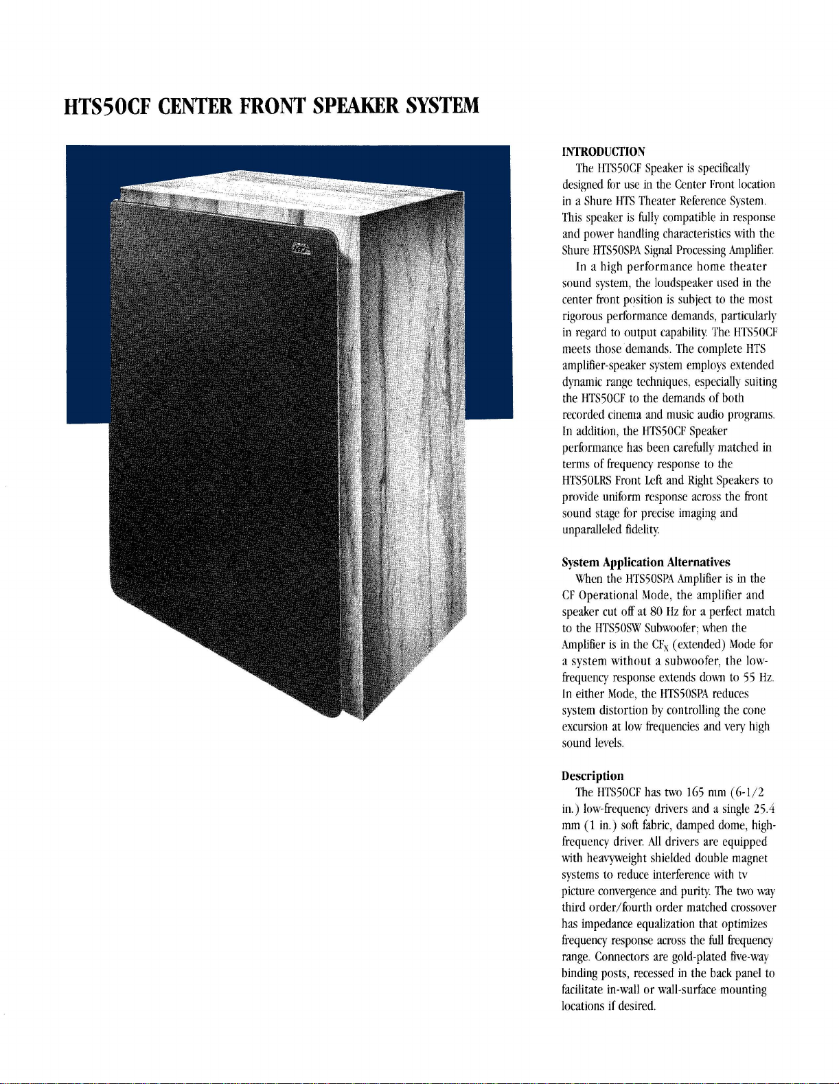
Description
The HTSSOCF has two 165 mm
in.) low-frequenq drivers and a single 25.4
mm
(1
in.) soft fabric, damped dome, highfrequency driver. All drivers are equipped
with heavyweight shielded double magnet
systems to reduce interference with
picture convergence and purity. The two way
order/fourth order matched crossover
third
has
impedance equalization that optimizes
frequency response across the full frequency
range. Connectors are gold-plated five-way
binding posts, recessed in the back panel to
facilitate in-wall or wall-surface mounting
locations if desired.
(6-112
tv
Page 3

PERFORMANCE
.
Wide frequency response range - 55 to
18,000 Hz used with the
extended Operational
Hz
18.000
.
At high sound levels, low-frequency driver
excursion control to reduce distortion when
used
in either CF or CF, Mode
-
Power handling compatible with IITSSOSPA
Signal I'rocessing Stereo Amplifier
.
Response carefully tailored to match
fITS50LRS Left and Right Front Speakers
for uniform
imaging with superlative fidelity
FEATURES
@
Low-Frequency Drivers
(Woofers)
.
Tw 165 mm (6-1/2 in.) low-frequency
drivers, each
magnetic structures arranged as a double
magnet system for magnetic shielding
against interference with
Location of the drivers in-line with a central
tweeter combines with the crossover for
a stable polar pattern
.
Curved polymer diaphragm with butyl
surround reduces diaphragm
enhances ideal piston motion
.
Iligh temperature copper wire on slotted
38.1 mm
which extends from the magnetic gap with
a flat spider suspension; all elements
combine to reduce distortion and assist at
more demanding program levels
"Soft-pad" stop on magnetic structure top
plate prevents damage in abnormal
diaphragm excursion situations
.
Cast aluminum low-frequency driver frame
precisely
structure and enhances driver thermal
radiation properties by conducting heat
from inside box
@
High-Frequency Driver
.
25.4
high frequency driver (tweeter) with 567
g (20
provides magnetic shielding
.
Diaphragm back damping material and
front center dome
annular acoustic-foam damping material,
result in controlled high-frequency
dispersion
in Operational Mode CF)
with the HTS50SPA f'o~ver Amplifier
hnt sound stage and precise
with 2 kg (4-1/2 Ib)
(
1 - 1/2 in.) diameter force-coil
mates diaphragm
('Rveeter)
mm
(1 in.) soft fabric, damped dome,
oz) double magnet system that
HTSSOSPA in
Mode CFx (80 to
hr
picture
influences and
to
magnetic
dillhtion ring, including
.
Fluid cooling in magnetic gap ensures
stable operation at high program levels
.
Cast aluminum front plate provides
distinctive appearance, rugged precision fit,
and added heat radiation properties
@
.
-
.
@
Crossover, @ Connectors
and @Fuse
.
Tho
way third order/fourth order matched resonances
crossovers with impedance equalization on
drivers improve power handling across the
full frequency range
.
High quality glass-epoxy circuit board with
precision nonpolar and mylar capacitors
and large
wire, ferrite core, inductor coils
Construction
Handsome walnut veneer finish, attractive
with or without front grille
Finished octagonal front edge of driver
frames provides special designer
appeasance
25.4 mm ( 1 in.) thick, dense particle board
for all cabinet panels with front-to-back
bracing that greatly reduces panel
Multipoint mounting screws lock
frequency driver frames to cabinet and
minimize motion other than diaphragm
Kumerically-milled recessed-front-baffle
driver mounting decreases baffle wave
difkaction at higher frequencies
low-
Page 4

.
I~~tc~rriail liherglass filler damps st;indiiig
~\;~\os and ol)tiniizcs system response
.
'l'ranstluccrs offset
11;tWc
a111t1
on
the front baffle with
grille-l'ra~ne-1110~1ntcd
;tcoustic
foam llatls to rctlucc tweeter sou~~ti \law
tiiffractio~~ at box edge and from \vooft:r
cone ca\'ities
.
Kccessctl hack panel terri~ir~als and fuse
f
au11t;itc
.. .
mounting illside, or flush a~ainst,
u-all if tccll~ired
-
(irillc constructetl
of
low-difiaction "opcn
sp;tcc" molticd plastic frame covered by
;u.oustically transparent grille cloth materi;d
.
1)istinctivc grille appumr1w incorporates
offset hafile-board-mounted locator pins
that allow similar visu;il display \vllen ho\
is rot:itetl ')0° ant1 grillr: is rcmovccl ant1
turncd 1 SO0 (scc instructions helo\+)
CONKECI'IONS
'I'he most relia1)lr colrnections arc niacie
aith gold .OSO-inch diameter pins soldered
to
the loudspcaker cahlcs and insertctl
ilrider the bi~~tling post Iics c;lps, hstcrictl
finger-tight hut veq snug.
'li)
mairrtain proper polarity in the
colnl)leted 1I'I'S S!ste~li, it is
imlx)rtant that a plus
is
connected only to a plus speaker tcrt~iinal,
ant1 a 111inus
(
(+)
-
)
ariljtlificr tcrniinal is
estrelr~ely
amplifier terminal
conrlectrtl only to a minus spcakcr tcrniinal.
LOCATIN(; THE SPEAKER
'l'hc lI'I'S50(:F
is
i~itentictl for usr in
a
vcrtical configuration in the center front
position. If space docs riot
position, ttic boa can
riglit \\ith rnininlal ch;inge
dispersion.
(See instructions belo\$- for
per~liit the ~.ertic;ti
brt
rotateti 90° to thc
in
responsc and
ni:iintaining clesig~i integrity.)
Locate the center speaker as close as
possible to the
centerline of the tv scrcen.
Ikst i~riagi~ig is ohtaincd wit11 all front
sl~eakers (1,eft. Kight.
approintey the
floor. With a rear projection
rest
the IITSiOCF directly o~i
of
the cahirret: \tith a front projection h rlitli
;inti
(;cntrr) at
same
height aljove the
t\:
)ou can often
thr
top surfaicc
sel':uatr2 projector arid screen. thrre is
~lsually room helow the screen: otlier\\isc~
ii
shelf above the screeti is likely the best
location.
(:I shelf slioultl bc capable
of
supporting a static loatl of 6- kg [ltS lh].
t
times the \wight of the spr;ikt:r. ) In the
cabinet
top
position, the loudspeaker should
be
located as close as possible to the korit
cabinet edge ( just abo\c the screen) to
retluce ~~ntlcsirablc iuve rctlcctiorrs that
dt~grade the sound quality.
REINSTAI,I,ING GRILLE FOR
HORIZON'M. SPEAKER
To
maintain tlcsign intcgrit) wlitl~i the
spraiher is horizontal, rotate the loutlspeaker
grille by lSOO, and reinsert it into the baffle
mounting
holcs.
'li)
then reassign the Shure
IITS logo, loosen its push-on-type fastener
on
the back surfiice of the grille, rotate the
logo to the pn)per orientation. and retighten
the fiistener.
SPECIFICATIONS
'&pe
Frecluenq Response
i5
flz
to IS Mlz (with II'I'SiOSI!Z I'ofier
.2niplificr in
to
IS k117 (with I1'I'SSOSI!I I'o!ver
lImpli&,r in
(:I:,
e\tentletl Mode): SO flz
(3:
Mode)
System Sensitivity
88
dl)
S1)L at 1
111
on
axis \\it11 2.83 \ac
\\idel):ind pi~ik noisc input sign:iI at
lITSiOSI?\
(IITS5OSI)~i in
I)o\\cr
(11:
:\n~plifir~r
or
CF,
terminals
Motlc)
Power Hatidlitig
LOO
wtts pc;lk m;~\imtt~ii for \\-itl(~
tlpamic I.;rngc program niatcrial: nomirial
:ini~)lificr l)o\\el: 100
\+;uts
into
an
8 oh111
load
Transducers
1.0~-Freque11cy:
'lko 165 Inn1
(7i)tal ~itiinting ;irc;i:
(6-
I/? in.) \voofers
S,,
=
280
CIII')
Magnet structure (each tr;uisrlucer):
2 kg (.t-112
primary magnet
11))
\\it11
~atl
.tit
255
g
(
10 o~j
g
(0
OL)
sliicltf magnet
Iliglr-l:rcqucncy:
One 25.4
(Tot;il radi;rting 3rc;r: St,
Xlagnct
50- g (20 ozj ~vitll 255 g
priniar) niagnct ;uid 128 g
rlirll
structure:
(
I
in.)
>oft
clo~iic t\\clettar
=
i.
1
(9
o~)
(.I-I,'.!
c.rni)
sliitld magnet
Crossovers
'ftiirtl orderifourth order 1);~ssivc
crossovers nrth driver inil~c~tl:inct,
equa1iz:ltion
Protection
i
'imp Fast I<lo\t luje (hig11 irecjueric!
clr~~er only
)
Cabinet
25 4 mm ( l
111
)
p,irticlc ho,~rtf \\1t11
\\alnut \cncer
Dimensiorls
i08 mm 11
(
20 \ 1 i 1 '2 \ 8%
iti
Irinl
Ill
\\
j
\
2 I0 llrni
Net Weight
108 kg
(i'
Ih)
07)
I)
Page 5

TYPICAL
SYSTEM ARRANGEMENT
TYPICAL
SYSTEM CONNECI'IONS
Page 6

Copyright 1988, Shure Brothers
27A8183 (HF)
Inc.
Printed
in
U.S.A.
 Loading...