

Page 1
Price
$7.50
HOME
THEATER
SOUND
HTS5000
SURROUND
AUDIO
PROCESSOR
SERVICE
INFORMATION
MODELS: HTS5000, HTS5000E, HTS5000J
Home
Theater
Sound
Division
SHURE
BROTHERS INCORPORATED
222
Hartrey
Avenue
Evanston,
Illinois
60202-3696
Copyright
1W.
Shurm
Bmlhn
Inc
nrsra
(GO
UlO
Prlnfed
In
U.S.A.
Palent PIndlnp
Page 2
DESCRIPTION
-
OUTPUTS
TAPE
1
--m
-tg
0
0 0
,
&-go
-
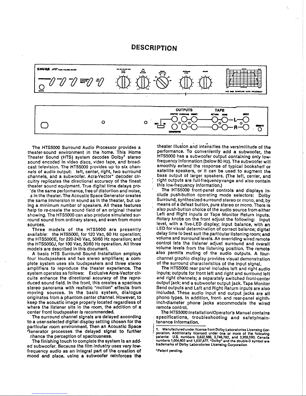
The HTSW Surround Audio Processor provides a
theater-sound environment in the home. This Home
Theater Sound (HTS) system decodes Dolby1 stereo
sound encoded
In video discs, video tape, and broad-
cast television. The
HTS5000 provides up to six chan-
nels of audio output: left, center, right, two surround
channels, and a subwoofer. Acra-Vector* decoder
clrcuitry replicates the directional accuracy of the finest
theater sound equipment. True digital time delays pro-
'de the same performance, free of distortion and noise.
s
in the theater. The Acoustic Space Generator creates
the same Immersion in sound as
In the theater, but us-
ing a minimum number of speakers. All these features
help to re-create the sound field of an original theater
showing. The
HTS5000 can also produce simulated surround sound from ordinary stereo, and even from mono
sources.
Three models of the
HTS5000 are presently
available:
the
HTS5000, for 120 Vac,
60
Hz operation;
the
HTS5000E, for 220.240 Vac, 50160 Hz operation; and
the
HTS5000J, for
100
Vac, 50160
Hz
operation.
All
three
models are described
In this document.
A
basic HTS Surround Sound Installation employs
four loudspeakers and two stereo amplifiers; a complete system uses
six loudspeakers and three stereo
amplifiers to reproduce the theater experience. The
system operates as follows: Exclusive Acra-Vector
clrcuits enhance the directional accuracy of the reproduced sound field.
In the front, this creates a spaclous
stereo panorama with realistic "motion" effects from
moving sources. In the basic system, dialogue
originates from a phantom center channel. However, to
keep the acoustic image properly located regardless of
where the listener sits in the room, the addition of a
center front loudspeaker is recommended.
The surround channel signals are delayed according
to a user-selected digital display setting chosen for the
particular room envlronrnent. Then an Acoustic Space
Generator processes the delayed
slgnal to further
nhance the perception of spaciousness.
The
finishing touch to complete the system is an add-
ed subwoofer. Because the film industry uses very
low-
frequency audio as an Integral part of the creation
of
mood and place. uslna a subwoofer reinforces the
theater illusion and
lrrt~nslfies the versimilitude of the
performance. To conveniently add a subwoofer, the
HTS5000 has a subwoofer output containing only lowfrequency information (below 80 Hz). The subwoofer will
smoothly extend the response of typical bookshelf or
satellite speakers, or
It can be used to augment the
bass output of larger speakers.
(The left, center, and
'
right outputs are full-frequency-range and also contain
'
this low-frequency informatlon.)
:
The HTS5000 front-panel controls and displays ln-
clude push-button operating mode selectors: Dolby
Surround, synthesized-surround stereo or mono, and, by
means of a defeat button, pure stereo or mono. There
Is
'
also push-button choke of the audio source from either
Left and Right inputs or Tape Monitor Return inputs.
Rotary knobs on the front adjust the following:
Input
level, with a five-LED display; input balance, with an
LED for visual determination of correct balance; digital
delay time to best suit the particular listening room; and
volume and surround levels. An overriding wired remote
control lets the listener adjust surround and overall
volume levels from the listening position. The remote
also permits muting of the audio outputs.
A
four-
channel graphic display provides visual demonstration
of the surround characteristics of the input signal.
The
HTS5000 rear panel includes left and right audio
inputs; outputs for front left and right and surround left
and right channels;
a
separately switched front-center
output jack; and a subwoofer output jack. Tape Monitor
Send outputs and Left and Right Return inputs are also
Included. These audio input and output jacks are all
phono types. In addition, front- and rear-panel
eighthInch-diameter phone jacks accommodate the wired
remote control.
The
HTS5000 lnstallationlOperator's Manual contalns
,
specifications, troubleshooting and safetylmaintenance Information.
7.
Manufactured under llcennr from Dolby Laboratories Llcenslnp
Cor
poratlon. Additionally licensed under one or more of the following
'
patents:
U.S.
numbers
3,632,886, 3,746,792,
and
3,959,590;
Canada
numbers
1,004,803
and
1,037,Bn.
'Dolby* and the double-D symbol
are
trademarks
of
Dolby Laboratories Llcenslnp Corporation
'Patent
pendln~.
Page 3
SERVICE
This section contains lnformatlon on replacement
parts, servlce access, fuse replacement, and complete
equipment checkout. If difficulties in
HTS5000 installation or operatlon are experienced, the Troubleshooting
Guide
In the installationlOperator's Manual should
be
consulted. If that information fails to correct the problem, the checkout procedure given here can
be
per-
formed.
Note that
circuitry
lnformatlon is only given where It can
be of use in field servlce; most internal adjustments
cannot be made and some circuit blocks cannot
be
ser-
viced without factory test equipment.
Voltages in this equipment are hazardous to life.
No user-serviceable parts inside. Refer all servicing to qualified servlce personnel.
Replacement Parts
Parts that are readily available through local electronic parts distributors are not shown on the accompanying Parts List. Their values are shown on the Circuit
Diagram. Commercial parts not readily available and
unique parts are shown on the Parts List and may be
m-dered directly from the factory.
'he commercial alternates shown on the Parts
Llst
are not necessarily equivalents, but may be used In the
event that direct factory replacements are not immediately available. To maintain the highest possible
performance and reliability, Shure fgctory replacement
parts should be used. When ordering replacement parts,
specify the Shure replacement part number,
descrip
tion, product model number, and serial number.
External
Parts
The following paris can be removed and replaced
without disassembling the
HTS5000:
Remote Control
(A13)
Rotary Knob
(MP1-Me)
Foot
(MFS-MP9)
.
All five front-panel knobs are either pull-off or setscrewretained types and are interchangeable. Setscrew-type
knobs must be unscrewed from
inside
the front panel
before removing the knobs.
Service Access
Disconnect the
HTS5000
from Its ac power source.
Remove two cover-securing screws from each side
panel. Slide the cover back toward the rear of the unit
and upward to remove.
Fuse Replacement
To replace the fuse or fuses in the
HTS5000, disconnect the line cord from the ac source and remove the top
cover as described above. Locate the defective fuse on
?
printed circult board adjacent to the power
-.ansformer, and replace with a fuse of ldentlcal slze
and value (see table). Note that all fuses are slow-blow
(time lag) types.
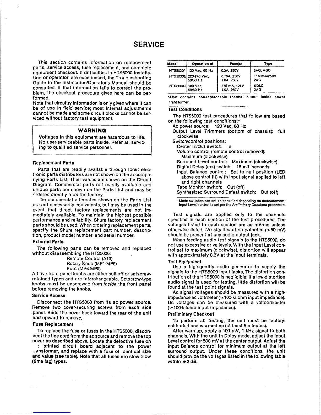
opt~tlon at
Fuw(r)
HTSSOOO*
120
Vac,
60
Hz
0.34
250V
3AG,
AGC
HTWE
2MZa0
Vac.
0.164
2WV
T160mAnWV
1
.OA,
250V
HTSSoOQl
100
Vac,
375
mA.
125V
50m0
HZ
1.04
2SV
'Also conlalns non-replaceable thermal cutout Inside power
trmsfomr.
--
T%
Conditions
The
HTS5000 test procedures that follow are based
on the following test conditions:'
Ac power source:
120 Vac,
60
Hz
Output Level Trimmers (bottom of chassis): full
clockwise
SwitcNcontroi posltions:
Center
Inlout switch: In
Volume control (remote control removed):
Maximum (clockwise)
Surround Level control: Maximum (clockwise)
Digital Delay (ms) switch:
16
milliseconds
lnput Balance control: Set to null position (LED
above control lit) with input
slgnal applied to left
and right channels
Tape Monitor switch: Out
(off)
Synthesized Surround Defeat switch: Out (off)
'Mode swltches are set as
specified
depending on measurrmenr;
lnput Level control Is
set
par
the Preliminary
Checkout
procedure.
Test signals are applied only to the channels
specified in each section of the test procedures. The
voltages listed in each section are ac
mVrms unless
otherwise listed.
No
significant dc potential
(>50
mV)
should be present at any audio output jack.
When feeding audio test signals to the
HTS5000, do
not use excessive drive
levets. With the lnput Level con-
trol set to maximum (ctockwise), distortion
wlll
appear
with approximately
0.3V at the input terminals.
Test Equfpment
Use a high-quality audio generator to supply the
signals to the
HTS5000
input jacks. The distortion con-
tribution of the
HTS5000
is negligible; if a lowdistortion
audio signal is used for testing, little distortion
will
be
found at the test polnt signals.
Ac signal voltages should
be
measured with a hlghImpedance ac voltmeter (2100-kilohm input impedance).
Dc voltages can be measured with a voltohmmeter
(~100-kilohm input impedance).
Prellmlnary Checkout
To perform all testing, the unit must
be
factory-
calibrated and warmed up (at least 5 minutes).
After
warmup, apply a
100
mV, 1 kHz signal to both
channels. With the
unit in Dolby mode, adjust the lnput
Level control for
500
mV at the center output. Adjust the
lnput Balance control for
minimum output at the left
surround
output. Under these conditions, the unit
should provide the voltages listed in the following table
withln
&2
dB.
Page 4

Mode Switch: Dolby Surround
1
kHz,
100
rnV
Input
to:
--
<M
rn~ <ZO rn~
X)O
rn~
Center
Right
<5
rnV
380
rnV
en
Sunound
c20 rnv cX) rnV
cro
rnV
Ri~ht Surround
<a
mV
c20
rnV
c10mV
Mode Switch: Stereo
lJsHr,lol,mVkprlto:
Center
Right
<5
rnV
270
rnV
Lett Surround
XY)
rnV
533
rnV
el0
mV
533
mV
clO
rnv
Mode Switch: Mono
Before Preliminary Checkout In the mono mode, adjust
the Mono Enhance Adjust control (located on the
chassis bottom). With the unit In the mono mode and a
100
mV, 1 kHz signal applied to both channels, adjust
the Mono Enhance Adjust control for
300
mV at the left
output.
Output
1
kHr,
100
rnV
Input
lo
both chrnnols
Center
Right
I
eft Surrwnd
ht
Sunound
280
rnV
Subwoofer Output
Proper operation of the subwoofer output can
be
veri-
fied by measuring the following voltages.
If the above voltages are measured, the
HTS5000
is
operating correctly. If any voltages are outside the
specified limits, the following procedure
will aid In
isolating the major circuit block that is causing the pro-
blem. Any circuit block (visible on the printed circuit as
an outlined block of components), with the exception of
the Directional Enhancement
(A6),
Direction Sensing
(A7)
and Digital Delay (A12) Blocks, can be serviced
using conventional circuit troubleshooting techniques.
Mode Swltth
Mono
Dolby
Checkout Procedure (cover
removed)
Power Supply Block
(A 1 1)
1
kHz, 1W mV
lnpul
io
both channels
190
rnV
270
mV
lnpul Block
(A2)
Component mersud
(to
ground)
Cathode of dlode
Dl105
Anode of diode
Dl100
Cathode of diode
Dl110
Mode
switch:
Dolby.
Proper operation of the lnput
Block .is verified by the following test point TP2.A and
TP2B
voltages.
Msrrunnwnt
+
15
Vdc
-15
Vdc
+5
Vdc
Use extreme care when measuring voltages
near
the 120 Vac power supply fuses (Fl100, F1101.
F1102).
Directional Enhancement
(A6)
and Direction Sensing
(A7)
Blocks
Tost Pdnt
Proper operation of the Directional Enhancement and
Direction
Senslng-Blocks was verified in the Preliminary
Checkout procedure
In the Dolby mode.
IMPORTANT: If Incorrect voltages were obtained in
the Preliminary Checkout, the
unit must be returned to
Shure Brothers Service Department. The Directional
Enhancement
(A6) and Direction Sensing (A7) Blocks
are not field-serviceable.
Digital Delay Block
(A12)
Proper operation of the Dfgital Defay Block was
verified in the Preliminary Checkout procedure.
IMPOR.
TANT: If incorrect voltages were obtained in the
Preliminary Checkout, the unit must be returned to
Shure Brothers Service Department. The Digital Delay
(A12) Block is not fleld.serviceable.
Dolby Noise Reduction Block
(A3)
Proper operation of the Dolby Noise Reduction Block
is verified by the following voltages at Test Point
TP3A.
Mode switch: Dolby Surround
Input to: Left Channel
1
kH&
100
mV
impul to:
Output
Level Control and Remote Block
(A9, AID)
Proper operation of the Output Level Control and
Remote Blocks was verified in the Preliminary Checkout
procedure in all
mcdes.
LOR Chrnnel
TP2A
I
4W
rnv
TF2B
4W
rnv
Input Ftvqurncy
LOO
Hz
4
kHz
Remofe Control Voltage
The Volume
(R1016) and Surround Level (R1014) con-
trols can be checked
by
turning them both to their
minimum (counterclockwise) positions and measuring
the following voltages with the wired remote control
disconnected from the
HTS5000.
Test Point TPlOA
.
. . . . . .
. .
. . . . .
. . . . . . . . . . .
4
Vdc
Potentiometer
R1014 (ungrounded side)
.
. . . .
.
4
Vdc
Wired Remote Control
Unlt
~eslstance. readings made at the miniature stereo
phone plug of the
HTS5000
remote control unit will ln-
dicate proper operation.
Both Chrnnols
m
rnv
<a
rnv
Input hre1
100
mV
730
rnv
703
rnV
10
mV
m
rnv
35
mV
Mersuternont
Slctevs
lo
rlng
Sleeve to tlp
(Mula
on)
Sleeve lo tlp
(Mule
off)
SwltcWontrd
Mute
Surround Level
Surround lewl
Volume Level
Surround
Lsvel
Volume
hl
Surround Lml
Volume
Level
Volume Level
5.fflng
OnorOH
Mlnlmum
.
Maxlmurn
Mu-Mln
MaxMIn
Mu-Mln
Mu-Min
Mlnlmum
Maxlmum
Rbadlng
BW120
80012000
>25Q
No chmw
No cbnw
16OBl000
No chrnps
850200
cm
Page 5
PARTS
LIST
The following pages contain a replacement parts list
for the
HTS5000. Part numbers not shown on the parts
list (except for Directional Enhancement, Direction Sensing, and Digital Delay Block parts which are also not
listed) are readily available through local electronics
parts suppliers. In these Instances, the circuit diagram
shows only the reference designation and value of the
standard parts.
SERVICE
ILLUSTRATIONS
Following the parts llst are an HTS5000 block
diagram, and clrcult diagrams and printed circuit board
layouts, including the basic
HTS5000, HTS5000E, and
HTS5000J power supplies.
Note that circuit
Information on the non-fieldserviceable Directional Enhancement, Direction Sensing, and Digital Delay Blocks
(A6,
A7
and
A12)
is not in-
cluded.
Power Supply
(All)
parts shown on the circuit
diagram
with
a
A
are critical and must be re
placed
only
with identical parts as specified by
Shure Brothers.
Page 6

REPLACEMENT
PARTS
LIST
Reference
Deslgnatlon
A1 3
C202,CXH
C301,W05-W06
C303,d312
C309
C400-C407
CllOO,C1106,
CllfO
'
C1102,C1107,
C1111
D416D420
050005(33
D50a
0890
D912.D914
D1100-Dl110
FllW
FllOO
F1101
FllOl
J200
J201
J202
J9W,J1000
L1
MPI-MPS
MP6-MP9
QB00-QB01
R107,
R309
R211
Description
Remote Control Assembly
Capacitor, Electrolytic,
2ZrF, 6.3V
Capacitor,
Electrolytic,
1 pF. 50V
Capacitor,
Electrolytlc, 10 rF, 16V
Shura
Part
Number1
Commerklal Alternate
Shure
90A8248
Shure 86V628; Mallory TAC226KOlOP05
Shure 86S628; Cornell-Dubilier NLWl.50
Shure 86Y628; Cornell-Dubilier
Capacitor, Electrolytic,
220
pF, 25V
Capacitor, Electrolytic, 2.2
rF, 25V
Capacitor,
Electrolytic, 10 pF, 35V
Capacitor,
Electrolytic, 1000 pF,
35V
Light-Emlttinp Diode, Clear
Light-Emittlng Diode, Green
Light-Emitting Diode, Red
Llght-Emitting Diode, Yellow
Zener Diode,
5.6V
Diode, Silicon Rectifier, 100V, II2A
Fuse, SIO-Blo, 3AG, 0.34 250V
(HTS5000)
Fuse, Time Delay, 375
mA,
125V
(HTS5OW.l)
Fuse, Time
Lag,
0.16A, 250V
(HTS5000E)
Fuse, SIo.Blo, Pigtall, 2AG, 1 A,
250V
(HTSWE, HTS5000J)
Phono Jack, Dual
Phono Jack,
4-Posltion
Phono Jack, &Position
Phone Jack, Miniature, Stereo
Ferrlte Balun
Core
(HTS5000,
HTW)
Knob,
Front
Panel
Feet
Transistor, NPN
Potentiometer, Trim,
1Ok
Potentiometer, Dual, lOOk
NLWIO-16
Shure 86x629; Nichlcon 1 E220MP.A
Shure 86AB628; Mallory
TAC225K025P02
Shure 86AA628; Mallory CTL-
lNM050PlA
Shure
86J629;
Sprague 503DlWF050SJ
Shure &A841 1
Shure B6A8410
Shure 8668410
Shure 86C8410
Shure 86A8409; Motorola lN5232A
Shure 86A404; Motorola IN4002
Shure 805159; Littelfuse Ser. 313000
Shure
86A6059; San-0 SDLC
Shure
80D380; Schurter
034.3109
Shure 80AgD52; Llttelfuse Ser. 230001
Shure
95A8127
Shure 95A8128
Shure 95A8129
Shure 95A8130
Shure 80AB051
Shure
31AB010
Shure 66AB002
Shure 86A350; Motorola 2N5210
Shure
468084
Shure 46A8019
Page 7
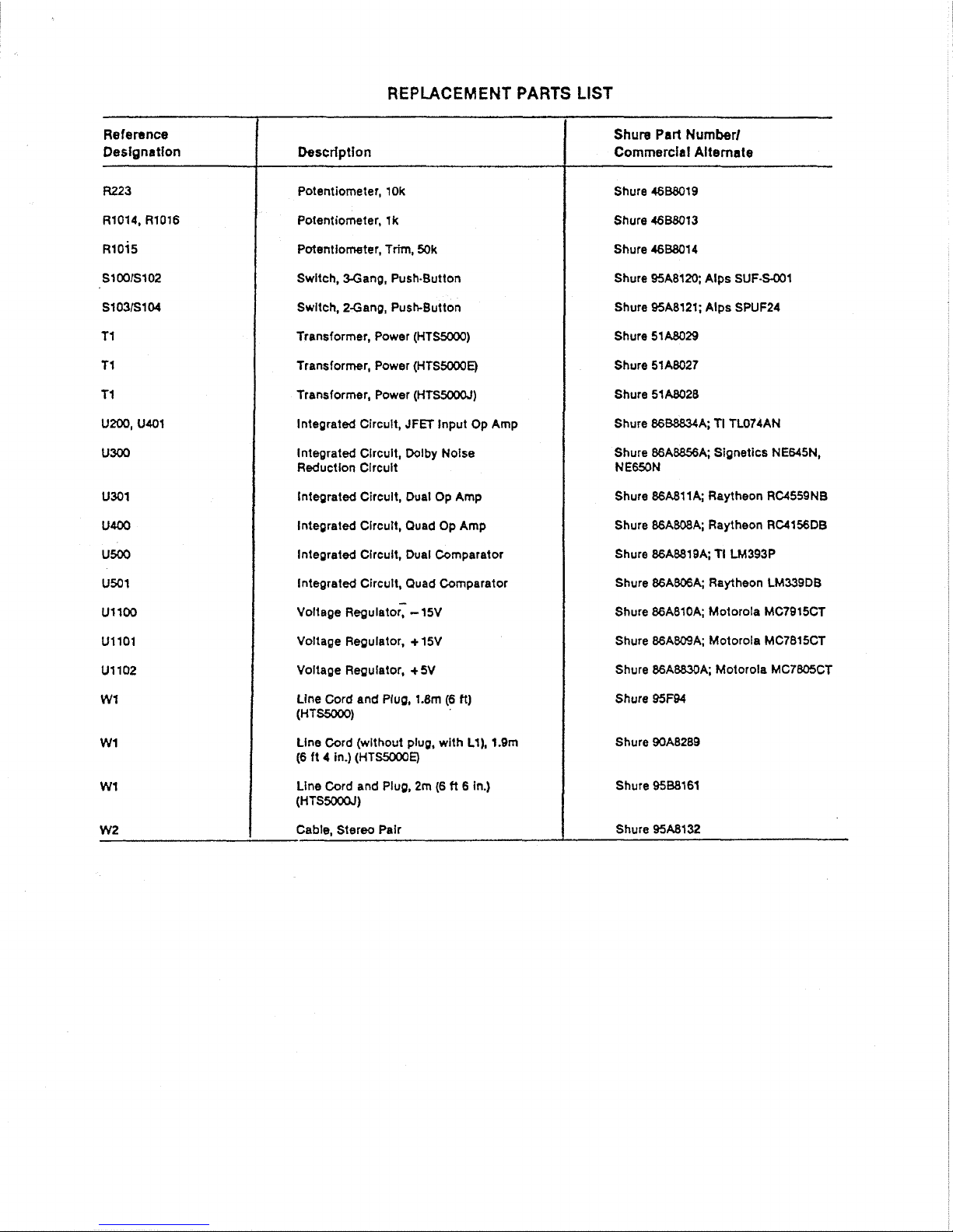
REPLACEMENT
PARTS
LIST
Reference
Designation
R223
R1014, R1016
~1015
S1001S102
S103/S104
TI
TI
TI
Urn,
U401
U300
U301
U400
USCK)
U501
UllOO
UllOl
U1102
W1
W1
W1
W2
Description
Potentiometer,
10k
Potentiometer, 1 k
Potentlometer, Trim, 50k
Swltch, 3Gang, Push-Button
Swltch, Z-Gang, PushButton
Transformer, Power (HTS5000)
Transformer, Power (HTS5000E)
Transformer, Power (HTS5000J)
Integrated Circult,
JFET
Input Op Amp
Integrated Clrcult, Dolby Nolse
Reduction
Circuit
Integrated
Circult, Dual
Op
Amp
lnteprated
Clrcult, Ouad Op Amp
Integrated Circuit, Dual Comparator
Integrated
Circult, Quad Comparator
Voltage
~e~ulato< - 15V
Voltage Regulator, + 15V
Voltage Regulator,
+SV
Line Cord and Plug, 1.8m
(6
ft)
(Hf
S5ow
Llne Cord (wlthout plug, with Ll),
1.9m
(6
ft
4
in.) (HTS5000E)
Line Cord and Plug, 2m
(6
ft
6
In.)
(HTSsoOar)
Cable, Stereo Pair
Shure
Part
Number1
Commercial
Alternate
Shure 4688019
Shure
46BB013
Shure 4688014
Shure 95A8120; Alps SUF-S001
Shure 95A8121; Alps SPUF24
Shure 51AB029
Shure 51AB027
Shure 51AB028
Shure 86-A; TI TL074AN
Shure 86A8856A; Sipnetics NE645N,
NE650N
Shure BGA811A; Raytheon RC4559NB
Shure 86ABOBA; Raytheon RC4156DB
Shure 86A881BA; TI
LM393P
Shure 86A806A; Raytheon LM339DB
Shure 86A810A; Motorola MC7915CT
Shure 86A809A; Motorola MC7815CT
Shure 86A8830A; Motorola MC7B05CT
Shure WFW
Shure 90A8289
Shure 95B8161
Shure 95A8132
Page 8
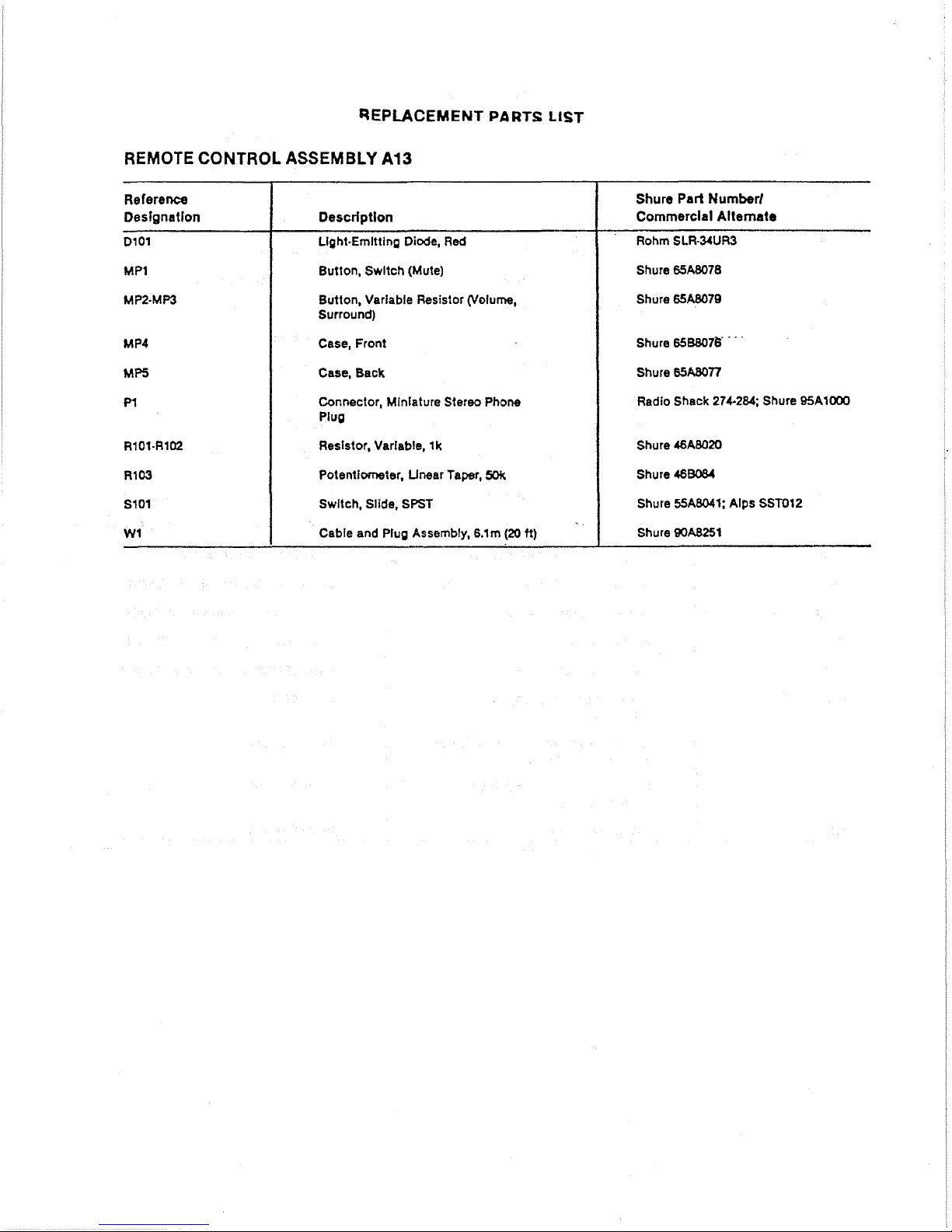
REPUCEMENT
PARTS
LIST
REMOTE CONTROL ASSEMBLY
A13
Shure
Part
Number1
Commercial
Allemate
Rohm SLR-34UR3
Shure
65A8078
Shore
65A8078
Shure
658807E
'
Shure
65-n
Radio Shack
274-284;
Shure 95A1000
Shure
46A8020
Shure
46B084
Shure 55AW1; Alps
SST012
Shure
@JAB251
Reference
Designation
Dl01
MP1
MP2-MP3
MP4
MP5
Pl
R101-RIM
R103
SlOl
W1
Description
Light-Emltting Diode,
Red
Button, Swltch (Mute)
Button, Variable Resistor (Volume,
Surround)
Case, Front
Case, Back
Connector, Miniature Stereo Phone
Plug
Resistor, Variable,
lk
Potentimeter, Unear Taper,
5Qk
Swltch, Slide, SPST
Cable and Plug Assembly,
6.1m
(20
ti)
Page 9

L
--
LEFT
R
-
RICH1
c
-
crxrrr
s
-
runnowno
-~oolc
www
--msGML8YIDUlYOOamm%MLTYIL*
------
%I.
L
C
n
11
MODEL HTS5000
SURROUND AUDIO PROCESSOR
BLOCK
DIAGRAM
Page 10

NOTES
TO
SERVICE
ILLUSTRATIONS
The notes below apply to the partial circuit diagrams
and printed
clrcult board layouts shown on the follow-
ing pages. As previously stated, information is
not
in-
cluded on the Directional Enhancement Block
(A@,
Direction Sensing Block (A7). and Digital Delay Block
(A12).
In addition, only partial information is given on
the Output Level Control
&
Remote Block (A9,
A10).
This
is done because the equlpment required for
troubleshooting, adjusting and repairing these circuits
is not available
outside Shure's factory.
Remember that
all
Internal adjustments are con-
sidered factory-serviceable only. Field repair should
be
limited to replacing known defective parts, repairing
defective connections, etc. Attempting to calibrate the
HTS5000
in
the field without proper equipment (including computer setup) can result in serious performance problems.
1.
All resistors are 114W,
5%
unless otherwise
specified.
2.
All capacitors in microfarads and
50
volts or more
unless otherwise specified. Electrolytic capacitors
shown in microfarads
X
volts.
3.
The following symbols denote:
PC
Board
A
Chassis
Ground
"
Ground
4.
The printed clrcult board is subdivided into sections
where the first two digits of the part number
describe Its "block."
A1
-
Mode Switching Block
A2
-
lnput Block
A3 - Dolby Noise Reduction Block
A4
-
Directional Display Block
A5
lnput Level Display Block
A6
-
Directional Enhancement Block
(drawings not supplied)
A7
Direction Sensing Block (drawings not supplied)
A8
-
lnput Balance Display Block
A9,10 - Output Level Control & Remote Block
(parfial drawings supplied)
All
-
Power Supply Block*
A12
-
Digital Delay Block (drawings not supplied)
A13
-
Remote Control Assembly
'Separate
drawings
provlded
for
the
HTSXK)O,
HTSWE
and
HTSXKXU.
5.
To eliminate risk
of
fire or electrical shock, all cornponents In the power supply indicated
wlthA
are critical components and must
be
replaced only with identical parts as specified by
Shure Brothers lnc.
Page 11

MODE
SWITCHING
BLOCK
A1
(snow
11
(SJ+OW
I#
I-----
gsmm
-------A
-1~.
POSITIOW~
-YOR)UL-
PD~I~ID*)
.
~a
oo~er
OURROUHD-
~OS~TIMO
Page 12

Page 13

INPUT
BLOCK
A2
Page 14

INPUT
BLOCK
A2
Page 15

DOLBY
NOISE
REDUCTION
BLOCK
A3
Page 16

DOLBY
NOISE
REDUCTION
BLOCK
A3
Page 17

DIRECTIONAL
DISPLAY
BLOCK
A4
Page 18

DIRECTIONAL
DISPLAY
BLOCK
A4
Page 19

INPUT
LEVEL
DISPLAY
BLOCK
A5
Page 20

INPUT LEVEL DISPLAY.BLOCK
A5
Page 21

INPUT
BALANCE DISPLAY
BLOCK
A8
Page 22

INPUT
BALANCE
DISPLAY
BLOCK
A8
Page 23

OUTPUT LEVEL CONTROL
&
REMOTE BLOCK A9,
A10
(PARTIAL DRAWINGS SUPPLIED)
Page 24

OUTPUT LEVEL
CONTROL
&
REMOTE
BLOCK
A9,
A10
(PARTIAL DRAWINGS
SUPPLIED)
Page 25

POWER
SUPPLY
BLOCK
All
(HTS5000)
TO
ELIllIHATE RISK OF FIRE
OR
ELECTRICAL
SHOCK,
ALL
COWONEHTS IN THE POWER SUPPLY
INDICATED
VITH
A
ARE
CRITICAL
COnPOHEHfS
AND
MUST
BE
REPLACED ONLY UITH lDEWTICM
PARTS AS SPECI~ICD BY SHURE BROTHERS INC.
Page 26

POWER
SUPPLY BLOCK
All
Page 27

POWER
SUPPLY
BLOCK
All
(HTS5000E)
Page 28

POWER
SUPt
,Y
BLOCK
All
(HTS5000J)
Tl
A
I
1
01 104
I
Dl 10s
U.
TO ELIMINATE RISK
OF
FIRE.OR ELECTRICAL
SHOCK* ALL COMPONENTS
IN
THE POWER
SUPPLY
INDICATED WITH ARE CRITICAL COMPONENTS
AND MUST
BE REPLACED
ONLY
WITH IDENTICAL
I
'RED
ELK
l
OOV
BLK/REO
A
I
4-
*ISV
+
REDIYEL
RED
D'
n
86A404
UI 101
86A
009
fL
JWL
PARTS AS SPECIFIED
BY
SHURE BROTHERS INC.
..
--
+
I
t
BLU/YEL
--
-----
1
I
/
i
86A404
86A404
z,'
+
C.
FllO2
I
A.
250V
El
/I
SLOW-BLOW
9
01 108 01
l
lo
4b--+-
n
PI 100
861404 B6A404
J
1
n
86A404
CllO4 CIIO3 ~1102
Ll
--C11OS
--.
33
--c1101
-.
33
i
I
I
"1
A
t
OOV
AC
Pe°
125~~~
50/60
Hz
36W
-
86A404
-----
........................
-
C1107
1000
X35V
C1102
I000
--
x3sv
"
Dl
103
U
..
86A404
DllOl
-CI
106
IOX35Y
+
--Cl I00
1
OX35Y
Jv
-
n
86A404
.01
SOOV
I
I
'
A
U.
a-
.01
SOOV
t~ll~~
86A
BIO
Dl 100
I'L
-
-1C)-15V
i
-
------
n
Page 29

Page 30

 Loading...