

LEGENDARY
pERFORM
AN
c
(j)
ETM
GLX-D
Wireless
System-
GLXD4 Receiver
fao!
©
2017 Shure Incorporated
27
A35795
Printed
in China
(Rev
c€&
.
1)
11111111111111111111111111111111111111111111111111
User Gu1de
Le GUide de I
Bed1enungsa
Ma
nu
Gu1a
Gu1d
Ge
bru1k
PyK
OBOll
CT
'U
I1
nl
e1
al
do Usuano
d
el
Usuano
a deii'Ut
en
ershandle1
BO
n
on
b
1isa
tu
30s
teur
ng
te
d1ng
ar
enA


Half-Rack Wireless Receiver
·-
-··
-·
------
IMPORTANT
1.
READ these instructions.
2.
KEEP these instructions.
3.
HEED
all
warnings.
4. FOLLOW all
5.
DO
6. CLEAN
7.
DO
ventilation
8.
DO
heat registers, stoves,
duce heat. Do not place any open
9.
DO
A
polarized plug has two
type
third prong are provided for your safety.
your
10. PROTECT
convenience
11.
ONLY USE
12.
USE only
facturer,
moving the cart/apparatus combination to avoid injury from tip-over.
Explanation
instructions.
NOT
use this apparatus near water.
ONLY with dry cloth.
NOT block any ventilation openings.
and
NOT install
NOT
defeat the safety purpose
plug
has two
outlet, consult an electrician
the power cord from being
receptacles,
attachments/accessories specified
with a cart, stand, tripod, bracket,
or
sold
of
Symbols
SAFETY
install
in accordance with the manufacturer's instructions.
near any heat sources such
or
other apparatus (including
blades
blades
and a third grounding prong. The wider
and the point where they exit from the apparatus.
with the apparatus. When a cart is used, use caution when
INSTRUCTIONS
Allow
flame
sources on the product.
of
the
polarized
with one wider than the other. A grounding
If
the provided
for
replacement
walked
---
sufficient distances for adequate
as
open
flames,
amplifiers)
or
grounding type
plug
of
the
obsolete outlet.
on
or
pinched, particularly
by
the manufacturer.
or
table
specified by the
...
·--
..
-
~
------~·-
radiators,
that pro-
plug.
blade
does not fit into
or the
at
manu-
··
·
·
~--
plugs,
13. UNPLUG this apparatus during
when unused for
14. REFER
quired when the apparatus has been
power
supply cord
jects have
rain
or
moisture, does not operate
15.
DO
NOT
put objects
16. The
MAINS plug
17. The airborne noise of the Apparatus does not exceed
18. Apparatus with
MAINS
socket
19. To reduce the risk of fire
pose this apparatus to rain or moisture.
20.
Do not attempt to modify this product. Doing so
sult
in
personal
21. Operate
long
all
servicing to qualified
or
fallen
expose the apparatus to dripping and
filled
this product within its specified operating temperature range.
plug
into the apparatus, the apparatus has been exposed to
with
liquids,
or an
CLASS I
outlet
with a protective earthing connection.
injury and/or product
lightning
storms
periods of time.
appliance coupler shall remain
•
service personnel.
is damaged,
construction
or
electric
damaged in any way, such as
normally, or has been dropped.
such as vases, on the apparatus.
shall
shock,
failure.
or
liquid
has been
splashing. DO NOT
be connected to a
do
not
ex-
could
Servicing is
spilled
or
readily operable.
70dB
(A).
re-
re-
ob-
Caution: risk
Lh
Caution: risk
&
Direct current
---
,--..,___.
Alternating current
On (Supply)
I
Equipment protected throughout
D
Stand-by
C)
Equipment
)?!
-
WARNING:
voltage
WARNING:
WARNING:
WARNING:
Voltages
is changed from the factory setting.
Battery packs
Danger of
This product contains a chemical
WARNING
•
Battery packs may
• Follow
•
instructions from manufacturer
Never put batteries in mouth.
Do
not short circuit; may cause burns
Do
not charge
Dispose of battery packs
should
in this equipment are hazardous to
explosion
&
explode
or
use battery packs with other than specified Shure products
of
electric
of
danger
not be disposed
shall
not
be
if incorrect battery
or
release
If swallowed,
properly.
shock
(See note.)
by
DOUBLE INSULATION
of
life.
exposed
to
excessive heat such
replaced. Operate only
known to the State
toxic
materials.
contact your physician or
or
catch fire
Check with
local
or
REINFORCED INSULATION
in the
normal
waste stream
No user-serviceable parts inside. Refer
as
sunshine, fire,
with AA batteries.
of
California
Risk of fire
vendor for proper disposal
or
to cause cancer and birth defects
burns. Do not open, crush, modify,
local
po
ison control
of used battery p
all
servicing to qualified service
or
the
like.
disassemble,
center
ac
ks
personnel.
Th
e safety certifications
or
other reproductive harm.
heat above
140° F
do
(60 °C},
not
apply when the operating
or
incinerate
Note:
•
This equipment is intended to be used in
EMC
conformance is based on the use of
Use this battery charger
increase the risk of fire
Changes or modifications not
Note:
Use only
with the
only
or
explosion.
included
with
expressly
power
professional
supplied and recommended
the
Shure charging
approved by Shure
supply
or
a
Shu
re-approved
audio applications.
modules
and battery
Incorporated could
equivalen
cable
types. The use of other
pa
cks for which it is designed. Use with other than the specified
void your authority to operate this equipment.
t.
cable
types may degrade EMC performance.
modules
and battery packs may
System
GLX-D Advanced Digital Wireless Systems combine Automatic Frequency Management technology with a rack mountable metal
world-renowned microphones, and
er
systems for increased channel count and improved
mount antennas
Digital Wireless sets the standard for ease of operation and digital audio
Overview
----
···
·'
closer
~
'
~-
.
.
..
..
unparalleled design and construction. New GLX-D Advanced Frequency Managers
to transmitters,' with directional reception for improved performance.
RF
reliability,
consolidating
clarity.
RF
to one pair of antennas. New antenna accessories
Available
in
a variety
(available separately) connect
of
bodypack and handheld configurations, GLX-D Advanced
receiver, rechargeable
help
multiple
improve reception by letting you
lithium-ion
GLXD4R receiv-
batteries,
Features
Exceptional digital audio
Operates in globally unlicensed 2.4 GHz spectrum
Optional
GLX-D Frequency Manager allows operation
New antenna accessories for remote mounting
Half-rack size and
clarity
metal chassis
of
up
and
improved reception
to
Furnished Accessories
Reverse
To reduce set-up time, the transmitter and receiver automatically
dio channel the first time they are powered on and never have to be
SMA Bulkhead
USB Cable,
0.6
m
Shure Lithium-ion
Adapters,
Type A to Micro-B
(2ft.)
Reverse
Rechargeable
lockwasher,
SMA
Cable UA802-RSMA
Power Supply
Battery
nut 95A32436
95A21651
PS43
SB902
link
11
systems
to form an au-
linked
again.
Rechargeable batteries
• Adjustable transmitter gain to optimize audio
Automatically moves away from interference without audio interruption
RF back-channel for remote control of transmitter functions
Automatic transmitter power-off to conserve battery
use
Optional
GLX-D Frequency Manager
Passive Directional Antenna 2.4 GHz
Reverse
ISM,
Wall Mount for
1/2 Wave Antenna, 45 deg. (2.4 GHz)
0.6
1.8 m
7.6 m
15.2
30.4
Reverse
Stand
Car
SMA Passive
DECT, 2.4 GHz)
m
(2ft.)
Reverse
(6ft.)
Reverse
(25ft
.) Reverse
m (50
ft.) Reverse
m
(100ft.)
SMA
Alone
Single Battery Charger
Battery Charger
deliver
cost efficiency and
Accessories
··~
., ....
-~---~~~~
~
-~·
.,
.~---~-~--~---~--~---~--~~~~~-----¥~~---
Antenna
PA805Z2-RSMA
SMA Cable
SMA Cable
SMA
SMA
Reverse
Bulkhead Adapters
Splitter (900
and UA8-2.4GHZ
Cable
Cable
SMA Cable
up
to 16 hours of runtime
signal
life
when transmitter is not in
MHz
UA846Z2-LC
PA805Z2-RSMA
UA221-RSMA
UA505-RSMA
UA8-2.4GHZ
UA802-RSMA
UA806-RSMA
UA825-RSMA
UA850-RSMA
UA81
95A32436
SBC10-902
SBC-CAR
00-RSMA
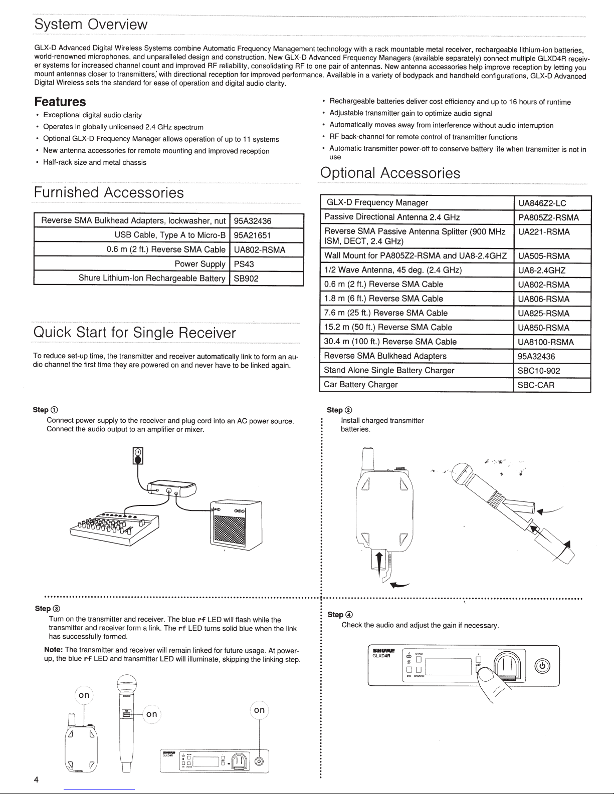
Step
CD
Connect power supply to the receiver and
Connect the audio output
to
an
amplifier
plug
cord into an AC power source.
or mixer.
.....................................................................................
Step
@
Turn on the transmitter and receiver. The
transmitter and receiver form a
has successfully formed.
Note:
The transmitter and receiver
up, the blue
rf
LED and transmitter LED will illuminate, skipping the
/
..
..
-
..
....
\
'
On
)
link.
,T.
on
will
The
remain
blue
rf
LED turns
linked
rf
LED will
flash while
solid blue
for future usage. At power-
when the
on ·
the
linking
link
step.
Step®
Install charged transmitter
batteries.
.
........................................................................................
Step@
Check the audio and adjust the gain if necessary.
:;\!
SIIUiU!
GLXD
4R
!7
'
®
n
=-
~
~~
u
4
c:=J
§
.
~
I
(@
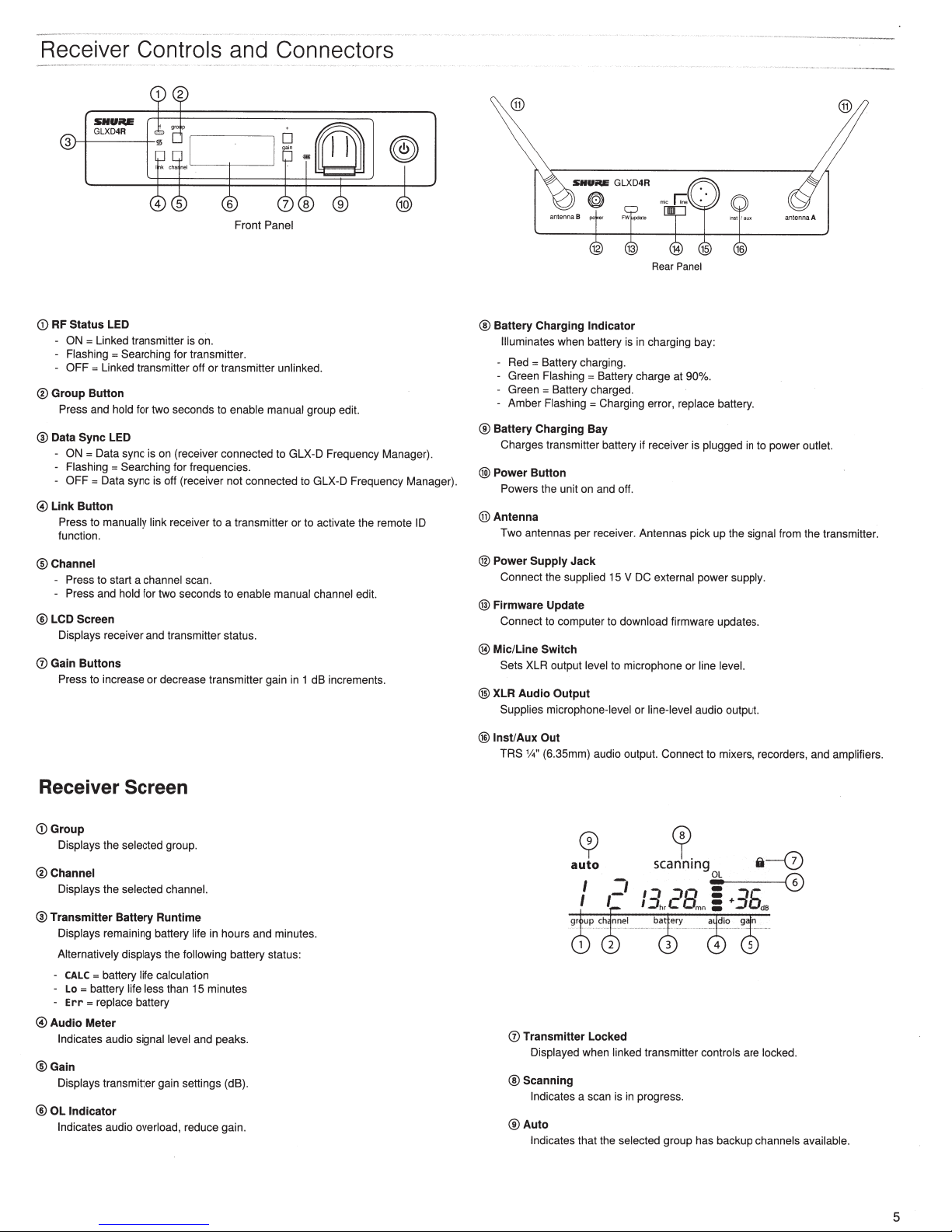
Receiver
CD
RF
Status
LED
ON
= Linked transmitter
Flashing
= Searching
OFF=
Linked transmitter off
®
Group Button
Press and
®
Data
OFF=
0
Link Button
Press to
function.
®Channel
- Press and
@LCD
Displays
0
Gain Buttons
Press
hold
Sync
LED
ON
= Data sync is
Flashing = Searching
Data sync is off (receiver
manually link
Press
to
start a
Screen
receiver
to
increase
Controls
for
for
two
seconds to
on
(receiver connected
for
receiver to a transmitter
channel
hold for
two
seconds to
and
transmitter status.
or
decrease
and
Front
is
on.
transmitter.
or
transmitter
enable
frequencies.
not
connected
scan.
enable manual channel
transmitter gain in 1
Connectors
Panel
unlinked.
manual
group edit.
to
GLX-D
Frequency Manager).
to
GLX-D Frequency Manager).
or
to
activate
the
edit.
dB
increments.
remote ID
@
SitU~
GLXD4R
ante
nn
aS
Rear
Panel
®
Battery Charging Indicator
Illuminates
Red=
Green
Green = Battery charged.
Amber
®
Battery Charging Bay
Charges transmitter battery if receiver is plugged
@
Power Button
Powers
®Antenna
Two
®
Power
Connect
@
Firmware Update
Connect to computer to download
@
Mic/Line
Sets
@
XLR Audio Output
Supplies microphone-level
when battery is in charging bay:
Battery charging.
Flashing
= Battery charge
Flashing
= Charging error,
the unit
on
and off.
antennas
XLR outp
Supply
the
Switch
per
receiver. Antennas
Jack
supplied
15
ut
level
to
V
DC
microphone
or
at
90%.
repl
pick
external
firmware updates.
or
line-level
ace
battery.
up
power
line level.
audio
output.
in
to
the signal
supply.
ant
power
from
enna
outlet.
the
A
transmitter.
Receiver
CD
Group
Displays
®Channel
Displays
®
Transmitter Battery Runtime
Displays
Alternatively displays
CALC
-
Lo
-
Err
0
Audio Meter
Indicates
®Gain
Displays
®
OL Indicator
Indicates
Screen
the
selected
the
selected channel.
remaining battery
the
= battery
=battery
=
life calculation
life less
replace
battery
audio
signal level
transmitter gain settings (dB).
audio
overload,
group
.
life
in
hours
and
following battery status:
than 15 minutes
and peaks.
reduce gain.
minutes.
@
lnst/Aux Out
TRS
%'' (6.35mm) audio output. Connect to mixers, recorders, and
cp
auto
cr
scanning
~
I
-:3
-:38
C
:
mn :
controls are
has
backup
0
Transmitter Locked
Displayed
@ Scanning
Indicates
®Auto
Indicates
when
a scan is in progress.
that the
linked
selected
I
::J
h,
transmitter
group
11----(D
+3L
Oda
locked.
channels
(6)
av
ailable.
amplifiers.
5
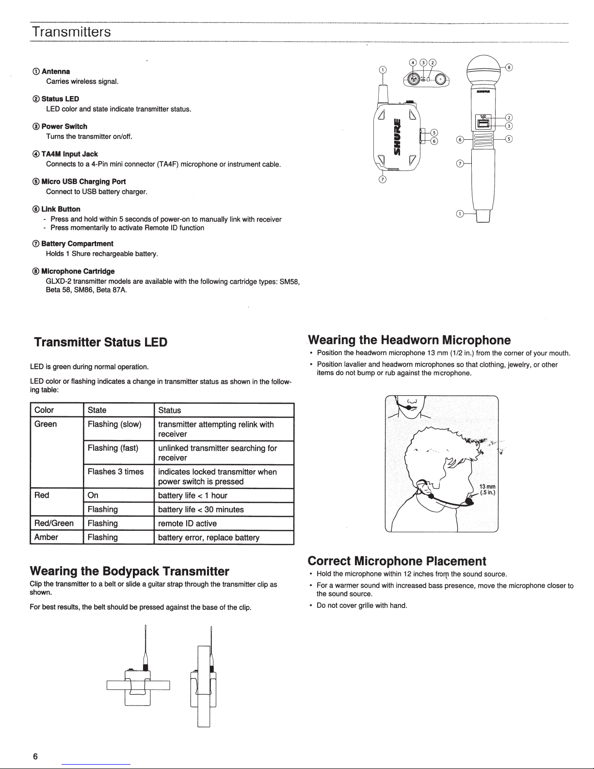
Transmitters
G)
Antenna
Carries
wireless signal.
®Status
®Power
@
®
@Unk
(i)
@
LED
LED
color
and state indicate transmitter status.
Switch
Turns the transmitter on/off.
TA4M
Input
Jack
Connects to a 4-Pin mini connector (TA4F) microphone
Micro
USB
Charging Port
Connect to
Press and
- Press
Battery Compartment
Holds
Microphone Cartridge
GLXD-2 transmitter models
Beta 58, SM86, Beta
USB
battery charger.
Button
hold
within 5 seconds of power-on
momentarily
1
Shure rechargeable
to activate Remote
battery.
are
87
available
A.
ID
with the
Transmitter Status LED
LED is green during
LED
color
ing table:
or
normal
operation.
flashing
indicates a change in transmitter status as shown in the
to
function
or
instrument
manually link
following
cartridge types: SM58,
cable.
with receiver
follow-
~
~
l
•
WI
[.7
Wearing the Headworn Microphone
Position the headworn microphone 13 mm (1/2 in.) from the corner of your mouth.
•
Position
lavalier
items
do
and headworn microphones so that
not bump or rub against the microphone.
clothing, jewelry,
or
other
Color
Green
State
Flashing (slow)
Status
transmitter attempting
receiver
Flashing
(fast)
unlinked
transmitter searching for
receiver
Flashes 3 times indicates
locked
transmitter when
power switch is pressed
Red
Red/Green
Amber Flashing
On
Flashing
battery
battery
Flashing remote
battery error, replace
life
life<
10
<
1 hour
30
active
minutes
Wearing the Bodypack Transmitter
Clip the transmitter to a
shown.
For best results,
belt
or
the belt should
slide
a guitar strap through the transmitter
be
pressed against the base
of
battery
the
relink
clip.
with
clip
as
Correct Microphone Placement
Hold
the microphone within 12 inches
For a warmer sound with increased bass presence, move the microphone
the sound source.
Do
not
cover
grille
with hand.
fro~
the sound source.
closer
to
6
 Loading...