

Page 1

Shure Incorporated
222 Hartrey Avenue
Evanston IL 60202-3696 U.S.A.
Model FP410 User Guide
FP410 PORTABLE AUTOMATIC MIXER
The Shure Model FP410 is an automatic microphone mixer
designed for usein a wide variety of multi-microphone speech
pickup applications. Shure IntelliMix delivers flawless automatic mixing by combining three unique functions:
Noise--Adaptive Threshold,
MaxBus, and
Last Mic Lock --On.
Noise--Adaptive Threshold distinguishes between constant
background noise (such as air conditioning) and rapidly
changing sound (such as speech).This function continuously
adjusts the activation threshold so that only speech levels
louder than the background sound will activate an FP410
channel.
MaxBus eliminates the poor audio quality that results when
a talker is picked up by more than one microphone. It does this
by controlling the number of microphones that may activate for
a single sound source. With MaxBus, one talker will activate
only one FP410 channel, even if multiple microphones are
“hearing” that talker.
Last Mic Lock--On maintains a seamless audio mix by keeping the most recently activated microphone open until a newly
activated microphone takes its place. Without Last Mic Lock-On, a long pause in conversation may allow all microphones to
turn off, and it may sound as if the audio signal has been lost.
Last Mic Lock--On ensures that background ambience will always be present.
Multiple miking situations—with a number of talkers participating—have always presented problems for the audio techni cian. If too few mics are used, the coverage of each talker may
vary, with one talker (nearest the mic) being louder and clearer
than the next. Talkers farthest from the mics will sound
“echoey” and reverberant, as very little of the direct sound from
their mouths reaches the microphones. If too many mics are
used, there’s more background noise and reverberation pickup, as well as less gain before feedback if a sound reinforcement (PA) system is used.
It’s somewhat like having multiple video cameras all focused on the same subject. If these camera signal are combined, the result is a blurred image. When multiple microphones are open for a single talker, the result is a blurred audio
signal. But it’s often not practical for someone to turn mics on
when they are needed and off when they are not. The answer
is the FP410 automatic microphone mixer.
The FP410 automatically attenuates (turns down) any microphone not being used, greatly reducing the excess rever beration and feedback problems associated with the use of
conventional multiple microphone and mixer techniques.
When a new talker starts to speak, the FP410 immediately selects and silently activates the most appropriate microphone.
Shure IntelliMix electronic s ignal processing enables the
FP410 to provide clear, natural voice pickup. The FP410 significantly reduces the problems of “boomy” or “muddy” sound,
insufficient sound level (because of feedback or “howling”),
and operator errors. In fact, operator errors are virtually eliminated because the FP410 needs no operator or technician for
continual adjustment—once s et up, it is completely self--sufficient.
The FP410 has numerous applications in video production
and audio recording, broadcasting, and sound reinforcement.
In any speech pickup application where multiple microphones
are required, the FP410 dramatically improves audio quality.
Switching from manual to automatic operation allows an individual talker’s voice to rise above the background noise and
reverberation to become clearer and more intelligible.
Each FP410 handles up to four microphones or line--level
signals. Any high quality, low--impedance, balanced microphone using a dynamic or condenser* transducer (including
wireless and shotgun types) can be used. Additional FP410
mixers can be interconnected using the rear--panel link jacks.
Complete manual operation is also available using a front--panel selector switch.
The FP410 is supplied with optional bumpers (feet) for use
on horizontal surfaces, a short cable for linking two FP410 mixers, and a rack--mounting k it for installation in a standard 483
mm (19--inch) audio equipment rack.
The FP410 (100 to 120 Vac operation; line fuse 0.1 A) is also
supplied as the Model FP410E (230 Vac operation; line fuse
0.05 A), and its line cord contains a Schuko ac plug.
*Self--powered or operable on 14 or 48 Vdc phantom power.
Features
Reliable, quick--acting, noise--free microphone selection----
automatically adjusts to changes in background room noise
Front --panel channel gain and master controls operate as in
conventional mixers
Selectable hold time keeps microphones on during short
pauses in speech
E2000, Shure Incorporated
27B8392 (TB)
U.S. Patent 4,658,425; other patents pending
PrintedinU.S.A.
Page 2
4
3
2
567
1
1
FP410
567
4
8
3
9
2
10
11
567
4
8
3
9
2
10
11
567
4
8
3
9
2
10
1
111
111
432
8
9
10
MASTER
567
4
3
PULL FOR 1 KHZ TONE
8
2
10
1
11
-- 2 4 -- 2 0 -- 1 6 -- 1 2 -- 8 -- 4 0 + 4 + 8 + 1 2 + 1 6
-- 2 0 -- 1 0 -- 7 -- 5 -- 3 -- 2 -- 1 0 + 1 + 2 + 3
9
BATTERY TEST MANUAL AUDIO LIMITER IN
100%
PEAK
VU
PHONES
OFF ON
PULL FOR MONITOR
TAPE OUT
MIC LINE MIC LINE MIC LINE MIC LINE MIC LINE MIC LINEPHANTOM
OUT IN
MONITOR IN
LINK
OFF ON
MODEL FP410
FIGURE 1
Selectable Off--Attenuation control for seamless operation
Automatic gain adjustment as additional microphones are
activated
Defeatable “Last Mic Lock--On”circuitkeeps at least one mi-
crophone on at all times—maintains acoustic ambiance and
prevents confusing background sound changes
Wide, flat frequency response and low distortion up +18
dBm output
Linking capability for systems containing over 25 mixers
and over 100 microphones
LED indication of microphone channel mix levels, output
level, and limiter action
Automatic muting prevents annoying thumps and loud-
speaker damage when unit is turned on and off
Transformer--balanced inputs and outputs switchable to
line-- or microphone--level
Separate monitor input and tape output (aux --level) jacks
Front --panel headphone monitor jacks with level control
Front --panel auto--disable switch for manual operation
Operates from ac mains voltage or two 9 V batteries
Switchable 14 V and 48 V phantom powering for condenser
microphones
Underwriters Laboratories Listed and Canadian Standards
Association listed as Certified (FP410 only)
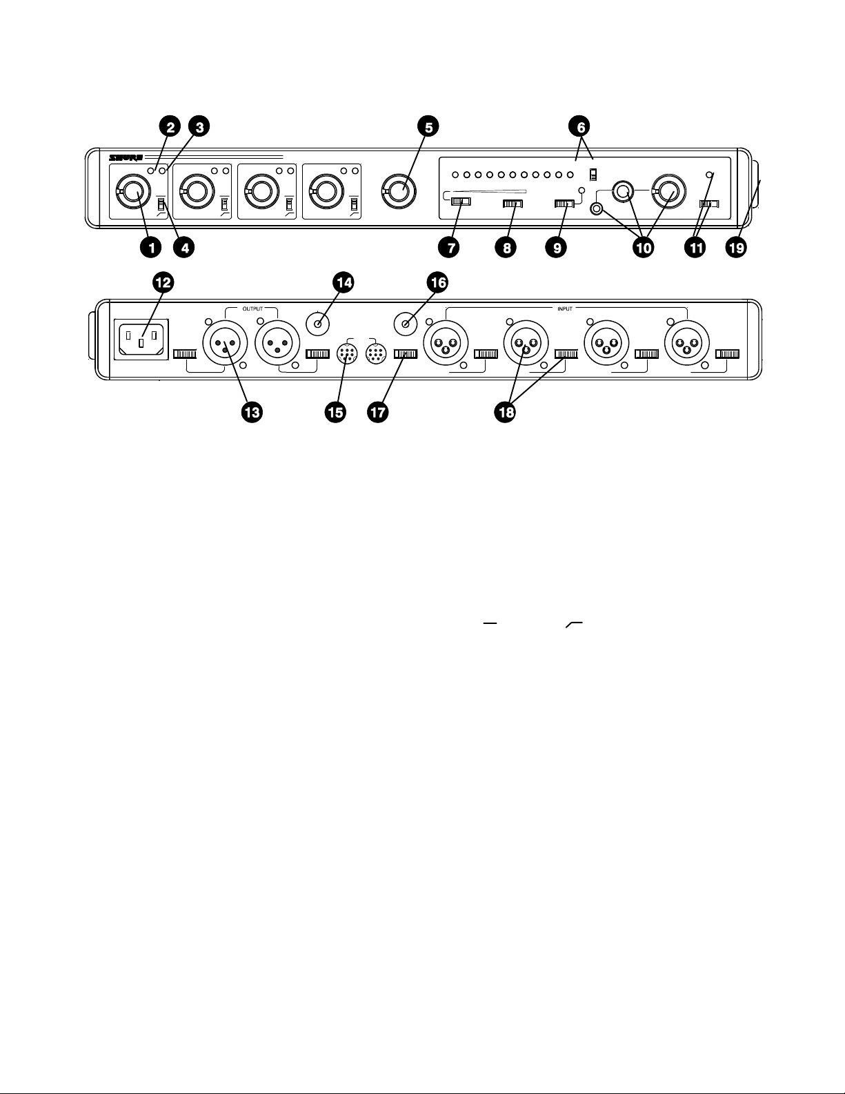
CONTROLS, CONNECTORS, INDICATORS
(See Figure 1)
1. Microphone Channel Gain Controls 1--4: At “0” position, mi-
crophone channel is removed from operation. Turning control
432 1
clockwise activates microphone channel and allows adjustment of microphone level.
2. Input Normal Green LED: Should flicker with normal speech
levels.
3. Input High Red LED: Should flicker only on loud speech
peaks.
4. Flat (
)/Low--Cut ( ) Slide Switches: Provide low--frequency rolloff to reduce undesirable low--frequency signals
such as wind noise.
5. MASTER Rotary Control: Determines the level of the combined input signals at Mic/Line, Tape and Phones outputs.
PULL FOR 1 kHz TONE position activates 1 kHz tone oscillator (tone level is determined by Master control setting). Oscillator signal appears at all outputs. When oscillator is not in use,
knob should be pushed in.
6. PEAK/VU Output Level Meter: Meter function is selected by
adjacent PEAK/VU slide switch. In PEAK switch position, meter indicates peak signal levels. In VU position, it indicates average signal levels, simulating a true VU meter.
7. BATTERY TEST Momentary Slide Switch: Operates in con-
junction with PEAK/VU Meter to indicate battery condition.With POWER s witch on and switch in momentary--on position, new set of batteries lights all green LEDs. Number of
green LEDs lit indicates approximate battery life remaining
when alkaline batteries are used. NOTE: POWER LED begins
flashing when total battery supply voltage drops to 10 Vdc (one
green LED lit).
8. MANUAL/AUTO Slide Switch: Selects manual or automatic
microphone operating mode. In MANUAL position, unit operates as a conventional microphone mixer. In AUTO position,
unused microphones automatically turn off.
2
Page 3

9. LIMITER IN Slide Switch: Activates fast--acting, peak--responding limiter circuit to cut overload distortion during loud
program intervals without affecting normal program levels.
The red limiter LED indicates limiting action.
1
10. PHONES
/4--inch and 3.5 mm Phone Jacks: Permit monitoring mixer output through most stereo or mono headphones.
PULL FOR MONITOR switch applies signal from rear--panel
MON IN 3.5 mm phone jack to headphones amplifier. When
switch is activated, mixer output signal does not appear in
headphones output. PHONES rotary control determines
headphone level in either case.
11. POWER Slide Switch: Applies ac or battery power to mixer
circuitry. Adjacent green LED indicates power--on status and,
in battery operation, flashes when total battery voltage drops
to 10 Vdc.
12. 100--120 VAC, 50/60 Hz 8W 3--Pin Power Connector: For
connection to 100 to 120 Vac,50/60 Hz power outlets (230 Vac
in the FP410E).
13. OUTPUT 3--Pin Male XLR Connectors: For connection to
one or two amplifiers, recorders or other mixers. Output signal
levels are individually switchable to Line level or low--impedance Mic level by adjacent individual MIC/LINE slide
switches. Both jacks provide the same signal information but
are electrically isolated.
14. TAP E OUT 3.5 mm Phone Jack: Provides output signal to
feed unbalanced aux--level inputs of most tape recorders and
amplifiers.
15. LINK IN/OUT 8--Pin miniature DIN Jacks: Using link
cables, these jacks permit virtually unlimited number of FP410
mixers to be stacked to achieve additional input capacity.
Jacks carry audio signals, MaxBus and Last Mic Lock --On information.
16. MON IN 3.5 mm Phone Jack: Sends external Aux or Line-level source to headphones amplifier without interrupting other
mixer functions. Jack is activated by pulling front--panel PULL
FOR MONITOR knob outward.
17. PHANTOM ON/OFF Slide Switch: Controls application of
14 Vdc phantom power for condenser microphones to all inputs. With switch on and INPUT MIC/LINE switches in MIC position, +14 Vdc is applied to pins 2 and 3 of each input XLR connector. NOTE: Phantom power can be internally set to 48 Vdc
(see Modifiable Functions section). When using other than
Shure condenser microphones, verify that voltage and source
resistance requirements are compatible (see Specifications).
18. INPUT 1-- 4 Female 3--Pin XLR Connectors: Permit con-
nection to balanced, low--impedance microphones or line--level sources. Adjacent MIC/LINEslide switches adjust inputs to
match source levels.
19. Battery Compartment: Accepts two 9--volt batteries for remote operation or as automatic backup in the event of ac power failure.
INSTALLATION AND OPERATION
Mixer Installation
Install the FP410 as follows. If the unit is to be placed on a
horizontal surface, attach the four supplied bumpers to the corners of the chassis bottom to prevent marring the surface.
If the FP410 is to be rack--mounted in a standard 483 mm
(19--inch) audio equipment rack, remove the two Phillips head
screws from each FP410 side panel, place the rack “ears” in
position at the sides (rack--mount holes facing forward), and
secure the ears with the previously removed Phillips head
screws. NOTE: The rack ears are asymmetrical; the wider ear
should be on your right (as you face the front panel) to permit
access to the battery compartment while the FP410 is in the
audio equipment rack. Install the rack--mounted FP410 in the
equipment rack and secure it with the four supplied rack -mount screws.
Make electrical connections as follows.
1. For battery operation, compress the release latches of the
battery drawer with thumb and forefinger, and withdraw the
drawer from the compartment. Observing battery polarity
markings, insert two fresh 9--volt batteries in the drawer
slots. With the Power switch on, s lide the Battery Test switch
to the right to determine battery condition. IMPORTANT:
Battery operating life is reduced when microphones are
phantom--powered—especially by 48 Vdc phantom powering. For ac operation, connect the power cord to a 100 to 120
Vac, 50/60 Hz source (FP410E: Connectto a 230 Vac, 50/60
Hz source).
2. Connect the microphones and/or line--level signal sources
to the Mic Input connectors (use conventional 2--conductor
shielded cables). Adjust Mic/Line switches as required for
incoming signal level.
3. If phantom --powered condenser microphones are used,
turn on the FP410’s Phantom Power s witch. NOTE: With
condenser microphones other than Shure, verify that voltage and source resistance requirements are compatible.
4. Connect one or both of the FP410 Outputs to the following
mixers, amplifiers or recorders. Make certain each Output
Mic/Line switch is in the proper position for the desired output levels.
5. If an unbalanced aux--level output is needed, connect it to
the Tape Out jack.
6. If additional FP410 mixers are to be linked to increase the
number of microphone inputs, connect them by means of
the Link In and Link Out jacks. Connect the LINK OUT of the
first mixer to the LINK IN of the next mixer, and so on. Leave
the LINK IN jack of the first mixer and the LINK OUT jack of
the last mixer unconnected. NOTE: Jacks are for linking
only, not for audio inputs or outputs.
7. If headphone monitoring of the FP410 mixed signal is required, connect mono or stereo headphones to one of the
front--panel Phone jacks (
1
/4--inch or 3.5 mm). Adjust the
Phone control knob for the desired loudness (after setting
the microphone Channel and Master Gain controls according to Operation section).
8. To monitor an external signal source, connect it to the rear-panel Mon In jack and pull the Phones control knob outward.
Adjust the Phones control and/or the external source level
control for the desired loudness.
3
Page 4
Operation
1. Turn on the Power switch and set the Manual/Auto switch to
Manual.
2. Set the Peak/VU meter to Peak or VU as desired.
3. The 1 kHz internal tone oscillator can be used to help align
the following equipment levels (master mixer, amplifier, recorder, etc.) to the output level of the FP410.The tone oscillator is activated by pulling the Master gain control outward.
Its level at the FP410 output is set by the Master gain control. After setting equipment levels, turn off the tone oscillator by pushing the Master gain control inward.
4. “Talk” the microphone connected to the FP410 Channel 1
input, and slowly raise the Channel 1 Gain control to the
point where the green LED flickers regularly with normal
speech, and the red LED only occasionally with louder
speech peaks.
5. Set the other FP410 channel gains in the same manner.
6. Set the Flat (
)/Low--Cut ( ) switches adjacent to each
Gain control as required. The low--cutposition reduces pickup of low--frequency room noise.
7. Set the Manual/Auto switch to Auto. In about one second,
unused microphone inputs will turn off and the level of an individual talker’s voice will rise above the background noise
and reverberation to become clearer and more intelligible.
8. Adjust the FP410 Master Gain control for the desired output
level, as indicated by the Peak or VU meter, or by the following equipment.
9. The FP410 is now ready for operation.
USING AN EQUALIZER/FEEDBACK
CONTROLLER WITH AN AUTOMATIC MIXER
When setting up a sound system which has an outboard
equalizer or feedback controller in the signal chain, set the
FP410 to MANUAL. This activates all microphone inputs, so
every possible feedback path is open. With the FP410 in
MANUAL mode, equalize the sound system and/or “Ring Out”
the room to set the feedback controller.
After equalization is complete, set the FP410 to AUTOMATIC mode. Remember that the input of an automatic mixer
drops by 3 dB every time the number activated inputs doubles.
When using an FP410 in MANUAL mode, the master output
drops by 9 dB when all 8 inputs are activated. Conversely, it
will rise by 9 dB when switched back to AUTOMATIC mode.
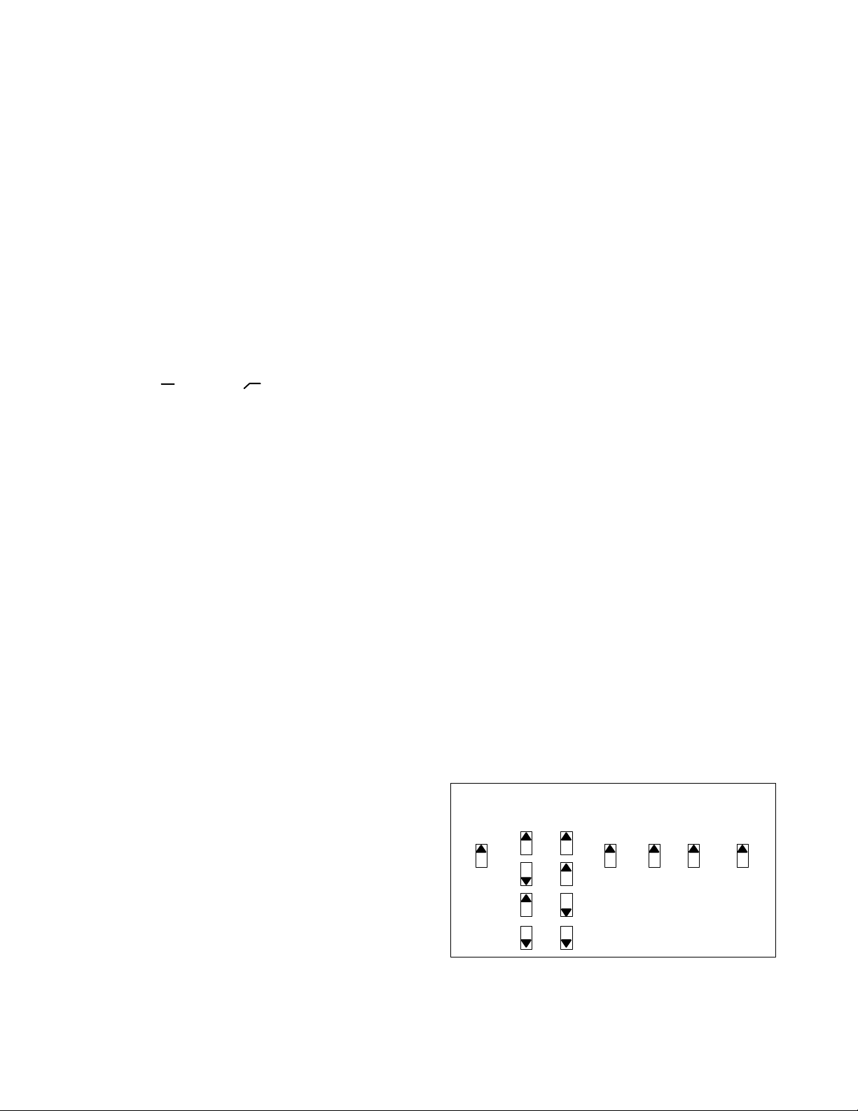
MODIFIABLE FUNCTIONS
The FP410 is ready for automatic or manual operation as
supplied. Additional versatility is provided by easily accessible
switches visible when the battery compartment is removed.
Note that the switches are all in the “up” position as supplied;
changes are made by moving the switch or s witches downward. The switch positions are illustrated by a label below the
battery compartment (see Figure 2).
VU Meter (Switch No. 1). Change the VU meter, supplied cal-
ibrated for +4 dBm = 0 VU, to +8 dBm = 0 VU by moving this
switch downward. (This switch does not affect calibration of
the LED output level meter in the Peak position.)
Limiter Threshold (Switch Nos. 2, 3). Change the limiter
threshold, the output level at which limiter action begins, from
the factory--set +16 dBm to either +8 dBm, +4 dBm or 0 dBm
output level by moving these switches as shown in Figure 2.
Off--Attenuation (Switch No. 4). Change the off-- attenua-
tion from 13 dB to infinite (
With the 13 dB setting, an unused microphone is 13 dB lower in
level than when it is activated. With the
microphone is completely off.
) by moving this switch downward.
setting, an unused
Hold Time (Switch No. 5). Change the hold time, the duration
of time an activated microphone (which is not locked on) remains on after the talker stops talking, from 0.4 seconds to 1.0
second by moving this switch downward.
Last Mic Lock--on Defeat (Switch No. 6). The last mic
lock--onfeature keeps the most recently activated microphone
open until a newly activated microphone takes its place. It can
be defeated so that all microphones automatically turn off after
the hold time by moving this switch downward.
Phantom Power (Switch No. 7). Phantom power for con-
denser microphones, normally 14 V, can be changed to 48 V
by moving this switch downward. CAUTION: Make certain the
condenser microphones to be used are c ompatible with the
selected voltage. If the microphones can operate properly with
14 V phantom power, that position should be used to avoid excessive battery drain.
INTERNAL MODIFIABLE FUNCTIONS
METER
0VU
+4
LIMITER
THRESHOLD
+16
OFF-
ATTEN
13 dB IN0.4 SEC +14 V
HOLD
TIME
LAST MIC
LOCK-ON
PHANTOM
POWER
+8 OUT1.0 SEC +48 V
+8
+4
0
∞
MODIFIABLE FUNCTION SWITCHES
FIGURE 2
4
Page 5

WARNING
Voltagesin this equipment are hazardous to life. No user--serviceable parts inside. Refer all servicing to quali fied service personnel.
In addition to the user--modifiable functions described
above, the FP410 is designed so that many of its functions can
be modified by a qualified technician. Instructions on implementing these modifications are provided in the FP410 Service Manual which is obtainable from Shure. These modifications are:
1. Change Monitor In sensitivity.
2. Change Tape Out level.
3. Change Off--Attenuation value.
4. Change low--cut filter frequency.
5. Change Peak meter attack and decay time constants.
6. Change 0 VU Meter calibration to level other than +4 or +8
dBm.
7. Change Limiter threshold beyond the positions permitted by
Switches 2 and 3 (see Figure 2).
8. Change to permanently lock one or more microphones on.
9. Change to permanently prevent one or more microphone
channels from activating.
10. Change the preset Hold Time values.
11. Change the Monitor In jack to an Aux In jack function for
cascading mixers or creating a “mix--minus”.
12. Change to provide reduced--level program feed in head -
phones when Pull For Monitor switch is activated.
13. The FP410 can be changed to operate from 230 Vac,50/60
Hz power. Similarly, the FP410E can be changed to operate
from 100 to 120 Vac, 50/60 Hz mains voltage.
WARNING
The safety certifications of the FP410 and FP410E do not
apply when the operating voltage is changed from the
factory setting.
ADDITIONAL INFORMATION
Limiter
The front--panel Limiter switch turns on a fast--acting,peak-responding limiter circuit that cuts overload distortion during
loud program intervals without affecting normal program levels. When the switch is In (operating), the FP410 output is limited to approximately +16 dBm. Increasing the individual or
Master gain controls will increase the average output and the
amount of limiting. The limiter threshold can be changed from
its factory setting as described in the Modifiable Functions
section. The front--panel red LED adjacent to the Limiter
switch indicates limiter action.
Linked Mixers
The FP410 provides four microphone inputs. If additional
mic inputs are needed, more FP410s (over 25, if necessary)
can be “linked” using link cables of the type supplied. A setup
like this can provide over 100 mic inputs. As long as the link
jacks of all mixers are connected (out --to--in, s equentially,
leaving one Link In and one Link Out jack unconnected), the
automatic mixing functions will be shared by all units.
When FP410 mixers are linked, Shure Intellimix control
functions are also linked so that a single multi--microphone
system is created. All input signals (except the Monitor In signal) appear at all linked mixer outputs. There is no master/
slave relationship.
The output--related controls and functions of each linked
mixer are post --link and do not affect the signals appearing at
other linked mixer outputs. Each mixer’s output controls may
be set differently to obtain different results. These controls are:
Master level control, 1 kHz Tone Oscillator, Peak/VU Meter
switch, Limiter In and Limiter Threshold switches, Phone level
and Monitor control, and Off--Attenuation switch. NOTE: The
actual off--attenuation in the 13 dB switch position increases,
as more mixers are linked. This reduces excessive noise and
reverberation contributed by the increased number of typically
“off” microphones.
The input--channel--related controls and functions of each
linked mixer are pre --link and do not affect the input channels of
other linked mixers. The effect of these input controls is reflected in the mixed output signals of all the linked mixer outputs. These controls are: Input channel levels controls and
Low--Cut switches, Manual/Auto switch, Phantom On/Off
switch, Phantom Voltage Selector switch, Hold Time s witch,
and Last Mic Lock--On switch.
Link Cables
Additional link cables can either be purchased (Shure Part
No. 95A1143; 305 mm—12 in.) or constructed using desired
lengths of high--quality, 7--conductor, shielded cable (pin 1:
shield) with 8--pin mini DIN connectors on each end. The maximum length of a link cable will depend on the grounding considerations of this unbalanced line.
FP410 and Mixing Consoles
The FP410 can be used in conjunction with large mixing
consoles to provide automatic mixing for talk shows, panel dis cussions, and nightly news shows. Large consoles have channel insert jacks so that external signal processing devices can
be patched into individual channel signal paths. These jacks
are normally line level.
The FP410 can be fed from these insert jacks and the
FP410 output then fed to a submaster fader on the console.
This arrangement allows the operator complete control of
each channel via the console’s input control strip, while the the
FP410 keeps the number of open microphones to a minimum,
relieving the operator of having to open and close mic channels.
SUPPLIED ACCESSORIES AND REPLACEMENT
PARTS
Battery Tray Assembly 90GJ2600.....................
Bumper (Foot) Kit (4 in kit)) 90S8100..................
Control PC Board Assembly 90B8368A................
Knob, Master & Phones 95A8238.....................
Knob, Channel Gain 95B8238........................
Line (Power) Cord (FP410) 95A8231..................
Line (Power) Cord (FP410E) 95A8247.................
Link Cable 95A1143.................................
Left Rack--Mount Bracket 53A8252....................
Right Rack--Mount Bracket 53A8253..................
5
Page 6

SPECIFICATIONS
Measurement Conditions (unless otherwise specified): Line
voltage 120 Vac, 60 Hz (FP410E: 230 Vac,50/60 Hz); full gain;
1 kHz, one channel activated; output terminations: Line 600τ,
Mic 150
sleeve); Auto mode
Frequency Response (controls centered)
Voltage Gain
Inputs
Outputs
Total Harmonic Distortion (controls centered [5], +4 dBm at
Line output)
τ, Tape 50 kτ, Phones 200τΕtip--sleeve and ring--
25 Hz to 20 kHz, +0.5,--2 dB (any input to any output)
Output
Input Line Mic
Low--impedance
mic
τ)
(150
Line 42 dB -- 8 d B 46 dB 23 dB
Monitor — — 9dB —
Input
Mic
Line
Monitor
Output
Mic Any low--im-
Tape
Head-
phones
Line
93 dB 43 dB 97 dB 74 dB
Impedance
Designed
for use with
19--600τ 900τ
10 kτ 66 kτ
1kτ 25 kτ
Impedance
Designed
for use with
pedance
mic input
>10 kτ 1kτ
8--200τ,
τ rec-
200
ommended
600τ 100τ
Head-
phone
Actual (In-
ternal)
Actual (In-
ternal)
0.5τ
500τ
Tape
Input Clipping Level
--15 dBV
To >+26
dBV
+21 dBV
Output
Clipping
Level
--31 dBV (28
mV) min.
--2 dBV (800
mV)
+6 dBV (2.0
V)
+19 dBm
(6.9 V) min.
0.25%,50Hzto20kHz
Hum and Noise
Equivalent Input Noise --128.5 dBV...................
Equivalent Input Hum and Noise --128.5 dBV..........
Output Noise (300 Hz to 20 kHz; channel controls full counterclockwise)
Master full counterclockwise --88 dBV..............
Master full clockwise --71 dBV.....................
Output Hum and Noise (20 Hz to 20 kHz; channel controls
full counterclockwise)
Master full counterclockwise --74 dBV..............
Master full clockwise --70 dBV.....................
Common Mode Rejection
65 dB minimum with input of --20 dBV at 100 Hz
Polarity
Pin 2 of balanced inputs and outputs are in phase with tip
connections of unbalanced inputs and outputs
Input Channel Activation
Attack Time 4 msec.................................
Hold Time 0.4 sec (switchable to 1.0 sec).............
Decay Time 0.5 sec................................
Off--Attenuation
13 dB, fixed (switchable to
creases as additional mixers are linked)
Overload and Shorting Protection
Shorting outputs, even for prolonged periods, causes no
damage. Microphone inputs are not damaged by signals up
to 3 V; Line and Monitor inputs by signals up to 20 V
Low--Cut Filters
6 dB/octave rolloff below 170 Hz
Limiter
Threshold +16 dBm (switchable to +8, +4, 0 dBm)......
Attack Time 3 msec.................................
Recovery Time 350 msec...........................
Indicator Lights when limiting is occurring..............
Meter
VU Meter Calibration: 0 VU = +4 dBm (switchable to +8
dBm)
Peak Meter:
Rise Time: 2.0 msec time constant (0.9 msec/LED step)
Decay Time: 180 msec time constant (83 msec/LED step)
Tone Oscillator
10%, THD <0.5%
1kHz,
Phantom Power
14 Vdc open--circuit, 1 k
in Mic position only (internally switchable to 48 Vdc, 4.5 k
series resistance)
)(single mixer; attenuation in-
τ series resistance, input switches
τ
6
Page 7

Operating Voltage
AC Operation: 100 to 120 Vac rated nominal, 80 to 132 Vac
fully operational (FP410); 230 Vacrated nominal, 160 to 264
Vac fully operational (FP410E), 50/60 Hz, 8 W
DC Operation: 18 Vdc nominal at 25 mA typical no --signal,
33 mA typical at 0 VU (+4 dBm) output with 600
minimum; battery life approximately 12 hours with alkaline
batteries at +4 dBm output in continuous use at room temperature; two 9--volt batteries (type NEDA 1604A)
Temperature Range
Operating --18
Storage --29
to 57 C(0 to 135 F).............
to 71 C(--20 to 160 F)...............
τ load; 6 Vdc
Questions &Answers
Questions about your FP410 installation? This section lists
the most common questions asked about Shure’s automatic
microphone systems. Maybe your question is among the following. If not, contact Shure’s Customer Service Department.
Q. Why don’t I get any sound output from my FP410?
A. Assuming that your power amp, tape deck, speakers, etc.
are good, possibly it’s because:
The Channel or Master Gain controls are turned down,
A microphone is not connected,
A rear--panel Mic/Line input or output switch or the Phan-
tom On --Off switch is improperly set,
The FP410 isn’t plugged in or doesn’t have batteries in-
stalled, or
The Power switch isn’t on.
Check these items and make the required correction.
Q. Still doesn’t work. Why?
A. Maybe you have a defective microphone or cable. While listening to headphones plugged into one of the front--panel
Phone jacks, try replacing the suspect microphone or cable
with one known to be good.
Q. Why does a microphone turn on or off erratically, causing
speech dropouts?
A. Excessive room noise (such as from air--handling or audio-visual equipment) can be a cause. Reduce the room noise, the
proximity of the noise to any mic, and/or the talker--to--mic distance. A loud talker close to their microphone or with their
Channel Gain control set too high can sometimes inhibit proper microphone activation by a “weaker” talker who is too far
from their microphone or has their Channel Gain control set
too low. Balance the microphones by repositioning and/or resetting the Channel Gain controls in accordance with the Op-
eration section.
IMPORTANT: Best results are generally obtained when the
Last Mic Lock--On is not defeated and the Off--Attenuation is
Overall Dimensions
44.5 mm H x 368 mm W x 210 mm D (1
ches)(not including feet)
Net Weight
2.27 kg (5 lb)
Certifications
FP410: Listed by Underwriters Laboratories, Inc., listed as
Certified by Canadian Standards Association.
FP410E: Conforms to European Union directives, eligible to
bear CE marking;VDE GS-certified to EN 60 065; meets European Union EMC Immunity Requirements (EN 50 082-1,
1992).
13 dB (modifiable function switches up). Difficult situations
may be aided by changing the Hold Time from 0.4 to 1.0 second (modifiable function switch down).
Q. Why am I getting howling through my loudspeakers?
A. For the same reason that howling is present in any PA system: your mics are picking up the speaker sound and reamplifying it. Move the speakers or mics, or turn down the gain controls, to avoid the howling. Automatic operation does provide
more output level before howling than manual operation, but
the system still can howl.
Q. Why does the FP410 output sound distorted?
A. The Channel, Master or Phones Gain control may be set too
high. Set the Channel Gain according to the Operation section.
Set the Master Gain to avoid excessive red LED indications on
the Output Level meter, or switch the Limiter in. Turn down the
Phones control. Check the following equipment levels.
Q. Why does the speech level go up when I switch from Manual to Automatic operation?
A. This is normal and proper operation for any automatic mixer.When switched to Automatic, the FP410 attenuates any input channel not being used. Internally, this removes the inactive channels from the FP410 mix bus. This action increases
the perceived level of any active input channel. For example,
the audio gain increase will be 6 dB when going from four to
only one activated microphone channel.
Q. Why is one of my four mics very noisy?
A. Assuming the mic is operating properly (you can check this
by substituting with another mic), you probably have a constant noise source such as air--moving equipment or a defective fluorescent light ballast in the trouble area. This ambient
noise source can be unnoticed until it’s picked up by a mic:
then it’s extremely annoying. If you can’t repair,turn off or lower
the noise source, try relocating the mic to eliminate or at least
lower the noise. If this is not possible, use the FP410 in the
Manual mode to avoid microphone activation problems and
accept the noisy output.
3
/4x141/2x81/4in-
7
Page 8
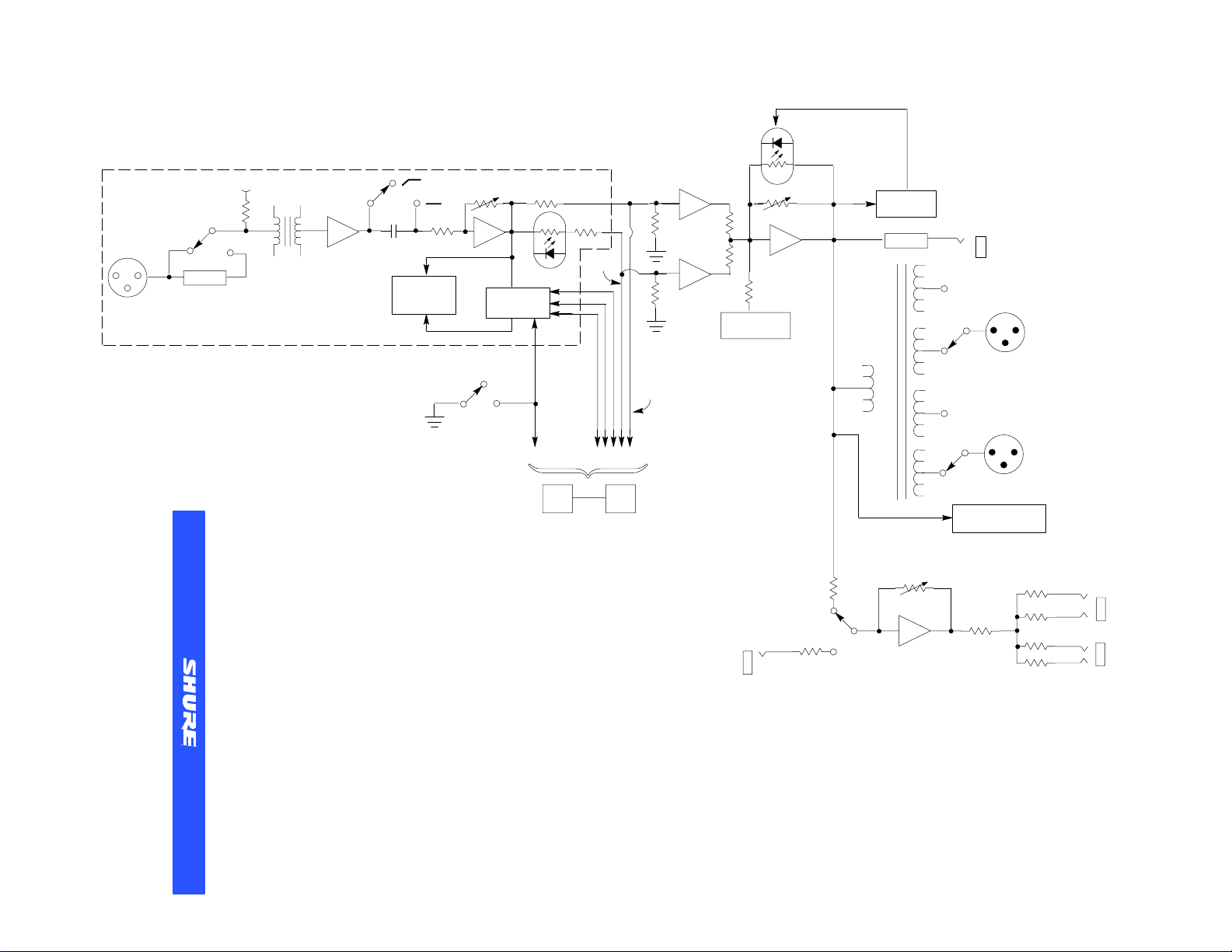
BALANCED
MIC/LINE
INPUT
PHANTOM POWER
LINE
MIC
ATTEN
CHANNEL 1 (TYPICAL)
LOW-CUT CHANNEL LEVEL
CHANNEL
LEVEL
INDICATORS
INTELLIMIX
CONTROL
GATED
SIGNALS
MASTER LEVEL
1 kHz
OSCILLATOR
LIMITER/
INDICATOR
ATTEN
MIC
TAPE
OUT
32
Shure Incorporated
222 Hartrey Avenue, Evanston IL 60202-3696
Phone: 847 866-2200 FAX: 847 866-2279
In Europe, Phone: 49-7131-72140 FAX: 49-7131-721414
In Asia, Phone: 852–2893–4290 FAX: 852–2893–4055
Internationally, Phone: 847 866-2200 FAX: 847 866-2585
The Sound of Professionals...Worldwide
AUTO
MANUAL
CHANNELS 2,3,4
IN OUT
LINK JACKS
NON-
GATED
SIGNALS
MONITOR
IN
FP410 BLOCK DIAGRAM
LINE
MIC
LINE
PEAK/VU/BATTERY
HEADPHONES
LEVEL
BALANCED
MIC/LINE
OUTPUTS
METER
HEADPHONES
Page 9

Français
L’appareil Shure modèle FP410E est un mélangeur de microphone automatique. Il est conçu pour être utilisé dans une large
gamme d’applications de prise de sons à partir de plusieurs microphones.
concept de fonctionnement sur lequel est basé le mélangeur modèle FP410E. Il permet d’obtenir un mixage automatique sans défaut grâce à la combinaison des trois fonctions très particulières
suivantes:
tre un bruit de fond constant (tel que le bruit d’un système de climatisation) et un sons changeant rapidement (tel que la parole). Cette
fonction ajuste de façon continue le seuil d’activation pour que
seuls les niveaux de la voix dont l’intensité est plus élevée par rapport à celle du bruit de fond mettent en fonction un canal du mélangeur FP410E.
la voix d’un speaker est captée par plusieurs microphones à la fois.
Cette fonction accomplit ceci en contrôlant le nombre de microphones qui peuvent être mis en fonction pour une source sonore unique. A vec la fonction MaxBus, un speaker ne met en fonction qu’un
seul canal du mélangeur FP410E même si plusieurs microphones
captent la voix de ce speaker.
tient un mixage sonore parfait en maintenant le fonctionnement du
dernier microphone mis en fonction jusqu’à ce qu’un autre microphone soit mis en fonction pour le remplacer . Sans la fonction Last
Mic Lock–On, l’interruption de la conversation pendant une longue
période risque d’entraîner l’arrêt de tous les microphones et on aurait l’impression d’avoir perdu le signal sonore. La fonction Last Mic
Lock–On permet d’assurer en permanence la présence de l’ambiance d’arrière–plan.
certain nombre de speakers, ont toujours posés des problèmes
aux techniciens du sons. Si plusieurs micros sont utilisés, le signal
sonore peut varier en fonction de la proximité ou de l’éloignement
de chaque speaker par rapport au micro. En effet, la voix d’un speaker qui est plus proche du micro par rapport à un autre speaker qui
est plus éloigné d’un autre micro, est plus sonore et plus claire. Les
voix des speakers les plus éloignés des micros, sont résonantes et
réverbérantes car, une très faible partie de leur sons vocal direct
atteint les microphones. Si le nombre de micros utilisés est beaucoup plus important, le bruit de fond et la réverbération qui seront
captés sont également importants. Entre autre, le gain est réduit
avant le réaction (feedback) en cas d’utilisation d’un système de
sonorisation (amplificateur de puissance).
plusieurs caméras sont toutes focalisées sur un même sujet. Si les
signaux de ces caméras sont combinés, il en résulte une image
floue. Lorsque plusieurs microphones sont ouverts pour un seul
speaker, i l en résulte un signal sonore parasite. Cependant, il n’est
pas souvent pratique de mettre en fonction des micros lorsque leur
utilisation s’avère nécessaire et de les mettre hors fonction dans le
cas contraire. La solution à tous ces problèmes est apportée par le
mélangeur automatique FP410E.
dine) tout microphone qui n’est pas utilisé, réduisant énormément
l’excès de réverbération et les problèmes de réaction associés
avec l’utilisation de plusieurs microphones et les techniques de
mixage classiques. Lorsqu’un nouveau speaker commence à parler, le mélangeur FP410E sélectionne et met en marche immédiatement et de manière silencieuse le microphone le plus approprié.
Le traitement du signal électronique selon le concept
Mix
Shure IntelliMix
•
Seuil adaptable au bruit,
•
MaxBus et
•
Verrouillage du dernier micro (Last Mic Lock–On).
La fonction du seuil adaptable au bruit peut faire la distinction en-
La fonction MaxBus élimine la mauvaise qualité sonore lorsque
La fonction Verrouillage dernier micro (Last Mic Lock–On) main-
Les situations où plusieurs micros doivent être utilisés par un
Ce phénomène est en quelque sorte similaire à une situation où
Le mélangeur FP410E atténue automatiquement (met en sour-
permet au mélangeur FP410E de fournir une prise de sons na-
correspond au nouveau et remarquable
Shure Intelli-
turelle et nette. Le mélangeur FP410E réduit énormément les problèmes de sons “sourd” ou “trouble”, les problèmes dûs à un niveau
de sons trop faible (à cause de la réaction ou du “hurlement”) et
ceux des erreurs commises par les opérateurs. En fait, les erreurs
des opérateurs sont virtuellement éliminées, car le FP410E ne fait
appel ni à u n opérateur ni à un technicien pour subir un réglage continuel — après la mise au point, il devient entièrement auto–
suffisant.
Le FP410E peut faire l’objet d’une multitude d’applications dans
le domaine de la production vidéo et de l’enregistrement sonore, la
radiodiffusion et de l’amplification du sons. Quelque soit le domaine d’application de prise de sons où plusieurs microphones sont
requis, le FP410E améliore la qualité du sons de manière substantielle. Le passage du fonctionnement manuel au fonctionnement
automatique, permet à la voix d’un speaker de s’élever au–dessus
du bruit de fond et de la réverbération pour devenir beaucoup plus
claire et plus intelligible à la fois.
Chaque FP410E supporte au maximum quatre microphones ou
signaux du niveau de la ligne. Il est possible d’utiliser n’importe
quel type de microphone symétrique de haute qualité et de faible
impédance qui utilise un transducteur condensateur* ou dynamique (y compris les microphones canon et sans fils). Des mélangeurs FP410E supplémentaires peuvent être interconnectés à l’aide des jacks de connection du panneau arrière. L’utilisation du
commutateur de sélection du panneau avant représente également une option d’exploitation manuelle complète.
Le mélangeur FP410E est fourni avec des tampons–
amortisseurs (pieds) optionnels utilisables sur des surfaces plates,
un câble court pour connecter deux mélangeurs FP410E et un kit
de montage en baie pour son installation dans une baie standard
de 483 mm pour les équipements audio.
Le FP410E est prévu pour alimentation à 230 V c.a. (fusible de
ligne de 0,05 A). Son cordage se termine par une prise c.a. Schuko.
*Automoteur ou alimenté en tension fantôme de 14 ou 28 Vcc.
Caractéristiques
•
Fiable, à action rapide, sélection de microphones sans bruit — à
réglage automatique en fonction des variations du bruit de fond
de la salle.
•
Les commandes de l’organe de contrôle principal et du gain du
panneau avant fonctionnent de façon similaire que celles des
mélangeurs classiques.
•
Un temps d’arrêt sélectif permet de maintenir les microphones
en fonction pendant les pauses courtes durant un discours.
•
Blocage d’atténuation sélectif dont le résultat est un fonctionne-
ment parfait.
•
Réglage automatique du gain au fur et à mesure que des micro-
phones supplémentaires sont mis en fonction.
•
Le circuit Dernier micro verrouillé (“Last Mic Lock–On”) permet
de maintenir en fonction un microphone au moins à tout moment
— maintient l’ambiance acoustique et empêche les variations
perturbatrices du bruit de fond.
•
Réponse à de larges fréquences linéaires, et faible distorsion
pour des signaux de sortie pouvant atteindre +18 dBm.
•
Capacité de liaison des systèmes ayant plus de 25 mélangeurs
et plus de 100 microphones.
•
Indication à base de diodes électroluminescentes (LED) des ni-
veaux de mixage des canaux, des niveaux du signal de sortie et
de l’action du limiteur.
•
L’amortissement automatique permet d’empêcher la gêne due
au crépitements et l’endommagement des haut–parleurs lors-
que le système est mis en/hors fonction.
9
Page 10

•
Transformateur — signaux d’entrée et de sortie symétriques
commutables sur secteur—ou au niveau du microphone.
•
Jacks d’entrée d’écoute et de sortie pour enregistrement (niveaux accessoires) distincts.
•
Jacks pour casque d’écoute situés sur le panneau avant avec réglage de volume.
•
Commutateur de déconnection automatique situé sur le panneau avant qui sert pour le fonctionnement manuel.
•
Alimenté en courant alternatif ou à l’aide de deux batteries de 9V.
•
Alimentation en fantôme commutable de 14V et 48V pour les microphones à condensateur.
•
Homologation VDE pour la sécurité conformément à DIN VDE
0860/05.89, harmonisation avec CENELEC HD 195 S6
COMMANDES, CONNECTEURS, INDICATEURS (Voir Figure 1)
1. Commandes du gain des canaux du microphones 1–4: A la position “0”, le canal du microphone est mis hors fonction. Lorsque le
bouton de commande est tourné vers la droite, le canal du microphone est mis en fonction et permet de régler le niveau du microphone.
2. Diode électroluminescente (LED) verte indicatrice du signal
d’entrée normal: Doit scintiller lorsque les niveaux des signaux
sonores sont normaux.
3. Diode électroluminescente (LED) rouge indicatrice de signal
d’entrée fort: Doit scintiller lorsque les signaux sonores présentent des crêtes.
4. Commutateurs à coulisse pour fréquences linéaire/Filtre passe–
haut (Flat [
tissement des basses fréquences pour réduire les signaux à
basse fréquence indésirables tels que le bruit du vent.
5. Organe de commande rotatif principal (MASTER): Détermine le
niveau des signaux d’entrée combinés au niveau des sorties
Mic/Line, Tape et Phones. Le réglage de l’organe de commande
sur la position PULL FOR 1 kHz TONE met en fonction l’oscillateur d’une tonalité de 1 kHz (le niveau de la tonalité est déterminé
par le réglage de l’organe de commande principal). Le signal de
l’oscillateur apparaît au niveau de toutes les sorties. Enfoncer le
bouton de commande lorsque l’oscillateur n’est pas en fonction.
6. Indicateur de niveau de sortie crête/VU (PEAK/VU): Le commutateur adjacent à coulisse PEAK/VU, permet de sélectionner la
fonction de l’indicateur. Lorsque le commutateur est positionné
sur PEAK, l’indicateur indique les crêtes des signaux. Lorsqu’il
est positionné sur VU, l’indicateur indique les signaux de niveaux
moyens, simulant un volumètre réel.
7. Commutateur à coulisse sans maintien de test des batteries
(BATTERY TEST): Fonctionne en conjonction avec l’indicateur
PEAK/VU pour indiquer l’état de la batterie. En actionnant le
commutateur POWER et le commutateur à coulisse en position
de maintien, un jeu de batteries neuves entraîne l’allumage de
toutes les diodes électroluminescentes vertes. La durée de service des batteries est déterminée de façon approximative en
fonction du nombre de diodes allumées lorsque des batteries alcalines sont utilisées. NOTE: La diode POWER LED commence
à clignoter lorsque la tension des batteries diminue et atteint 10
Vcc (une seule diode verte s’allume).
8. Commutateur à coulisse des modes de fonctionnement manuel
et automatique (MANUAL/AUTO): Sélectionne le mode de fonctionnement manuel ou automatique du microphone. En position
MANUAL, le dispositif fonctionne comme un mélangeur de microphones classique. En position AUTO, les microphones inutilisés sont automatiquement mis hors fonction.
9. Commutateur à coulisse du limiteur (LIMITER IN): Met en fonction le circuit du limiteur à action rapide qui réagit aux crêtes des
signaux pour éliminer la distortion de surcharge durant les intervalles sonores d’un programme sans affecter les nouveaux ordinaires de ce dernier. La diode électroluminescente rouge indique l’action limite.
]/Low–Cut [ ]): Permettent d’augmenter l’amor-
10. Jacks d’écoute de 3 mm (PHONES): Permettent de contrôler le
signal de sortie du mélangeur à l’aide de la majorité des casques
d’écoute stéréo ou mono. Le commutateur PULL FOR MONITOR applique le signal du jack d’écoute MON IN (3,5 mm) du
panneau arrière à l’amplificateur du casque d’écoute. Lorsque le
commutateur est mis en fonction, le signal de sortie du mélangeur n’est pas perçu à la sortie du casque d’écoute. L ’organe de
commande rotatif PHONES détermine le niveau du signal du
casque d’écoute.
11. Commutateur à coulisse d’alimentation (POWER): Permet de
sélectionner l’alimentation des circuits du mélangeur en courant
alternatif (secteur) ou en courant continu (batteries). La diode
électoluminescente verte adjacente indique que le mélangeur
est alimenté et en cas d’alimentation à l’aide de batteries, elle
commence à scintiller lorsque la tension totale baisse et atteint
10 Vcc.
12. Fiche mâle à 3 broches pour source d’alimentation de 230
VCA, 50/60 Hz 8W: Permet de brancher l’appareil à des prises
d’alimentation de 230 Vca, 50/60 Hz.
13. Connecteurs XLR mâles à 3 broches de sortie (OUTPUT): Permettent de connecter un ou deux amplificateurs, des appareils
d’enregistrement ou d’autres mélangeurs. Les niveaux du signal
de sortie peuvent être commutés manuellement sur le niveau de
la ligne ou sur le niveau de faible impédance du microphone à
l’aide des commutateurs à coulisse adjacents MIC/LINE. Les
deux jacks fournissent les mêmes informations relatives au signal, cependant, ils sont isolés électriquement.
14. Jack d’écoute de 3,5 mm pour enregistrement (TAPE OUT):
Permet de transférer le signal de sortie pour alimenter la plupart
des appareils d’enregistrement et des amplificateurs.
15. Jacks DIN miniature de connexion à 8 broches (LINK IN/OUT):
Ces jacks permettent de connecter à l’aide de câbles de connexion, virtuellement, un nombre illimité de mélangeurs FP410E
pour atteindre une capacité d’entrée supplémentaire. Les jacks
portent les signaux sonores, et les informations MaxBus et Last
Mic Lock–On.
16. Jack d’écoute de 3,5 mm pour entrée mono (MON IN): Transmet le signal aux accessoires externes ou le signal de la source
niveau ligne à l’amplificateur du casque d’écoute sans interrompre d’autre fonctions du mélangeur. Le jack est actionné en tirant
vers l’avant le bouton PULL FOR MONITOR situé sur le panneau avant.
17. Commutateur à coulisse d’alimentation en fantôme (PHAN-
TOM ON/OFF): Permet de contrôler l’application de l’alimentation en fantôme de 14 Vcc pour les condensateurs des microphones au niveau de toutes les entrées. En mettant le
commutateur sur la position ON et le commutateur INPUT MIC/
LINE sur la position MIC, la tension 14 Vcc est appliquée aux
broches 2 et 3 d e chaque connecteur d’entrée XLR. NOTE: L’alimentation en fantôme peut être réglée à partir de l’intérieur à 48
Vcc (voir le chapitre
sez des microphones de condensateurs qui ne sont pas fabriqués par Shure, vérifiez que la tension et la résistance de la source soient conformes aux caractéristiques (Voir
18. Connecteurs femelles XLR à 3 broches (INPUT 1–4): Permet-
tent la connexion des microphones symétriques de basse impédance ou des sources du niveau de la ligne. Les commutateurs
à coulisse adjacents MIC/LINE permettent de régler les niveaux
des entrées pour les mettre au même niveau que ceux de la
source.
19. Compartiment des batteries: Prend deux batteries de 9 V pour
l’exploitation à distance ou pour le remplacement automatique
en cas de panne du secteur.
Ce produit n’est pas complètement déconnecté de l’alimentation de réseau lorsque le disjoncteur est sur Arrêt.
Fonctions modifiables
VEUILLEZ PRENDRE NOTE
). Lorsque vous utili-
Spécifications
).
10
Page 11

INSTALLATION ET FONCTIONNEMENT
Installation du mélangeur
Installez le mélangeur FP410E comme suit. Si l’appareil doit être
installé sur une surface horizontale, fixez les quatre tampon–
amortisseurs fournis au niveau des coins de la partie inférieure du
châssis pour éviter d’endommager la surface.
Si le FP410E doit être installé dans une baie standard de 483 mm
pour équipements audio, enlevez les deux vis à fentes en croix
(tête Phillips) de chacun des panneaux latéraux de FP410E. Placez les crampons de la baie sur les côtés (les orifices de montage
de la baie dirigés vers l’avant) et serrez les crampons en utilisant
les vis Phillips qui ont été enlevées précédemment. NOTE: Les
crampons de la baie ne sont pas symétriques; le plus large crampon doit être installé sur le côté droit lorsque vous faite face au panneau avant pour avoir accès au compartiment des batteries une
fois que l’appareil est installé dans la baie pour équipement audio.
Installez l’appareil FP410E monté en baie dans la baie pour équipements audio et fixez–le en utilisant les quatres vis de montage
fournies.
Les connexions électriques doivent être effectuées comme suit.
1. Pour le fonctionnement à l’aide des batteries, appuyez sur les
loquets de déclenchement du tiroir des batteries avec le pouce et
l’index et retirez le tiroir du compartiment. Insérez deux batteries
neuves de 9 V dans le tiroir en faisant attention à la polarité des
batteries. Avec le commutateur d’alimentation en position ON,
faites coulisser le commutateur de contrôle des batteries vers la
droite pour déterminer l’état des batteries. IMPORTANT: L a d u -
rée de service des batteries est réduites lorsque l’alimentation
des microphones est une alimentation en fantôme de 48 Vcc en
particulier. Pour le fonctionnement en courant alternatif, bran-
chez le câble d’alimentation à une source de 230 Vca, 50/60 Hz.
2. Connectez les microphones et/ou les sources des signaux du ni-
veau de la ligne aux connecteurs d’entrée des microphones (uti-
lisez des câbles classiques blindés à deux conducteurs). Réglez
les commutateurs MIC/Line en cas de besoin pour le niveau du
signal d’entrée.
3. Si des microphones de condensateurs alimentés en fantôme
sont utilisés, mettez en fonction le commutateur d’alimentation
en fantôme de FP410E. NOTE: Si les microphones de conden-
sateurs utilisés ne sont pas fabriqués par SHURE, assurez–
vous que la tension et la résistance de la source soient confor-
mes aux spécifications.
4. Connectez une ou les deux sorties de FP410E aux mélangeurs,
amplificateurs et appareils d’enregistrements. Assurez–vous
que chaque commutateur de sortie Mic/Line soit sur la position
correcte pour les niveaux de sortie désirés.
5. Si une sortie auxiliaire non symétrique s’avère nécessaire,
connectez–la au jack de sortie Tape Out.
6. Si des mélangeurs FP410E supplémentaires doivent être bran-
chés pour augmenter le nombre d’entrées du microphone,
connectez–les au moyen des jacks LINK IN et LINK OUT. Con-
nectez le jack LINK OUT du premier mélangeur au jack LINK IN
du mélangeur suivant et ainsi de suite. Ne connectez pas le jack
LINK IN du premier mélangeur et le jack LINK OUT du dernier
mélangeur. NOTE: Les jacks sont destinés à la connexion seule-
ment, mais pas pour les entrées ni les sorties audio.
7. Si un casque d’écoute pour contrôler le signal mélangé de
FP410E est requis, connectez les cordons pour casque stéréo
ou mono à l’un des jacks PHONE du panneau avant (1/4 pouce
ou 3,5 mm). Réglez le bouton de commande PHONE selon le vo-
lume sonore désiré (après avoir réglé les commandes Master
Gain et Channel du microphone conformément au chapitre
Fonctionnement
8. Pour contrôler une source d’un signal externe, connectez–la au
jack Mon In du panneau arrière et tirez le bouton de contrôle Pho-
nes vers l’extérieur. Réglez le bouton de contrôle Phones et/ou la
commande de contrôle du niveau de la source externe selon le
).
volume sonore désiré.
Fonctionnement
1. Mettez le commutateur Power en position ON et réglez le commutateur Manual/Auto sur Manual. NOTE: Cet appareil n’est pas
totalement déconnecté du réseau d’alimentation électrique lorsque le commutateur d’alimentation (POWER) est mis hors fonction. NOTE: Cet appareil n’est pas totalement déconnecté du réseau d’alimentation électrique lorsque le commutateur
d’alimentation (POWER) est mis hors fonction.
2. Réglez l’indicateur Peak/VU sur Peak ou VU selon votre choix.
3. L’oscillateur de tonalité interne de 1 kHz peut être utilisé pour
améliorer l’alignement des équipements suivants (mélangeur
principal, l’amplificateur, l’appareil d’enregistrement etc.) par
rapport au niveau du signal de sortie du FP410E. L’oscillateur de
tonalité est mis en fonction en tirant l’organe de contrôle du gain
Master vers l’extérieur. Après le réglage des niveaux des équipements, mettez hors fonction l’oscillateur de tonalité en enfonçant
l’organe de contrôle du gain Master.
4. Parlez dans le microphone connecté à l’entrée du canal 1 de
FP410E et augmentez lentement le gain du canal 1 jusqu’à ce
que la diode électroluminescente verte commence à scintiller régulièrement durant un discours de tonalité normale. La diode
électroluminescente rouge s’allume occasionnellement pour indiquer les crêtes d’un discours plus sonore.
5. Réglez les gains des autres canaux de FP410E de la même manière.
6. Réglez les commutateurs Flat (
jacents à chaque commande de contrôle du gain en cas de besoin. La position Low–Cut réduit la prise du bruit d’ambiance de
basse fréquence.
7. Mettez le commutateur Manual/Auto sur la position Auto. Après
une seconde environ, les entrées des microphones inutilisés
sont mis hors fonction et le niveau de la voix d’un speaker s’élèvera au–dessus du bruit de fond et des réverbérations pour devenir plus nette et plus intelligible.
8. Réglez l’organe de contrôle du gain Master de FP410E en fonction du niveau de sortie désiré conformément aux indicateurs
Peak et VU ou à l’aide des équipements suivants.
9. Le mélangeur FP410E est maintenant prêt à fonctionner.
FONCTIONS MODIFIABLES
Le mélangeur FP410E est prêt à fonctionner automatiquement
ou manuellement en fonction du mode établi à la livraison. Une
possibilité d’utilisation supplémentaire est fournie en accédant facilement aux commutateurs qu’on peut voir lorsque le compartiment
des batteries est retiré. Notez que tous les commutateurs sont dirigés vers le haut à la livraison; les modifications s’effectuent en
abaissant le ou les commutateurs. Les positions des commutateurs sont illustrées sur une étiquette située au–dessous du compartiment des batteries. (Voir Figure 2).
Vumètre (commutateur No. 1). Changez l’indicateur VU livré et
étalonné pour +4 dBm = 0 VU, à +8 dBm = 0 VU en abaissant ce
commutateur. (Ce commutateur n’affecte pas l’étalonnage de l’indicateur de niveau de sortie de la diode électroluminescente en position Peak.)
Seuil du limiteur (Commutateurs No. 2 et 3). Changer le seuil
du limiteur, qui correspond au niveau de sortie à partir duquel le limiteur devient effectif, de +16 dBm (réglage en usine) à un niveau
de sortie +8 dBm ou 0 dBm en déplaçant ces commutateurs comme indiqués sur la Figure 2.
Blocage d’atténuation (commutateur No. 4). Changez l’état du
blocage d’atténuation de 13 dB à l’infini (
mutateur. Le niveau d’un microphone inutilisé réglé à 13 dB est inférieur à celui du même microphone lorsqu’il est mis en fonction. La
différence entre les deux niveaux est égale 13 dB. Un microphone
inutilisé, réglé sur la valeur infini (∞) est complètement hors fonction.
)/Low–Cut ( ) qui sont ad-
∞) en abaissant ce com-
11
Page 12

Temps d’arrêt (Commutateur No. 5). Changez le temps d’arrêt,
la durée pendant laquelle un microphone en fonction (non verrouillé) reste en activité lorsque le speaker s’arrête de parler, de 0,4 s e conde à 1 seconde en abaissant ce commutateur.
Dernier micro verrouillé (commutateur No. 6). La caractéristique ”dernier microphone verrouillé” maintient le dernier microphone mis en fonction ouvert jusqu’à ce qu’un microphone fraichement
mis en fonction prenne sa place. Il peut être remplacé de manière à
ce que tous les microphones soient mis hors fonction après le
temps d’arrêt en abaissant ce commutateur.
Alimentation en fantôme (commutateur No. 7). L’alimentation
en fantôme des microphones à condensateurs qui est égale normalement à 1 4 V, peut être modifiée à 48 V en abaissant le commutateur. ATTENTION: Assurez–vous que les microphones à condensateurs qui doivent être utilisés soient compatibles avec la
tension sélectionnée. Si les microphones peuvent fonctionner correctement avec une alimentation en fantôme de 14 V, cette position
doit être utilisée pour éviter de ne pas trop décharger les batteries.
FONCTIONS INTERNES MODIFIABLES
AVERTISSEMENT
Les tensions au niveau de cet équipement présentent un dan-
ger mortel. Il n’y a pas de pièces réparables par l’utilisateur à
l’intérieur de cet équipement. Chargez un agent technique
qualifié pour toutes les opérations.
En plus des fonctions qui peuvent faire l’objet de modifications
par l’utilisateur, le mélangeur FP410E est conçu de manière à ce
que plusieurs de ses fonctions puissent être modifiées par un technicien qualifié. Les instructions relatives à l’exécution de ces modifications sont indiquées dans le manuel d’entretien du mélangeur
FP410E qui peut être obtenu auprès de SHURE. Ces modifications
sont indiquées ci–dessous.
1. Changer la sensibilité de l’organe de contrôle.
2. Changer le niveau de sortie Tape.
3. Changer la valeur Off–Attenuation.
4. Changer la fréquence du filtre Passe Haut (Low–Cut).
5. Changer les constantes des temps d’attaque et d’amortissement
de l’indicateur Peak.
6. Changer le niveau de calibration de l’indicateur VU qui est égal à
0 à un niveau différent de +4 ou +8 dBm.
7. Changer le seuil du limiteur au–delà des positions permises par
les commutateurs 2 et 3 (Voir Figure 2).
8. Effectuer un changement pour verrouiller de façon permanente
un ou plusieurs microphones.
9. Effectuer un changement pour éviter de façon permanente le
fonctionnement d’un ou de plusieurs canaux d’un microphone.
10. Changer les valeurs préréglées du temps d’arrêt.
11. Changer le jack In de l’organe de contrôle en une fonction auxi-
liaire pour mettre en cascade des mélangeurs ou pour créer un
“mix–minus”.
12. Effectuer un changement pour réduire le niveau du signal trans-
mis au casque d’écoute lorsque le commutateur Pull For Monitor
est mis en marche.
AVERTISSEMENT
La conformité aux normes de sécurité du mélangeur FP410E
ne s’applique pas si les tensions d’exploitation établies en usi-
ne pour ces deux appareils ont été modifiés.
INFORMATIONS SUPPLEMENTAIRES
Limiteur
Le commutateur du limiteur du panneau avant met en fonction le
circuit du limiteur à action rapide qui réagit aux crêtes et qui élimine
les distortions de surcharge durant les intervales d’un programme
sonore sans affecter les niveaux normaux du programme. Lorsque
le commutateur est opérationnel (In), la sortie du mélangeur
FP410E est limitée à + 16 dBm environ. L’augmentation d’un niveau ou des niveaux de gain de l’organe de contrôle Master entraîne la croissance de la moyenne du signal de sortie et la valeur limite. Le réglage en usine du seuil du limiteur peut être modifié selon la
description indiquée au chapitre
Fonctions modifiables
. La diode
électroluminescente rouge adjacente au commutateur du limiteur
indique l’action de ce dernier.
Raccordement des mélangeurs
FP410E fournit quatre entrées pour microphones. Si des entrées
pour microphones s’avèrent nécessaires, il est possible de raccorder des FP410E supplémentaires (plus de 25 si nécessaire) en utilisant des câbles similaires à ceux qui sont fournis. Un montage pareil peut fournir plus de 100 entrées pour microphones. Tant que les
jacks de connexion de tous les mélangeurs sont connectés (sortie
connectée à l’entrée de manière séquentielle, avec un jack Link In
et un jack Link Out non connectés), les fonctions de mélange automatique seront applicables à toutes les unités.
Lorsque les mélangeurs FP410E sont connectés, les fonctions
de contrôles du concept
Shure Intellimix
sont également liées de
façon à ce qu’un seul système à plusieurs microphones soit créé.
Tous les signaux d’entrée (à l’exception du signal Monitor In) apparaissent au niveau de toutes les sorties du mélangeur connecté. La
relation maître/esclave n’existe pas.
Les fonctions et les commandes liées aux sorties de chaque mélangeur connecté, interviennent après la liaison et n’affectent pas
les signaux qui apparaissent au niveau des sorties de l’autre mélangeur connecté. les commandes de sortie de chaque mélangeur
peuvent être réglées différemment pour obtenir des résultats différents. Ces commandes sont: Commande de niveau Master, l’oscillateur de tonalité de 1 kHz, le commutateur de l’indicateur Peak/
VU, les commutateurs de seuil du limiteur et de l’entrée (In) du
limiteur, l e niveau Phone, l’organe de contrôle Monitor et le commutateur Of f–attenuation. NOTE: La valeur actuelle de 13 dB indiquée
par le commutateur Off–attenuation s’accroît au fur et à mesure
que des mélangeurs sont connectés. Ceci réduit l’excès de bruit et
de révérbération occasionnés par le nombre croissant de microphones qui sont hors fonction.
Les fonctions et les commandes liées aux canaux d’entrées de
chaque mélangeur connecté, interviennent avant la liaison et n’affectent pas les canaux d’entrée des autres mélangeurs connectés.
L’effet de ces commandes d’entrée est reflété au niveau des signaux (de sortie) mélangés de toutes les sorties des mélangeurs.
Ces commandes sont: Commande des niveaux des canaux d’entrée et les commutateurs Low–Cut, le commutateur Manual/Auto,
le commutateur d’alimentation Phantom On/Off, le commutateur
de sélection de l’alimentation en fantôme, le commutateur du
temps d’arrêt Hold Time et le commutateur Last Mic Lock–on.
Câbles de connexion
Des câbles de connexion supplémentaires peuvent être soit
achetés (Pièce Shure No. 95A1143; 305 mm—12 in.), soit fabriqués en fonction des longueurs désirées en utilisant un câble à 7
conducteurs blindé et de haute qualité (broche 1: blindage) avec un
connecteur mini DIN à 8 broches à chaque extrémité. La longueur
maximale d’un câble de connexion dépend des indications de la
prise de terre de cette ligne asymétrique.
FP410E et pupitres de mélange
Le mélangeur FP410E peut être utilisé conjointement avec un
grand nombre de pupitres de mélange pour fournir un mixage automatique dans des manifestations, telles que, les conférences, les
tables rondes et les spectacles nocturnes sur les actualités. Les
grands pupitres sont munis de jacks d’insertion de canaux de façon
à ce que les dispositifs de traitement de signaux externes puissent
être fichés par cordons dans les chemins des signaux des cannaux
individuels. Ces jacks sont normalement des jacks de ligne.
Le mélangeur FP410E peut être alimenté à partir de ces jacks de
branchement et le signal de sortie du FP410E est transmis à un
mélangeur de signaux dans le pupitre de mélange. Cette disposition permet à l’opérateur de contrôler totalement chaque canal via
la bande de contrôle d’entrée du pupitre, pendant que le FP410E
maintient le nombre de microphones ouverts à un minimum, ce qui
permet d’éviter à ce que l’opérateur ne soit pas obligé d’ouvrir et de
fermer les canaux des micros.
12
Page 13

ACCESSOIRES ET PIECES DE RECHANGE
Ensemble plateau de batteries 90GJ2600. . . . . . . . . . . . . . . . .
Kit de tampon–amortisseurs (pied)(4 dans le kit) 90S8100. . .
Ensemble circuit imprimé de contrôle 90B8368A. . . . . . . . . . .
Bouton, Master & Phones 95A8238. . . . . . . . . . . . . . . . . . . . . .
Bouton, gain du canal 95B8238. . . . . . . . . . . . . . . . . . . . . . . . . .
Câble d’alimentation électrique (FP410E) 95A8231. . . . . . . . .
Câble d’alimentation électrique (FP410EE) 95A8247. . . . . . . .
Câble de connexion 95A1143. . . . . . . . . . . . . . . . . . . . . . . . . . .
Patte de fixation — Baie côté gauche 53A8252. . . . . . . . . . . .
Patte de fixation — Baie côté droit 53A8253. . . . . . . . . . . . . . .
SPECIFICATIONS
Conditions à respecter lors des mesures (à moins qu’il ne soit
spécifé autrement): Tension d’alimentation 120 Vca, 60 Hz
(FP410EE: 230 Vca, 50/60 Hz); gain maximum; 1 kHz, un canal activé; impédances de sortie: ligne 600
Phones 200
Auto.
Reponse en fréquence (commandes réglées par rapport au centre)
25 Hz à 20 kHz, +0,5, –2 dB (connexion de n’importe quelle en-
trée à n’importe quelle sortie).
Amplification en tension
Entrée Ligne Micro Casque
Micro de
faible im-
pédance
(150
Ligne 42 dB –8 dB 46 dB 23 dB
Organe
de con-
trôle
Entrées
Entrée Destinée
Organe de
contrôle
Sorties
Sortie Destinée
Ω (Manchon en pointe et manchon annulaire); mode
93 dB 43 dB 97 dB 74 dB
Ω)
— — 9 dB —
pour être
utilisée
avec
Micro
Ligne
19–600 Ω 900 Ω
≤ 10 k Ω 66 k Ω
≤ 1 k Ω 25 k Ω
pour être
utilisé avec
Micro N’importe
quelle en-
trée de mi-
cro de faible
impédance
Tape
>10 k Ω 1 k Ω
Ω, micro 200 Ω, Tape 50 k Ω,
Sortie
Tape
d’écoute
Impédance
Réelle (in-
terne)
Impédance
Réelle (in-
terne)
0,5 Ω
Niveau li-
miteur
d’entrée
–15 dBV
A >+26 dBV
+21 dBV
Niveau li-
miteur
d’entrée
–31 dBV
(28 mV)
min.
–2 dBV
(800 mV)
Casque d’é-
coute
Ligne
Distortion harmonique totale (commandes réglées par rapport
au centre [5], +4 dBm au niveau de la ligne de sortie)
8–200 Ω,
200 Ω re-
commandée
600 Ω 100 Ω
500 Ω
+6 dBV (2
V)
+19 dBm
(6,9 V) min.
≤0,25%, 50 Hz à 20 kHz
Ronflement du secteur et bruit
Bruit à l’entrée équivalent –128,5 dBV. . . . . . . . . . . . . . . . . .
Ronflement du secteur et bruit équivalents –128,5 dBV. . .
Effet thermique (300 Hz à 20 kHz; commandes des canaux tournées complèment vers la droite).
Master complètement vers la gauche –82 dBV. . . . . . . . . .
Master complètement vers la droite –71 dBV. . . . . . . . . . .
Ronflement du secteur et effet thermique (20 Hz à 20 kHz; commandes des canaux tournées complètement vers la gauche)
Master complètement vers la gauche –74 dBV. . . . . . . . . .
Master complètement vers la droite –70 dBV. . . . . . . . . . .
Réjection en mode commun
65 dB minimum avec une entré de –20 dBV à 100 Hz
Polarité
La broche 2 des entrées et des sorties équilibrées sont en phase
avec les connexions en pointe des entrées et des sorties.
Activation du canal d’entrée
Temps de réponse 4 msec. . . . . . . . . . . . . . . . . . . . . . . . . . . .
Temps d’arrêt 0,4 sec (commutable à 1 sec). . . . . . . . . . . .
Temps d’amortissement 0,5 sec. . . . . . . . . . . . . . . . . . . . . . .
Blocage d’atténuation (Off–Attenuation)
13 dB, fixe (commutable à
augmente au fur et à mesure que des mélangeurs supplémentaires sont connectés).
Protection contre les surcharges et les court–circuits
Les sorties court–circuitées, même pour des périodes prolongées, n’occasionnent aucun endommagement. Les entrées des
microphones ne risquent pas d’être endommagées par des signaux qui peuvent atteindre une valeur maximale de 3 V; les entrées de ligne et de l’organe de contrôle peuvent supporter une
surcharge pouvant atteindre une valeur maximale de 20 V.
Filtres passe–haut
6 dB/octave augmentation d’amortissement à des fréquences
inférieures à 170 Hz.
Limiteur
Seuil +16 dB (commutable à +8, +4 dBm). . . . . . . . . . . . . . .
Temps de réponse 3 msec. . . . . . . . . . . . . . . . . . . . . . . . . . . .
Temps de recouvrement 350 msec. . . . . . . . . . . . . . . . . . . . .
Indicateur lumineux S’allume dans des cas de limite.. . . . .
Indicateur
Etalonnage du vumètre: 0 VU = +4 dBm (commutable à + 8 dBm)
Indicateur à maximum:
Temps de montée: Constante de temps de 2 msec (0,9 msec/
temps de réponse d’une DEL)
Temps d’amortissement: Constante de temps de 180 msec
(83 msec/temps de réponse d’une DEL)
Oscillateur de tonalité
± 10%, Coefficient de distortion harmonique totale <0,5%
1 kHz,
Alimentation en fantôme
14 Vcc circuit ouvert, résistance d’appoint de 1 k
teurs d’entrée sur la position Mic seulement( commutables à partir de l’intérieur à 48 Vcc, résistance d’appoint de 4,5 k
∞) (mélangeur unique; l’atténuation
Ω, commuta-
Ω).
13
Page 14

T ension de régime
Régime alternatif (ca): Tension nominale variant entre 100 et 120
Vca, 80 e t 130 Vca en plein régime (FP410E), 50/60 Hz, 8W Régime continu (cc): Tension nominale de 18 Vcc à une intensité
typique de 25 m A sans signal et à une intensité typique de 33 mA
à signal de sortie de 0 VU (+4 dBm) avec une charge de 600
tension minimale 6 Vcc; la durée de service des batteries alcalines est de 12 heures avec un signal de sortie de +4 dBm lorsqu’elles sont utilisées de façon continue et à la température ambiante; 2 batteries de 9 V (type NEDA 1604A).
Domaine de températures
Températures de fonctionnement . . . . . . . . . . . . . . . . . . . . . . . . .
° à 57°C (0° à 135°F). . . . . . . . . . . . . . . . . . . . . . . . . . . .
–18
Températures de stockage –29
Dimensions hors tout
44,5 mm H X 368 mm L X 210 mm E (1
(sans pieds)
° à 71°C (–20° à 160°F). . .
3
/4 X 141/2 X 81/4 inches)
Ω;
Deutsch
Das Shure Modell FP410E ist ein automatischer Mikrofon–Mischer für einen weiten Anwendungsbereich der Multi–Mikrofon–
Sprachübertragung.
es technologisches Konzept, das im FP410E angewendet wird.
Diese Technologie liefert durch die Kombination von drei Grundfunktionen eine ausgeglichene Automatik–Mischung:
•
Umfedlabhängige Schaltschwelle
•
MaxBus
•
Last Mic Lock–On
Die vom akustischen Umfeld abhängige Schaltschwelle unterscheidet zwischen konstantem Hintergrundgeräusch (wie z.B. Klimaanlagen) und sich schnell änderndem Schall (wie Sprache).
Diese Funktion paßt ständig den Schwellwert für die Durchschaltung der Mikrofone an, so daß nur Sprachschallpegel einen
FP410E Kanal aktivieren können, die lauter als das Hintergrundgeräusch sind.
Die Funktion „MaxBus” eliminiert die schlechte Tonqualität, die
daraus resultiert, daß ein Sprecher durch mehrere Mikrofone
gleichzeitig aufgenommen wird (Laufzeitdifferenzen). Die Anzahl
der Mikrofone die durch eine Schallquelle aktiviert werden können,
wird mit dieser Funktion kontrolliert. Mit „MaxBus” kann ein Sprecher nur einen FP410E Kanal öffnen, auch wenn mehrere Mikrofone den Redner „hören”.
„Last Mic Lock–On” garantiert ein weitgehend konstantes Summensignal, ohne Einbrüche nach Abschalten der Mikrofone. Diese
Funktion hält das jeweils zuletzt besprochene Mikrofon solange
geöffnet, bis ein anderer Kanal durchschaltet. Ohne „Last Mic
Lock–On” kann es passieren, daß in einer Pause der Konversation
alle Mikrofone abschalten, das so klingen kann als sei das Audio–
Signal verloren gegangen. „Last Mic Lock–On” garantiert, daß die
Rauminformation („Atmo”) immer präsent ist.
Beschallungsaufgaben mit vielen Mikrofonen und einer größeren Anzahl von Teilnehmern waren für den T ontechniker schon immer problematisch. Werden zu wenige Mikrofone verwendet, kann
es zu unterschiedlichen Pegeln kommen, bei denen der Sprecher,
der dem Mikrofon am nächsten ist, lauter und deutlicher klingt als
der nächste. Sprecher die sich am weitesten vom Mikrofon entfernt
befinden, klingen hallig, da nur sehr wenig vom Direktschall ihrer
Sprache die Mikrofone erreicht. Werden zu viele Mikrofone eingesetzt, wird mehr störendes Hintergrundgeräusch und Raumhallanteil aufgenommen und außerdem sinkt die Rückkopplungsschwelle, d.h. daß weniger Verstärkung vor Koppeleinsatz möglich ist.
Es ist so ähnlich als würden mehrere Videokameras alle auf einen Redner gerichtet sein. Wenn diese Kamerasignale zusammen
gemischt werden, ist das Resultat ein verschwommenes, unscharfes Bild. Auch ist das manuelle Öffnen und Schließen der Mikrofo-
Shure IntelliMix
ist ein bemerkenswertes neu-
Poids net
2,27 kg
Certification
Homologué pour la sécurité par VDE conformément à DIN VDE
0860/05.89, en harmonie avec CENELEC HD 195 S6.
Déclaration de conformité
Ceci atteste que le Mélangeur automatique pour microphones
FP410E satisfait aux spécifications et aux règlements incorporés dans vfg 243/1992. Le Zentralamt für Zulassungen im Fernmeldewesen a été informé de la mise en vente de cet article et a
reçu le droit de vérifier que l’article ou le système est conforme
aux spécifications.
ne am Mischpult, bedingt durch die Komplexität der Anlage oft nicht
möglich. Die Lösung ist der Automatische Mikrofonmischer
FP410E.
Der FP410E dämpft automatisch jedes Mikrofon, das gerade
nicht benötigt wird und reduziert damit enorm störende Hallanteile
und die Rückkopplungsprobleme, die normalerweise in der Multi–
Mikrofontechnik bei Ela– Anlagen bestehen. Beginnt ein neuer
Teilnehmer zu sprechen, wählt der FP410E sofort das bestmögliche Mikrofon und schaltet es unhörbar durch. Die Elektronik des
Signalprozessors
Sprachübertragung mit höchster Sprachverständlichkeit. Der
FP410E reduziert wesentlich die Probleme des halligen, mit Störanteilen beladenen Audio–Signals, unzureichende Schalldruckpegel (bedingt durch Rückkopplung) und mögliche Bedienungsfehler. Tatsächlich werden Bedienfehler sprichwörtlich
ausgeschaltet, da der FP410E kein Bedienpersonal oder Techniker zur ständigen Justierung benötigt—einmal aufgebaut arbeitet
die Automatik völlig selbständig.
Für den FP410E gibt es unzählige Einsatzgebiete in Video–Produktionen, Recording, Rundfunk und Fernsehen, sowie im Ela–
Bereich. In allen Applikationen mit Sprachübertragung, in denen
mehrere Mikrofone eingesetzt werden, bringt der FP410E eine
enorme Verbesserung der Audio–Qualität. Die Umschaltung von
manuellem auf Automatik–Betrieb erlaubt es einem einzelnen
Sprecher, seine Stimme über das Hintergrundgeräusch und den
Raumhall hinweg zu heben und damit an Klarheit und Sprachverständlichkeit zu gewinnen.
Jeder FP410E bietet bis zu vier Mikrofon– oder Leitungspegel–
Eingänge. Jedes qualitativ hochwertige, niederohmig, symmetrische Mikrofon mit dynamischem oder Kondensator*–Wandler (einschließlich drahtlose und Rohrricht–Mikrofone) kann verwendet
werden. Durch Zusammenschaltung zusätzlicher FP410E Mischer über die rückwärtigen „Link” Buchsen kann die Anzahl der
Kanäle erweitert werden. Durch einen von der Frontseite zugänglichen Schalter kann auf manuellen Betrieb umgeschaltet werden.
Der FP410E wird mit optional nutzbaren Gummifüßen für Positionierung auf glatten Oberflächen, einem kurzen Verbindungskabel zum Einschleifen eines weiteren FP410E und einem Montagekit für die Installation in einem Standard 19” Rack geliefert.
Der FP410E dient zum Betrieb mit 230 V Wechselstrom (Leitungssicherung 0,05 Amp.) Das Kabel ist mit einem WechselstromSchukostecker versehen.
*mit Batteriebetrieb oder externer Phantomspannung 14...48 V=
Shure IntelliMix
garantiert eine klare, natürliche
14
Page 15

Technische Besonderheiten
•
Zuverlässige, schnelle und geräuschfreie Mikrofon-Selektion—
automatische Anpassung an wechselnde Hintergrundgeräusche
•
Pegelsteller für Einzelkanäle und Summensignal auf Gerätefrontseite, wie bei konventionellen Mischern
•
Wählbare Haltezeit hält die Mikrofone während Sprechpausen
geöffnet
•
Wählbare Abschaltdämpfung ergibt „beruhigtes” Summensignal
•
Automatische Verstärkungsanpassung sorgt für gleichbleibendes Summensignal bei Zuschaltung weiterer Mikrofone
•
Abschaltbare „Last Mic Lock–On”–Funktion hält zu jeder Zeit
mindestens ein Mikrofon geöffnet, gewährleistet gleichbleibende „Atmo” und verhindert Geräuschatmen
•
Weitreichender, linearer Frequenzgang und geringe Verzerrungen bis zu +18 dBm Ausgangssignal
•
Kaskadierungsmöglichkeit für über 25 Mischer und damit über
100 Mikrofone
•
LED Anzeige für Einzelkanalpegel, Ausgangspegel und Begrenzer–Aktivität
•
Automatische Stummschaltung während des Ein– und Ausschaltens verhindern störende Schaltknackse und eventuelle
Lautsprecherbeschädigung
•
Übertragergekoppelte symmetrische Ein– und Ausgänge, umschaltbar Mikrofon–/Leitungspegel
•
Separate Anschlüsse für Monitoreingang und Band–Ausgang
(AUX Pegel)
•
Anschlußbuchsen für Monitor–Kopfhörer mit Pegelsteller auf
der Geräte–Frontseite
•
Schalter für manuellen Betrieb auf Geräte–Frontseite
•
Wahlweise Netz– oder Batteriebetrieb (zwei 9 V Batterien)
•
Zuschaltbare Phantomspeisung (14 und 48 V=) für den Anschluß von Kondensator–Mikrofonen
•
VDE-geprüft für Betriebssicherheit unter DIN VDE 0860/05.89
im Einklang mit CENELEC HD 195 S6.
EINSTELLER, ANSCHLÜSSE UND ANZEIGEN (siehe Abbildung 1)
1. Mikrofon–Kanal–Pegelsteller 1...4: In „0”–Position sind diese
Kanäle nicht in Betrieb. Durch Rechtsdrehung wird der Mikrofonkanal aktiviert und die Pegeleinstellung ermöglicht.
2. Input Normal (grüne LED): Sollte bei normalem Sprachpegel
flackern.
3. Input High (rote LED): Sollte bei hohen Pegelspitzen aufleuchten.
4. Flat (
Verringerung störender tieffrequenter Signalanteile wie Trittschall oder Windgeräusche.
5. MASTER Drehpoti: Bestimmt den Summenpegel der Eingangs-
signale an den Mic/Line–, Tape– und Kopfhörer–Ausgängen.
Durch Ziehen des Drehknopfes wird der 1 kHz Ton–Oszillator
eingeschaltet (der Pegel wird durch die Einstellung des Master–
Potis bestimmt). Das Oszillator–Signal steht an allen Ausgängen zur Verfügung. Nach Kalibrierung Drehknopf wieder eindrücken.
6. PEAK/VU Ausgangspegelmesser: Die Anzeigecharakteristik ist
durch den Schiebeschalter PEAK/VU wählbar. In der Position
PEAK werden die Signalspitzen angezeigt. In Stellung VU wird
der Signal–Mittelwert als Simulation eines VU Meters angezeigt.
7. BATTERY TEST Kurzzeit–Schiebeschalter: Arbeitet zusam-
men mit dem PEAK/VU Meter und zeigt den Batteriezustand an.
Bei Power–Schalter in „on”–Position und Kurzzeitschalter in
„on”–Stellung bewirkt ein neuer Batteriesatz das Aufleuchten aller grünen LED‘s. Die Anzahl der aufleuchtenden LED‘s geben
) /Low–Cut ( ) Schiebeschalter: Hochpaßfilter zur
die ungefähre noch verbleibende Batterie–Lebensdauer bei Verwendung von Alkali Batterien an. HINWEIS: Die POWER LED
beginnt zu blinken, sobald die Gesamt–Batteriespannung auf 10
V herabsinkt (eine grüne LED leuchtet).
8. MANUAL/AUTO Schiebeschalter: Hier kann wahlweise ma-
nueller oder Automatik–Betrieb für die Mikrofone eingestellt werden. In Position MANUAL arbeitet das Gerät wie ein herkömmlicher Mikrofonmischer. In Stellung AUTO werden die nicht
benutzten Mikrofone automatisch abgeschaltet.
9. LIMITER IN Schiebeschalter: Aktiviert den schnell, auf Signal-
spitzen reagierenden, Begrenzer. Der Begrenzer verhindert das
Entstehen von Entzerrungen durch Übersteuerungen bei hohen
Pegelspitzen, ohne die Qualität des Gesamt–Programmaterials
hörbar zu beeinflussen. Die Begrenzeraktivität wird durch die rote LED angezeigt.
10. PHONES 6,3– und 3,5 mm Klinkenbuchsen: Anschluß für übliche Stereo– oder Mono–Kopfhörer zur Monitorkontrolle des
Summensignals. Der PULL FOR MONITOR–Zugschalter führt
das an der Geräte–Rückseite in der 3,5 mm Klinkenbuchse
MON IN angelegte Signal auf den Kopfhörerverstärker. Bei aktiviertem Schalter erscheint das Mischer–Ausgangssignal nicht
am Kopfhörer–Ausgang. Über das Drehpotentiometer PHONES
kann der Monitorpegel für die Kopfhörer eingestellt werden.
11. POWER Schiebeschalter: Hiermit wird je nach Betriebsart die
Batterie– oder Netzspannung zugeschaltet. Die angrenzende
grüne LED leuchtet bei eingeschaltetem Gerät und blinkt bei
Batteriebetrieb, wenn die Gesamt–Batteriespannung auf 10 V
absinkt.
12. 230 V~, 50/60 Hz, 8 W 3–poliger Netzstecker: Für 230 V~,
50/60 Hz Netzspannung.
13. OUTPUT 3–poliger XLR Stecker (Männchen): Ausgangsbuch-
se zum Anschluß an ein oder zwei Verstärker, Bandgeräte oder
andere Mischer. Die Ausgangssignale sind individuell von Linepegel auf niederohmigen Mikrofonpegel durch den angrenzenden MIC/LINE Schiebeschalter anpaßbar. An beiden Steckverbindungen liegt das gleiche Signal an, sie sind jedoch elektrisch
voneinander isoliert.
14. TAPE OUT 3,5 mm Klinkenbuchse: Hier steht das Ausgangssi-
gnal mit AUX Pegel zur Ansteuerung von Bandgeräten oder V erstärkern zur Verfügung.
15. LINK IN/OUT 8–polige DIN Buchse: Über diese Buchse ist zur
Erweiterung der Anzahl der Eingangskanäle eine nahezu unbegrenzte Zahl weiterer FP410E Mischer zuschaltbar, ohne daß
ein Eingang verloren geht. An dieser Schnittstelle steht das Audio–Signal, sowie die „MaxBus” und die „Last Mic Lock–On” Information zur Verfügung.
16. MON IN 3,5 mm Klinkenbuchse: Führt ein externes AUX oder
Line Pegelsignal auf den Kopfhörerverstärker, ohne die übrigen
Mischerfunktionen zu beeinflussen. Die Buchse wird durch Ziehen des PULL FOR MONITOR Knopfes auf der Geräte–Frontseite aktiviert.
17. PHANTOM ON/OFF Schiebeschalter: Hiermit kann eine Phan-
tomspannung (14 V=) für Kondensator Mikrofone auf alle Eingänge zugeschaltet werden. Bei aktiviertem Schalter und INPUT MIC/LINE Schalter in MIC Position werden +14 V= an die
Stifte 2 + 3 jedes XLR Eingangssteckers gelegt. HINWEIS: Die
Phantomspannung kann intern auf 48 V= geändert werden (siehe entsprechende Beschreibung). Werden andere als Shure
Kondensator Mikrofone verwendet, sollte vorher sichergestellt
sein, daß die benötigte Spannung und der Quellwiderstand mit
den Daten des FP410E kompatibel sind.
18. INPUT 1—4 3–polige XLR Buchse (Weibchen): Erlaubt den
Anschluß von symmetrischen, niederohmigen Mikrofonen oder
Line Pegelsignalen. Die Pegelanpassung erfolgt über den angrenzenden MIC/LINE Schiebeschalter.
19. Batteriegehäuse: Dient zur Aufnahme von zwei 9 V Kompaktbatterien für portablen Batteriebetrieb oder als Redundanz bei
Ausfall der Netzspannung.
15
Page 16

BITTE BEACHTEN
Das Gerät ist für den Dauerbetrieb geeignet. Das Gerät ist
nur durch ziehen des Netzsteckers vollständig von Netz abgeschaltet.
AUFBAU UND BEDIENUNG
Installation des Mischers
Der FP410E wird wie folgt installiert: Soll das Gerät auf einer horizontalen Oberfläche plaziert werden, so sollten zunächst die 4
mitgelieferten Gummifüße an den Ecken der Geräte–Unterseite
angebracht werden.
Soll der FP410E in einem 19” Rack montiert werden, sind die beiden Kreuzschlitzschrauben von jedem Seitenpaneel des FP410E
zu entfernen. Die Montage–„Ohren” werden an den Rack–Seiten
angebracht (Montagelöcher zeigen nach vorne) und die Ohren mit
den vorher entfernten Kreuzschlitzschrauben festgeschraubt und
gesichert. HINWEIS: Die Rack–Ohren sind asymmetrisch; das
breitere Ohr sollte, um freien Zugang zum Batteriegehäuse in der
Rack–Montage zu gewährleisten, auf der rechten Seite liegen. Abschließend wird das Gerät mit den 4 mitgelieferten Schrauben gesichert.
Die elektrischen Verbindungen:
1. Batteriebetrieb: Die Verschlußlaschen des Batteriegehäuses mit
Daumen und Zeigefinger drücken und den Batteriehalter aus
dem Gehäuse entnehmen. Unter Beachtung der markierten Bat-
teriepolarität 2 frische 9 V Batterien (vorzugsweise Alkali) in den
Batteriehalter einsetzen. Zur Prüfung der Batteriespannung bei
eingeschaltetem Gerät den Batterie–Testschalter nach rechts
schieben. WICHTIG: Die Batterie–Lebensdauer wird bei Zu-
schaltung der Phantomspannung, besonders bei 48 V= redu-
ziert. Im Netzbetrieb erfolgt Anschluß an 230 V~, 50/60 Hz.
2. Mikrofon– und/oder Line–Pegel–Signalquelle an die Mikrofon–
Eingangsbuchsen (mit normalem 2–adrig abgeschirmten Kabel)
anschließen. Die Pegelanpassung erfolgt über die jeweils an-
grenzenden MIC/LINE Schalter.
3. Wird Phantomspannung für Kondensator Mikrofone benötigt,
muß der Schalter „Phantom Power” aktiviert werden. HINWEIS:
Beim Anschluß anderer als Shure Kondensator Mikrofone ist
vorher sicherzustellen, daß Spannung und Quellwiderstand mit
den Daten des FP410E kompatibel sind.
4. Nachgeschaltete Mischer, Verstärker oder Bandgeräte werden
über einen oder beide der FP410E Ausgänge angeschlossen.
Es sollte sichergestellt sein, daß jeder MIC/LINE Schalter in der
korrekten Position zur Pegelanpassung steht.
5. Wird ein unsymmetrisches Ausgangssignal mit AUX Pegel be-
nötigt, so steht dieses an der Buchse TAPE OUT zur Verfügung.
6. Sollen zur Erhöhung der Anzahl der Eingangskanäle weitere
FP410E Mischer eingeschleift werden, so werden diese über die
Buchsen LINK IN und LINK OUT zugeschaltet. Hierbei ist LINK
OUT des ersten Mischers mit dem LINK IN des nächsten Mi-
schers zu verbinden usw. Der LINK IN des ersten Mischers und
der LINK OUT des letzten Mischers bleiben somit unbeschaltet.
HINWEIS: Die Link Buchsen dienen nur zur Kaskadierung wei-
terer FP410E Mischer und nicht als Audio Ein– oder Ausgänge.
7. Zur Monitorkontrolle des FP410E Summensignals ist ein Mono–
oder Stereo–Kopfhörer an eine der auf der Frontseite liegenden
Klinkenbuchsen (3,5 oder 6,3 mm) anzuschließen. Die ge-
wünschte Lautstärke wird am entsprechenden Potentiometer
eingestellt (nachdem die Mikrofon–Einzelkanäle und die Sum-
menverstärkung entsprechend der Anleitung in der Sektion
dienung
8. Zur Monitorkontrolle einer externen Signalquelle wird diese der
MON IN Buchse auf der Geräte–Rückseite zugeführt und der
Drehknopf für die Kopfhörer Lautstärke nach außen gezogen.
Die Lautstärke für die Kopfhörer und/oder der externe Pegel der
Signalquelle sollten nach Wunsch eingestellt werden.
eingestellt wurden).
Be-
Bedienung
1. Netztaste (Power) einschalten und den Schiebeschalter Manual/Auto in Position Manual stellen.
2. Den Aussteuerungsmesser wahlweise auf „Peak” oder „VU”
stellen.
3. Mit dem internen 1 kHz Tongenerator können die nachfolgenden
Geräte (Mischpult, Verstärker, Bandgerät etc.) im Pegel kalibriert und an den FP410E angepaßt werden. Der Tongenerator
wird durch Ziehen des Summenstellers (Master) aktiviert. Der
Generatorpegel am Ausgang des FP410E wird über den Summensteller kontrolliert. Nach dem Kalibiervorgang muß der Tongenerator durch Eindrücken des Summenpegelstellers wieder
abgeschaltet werden.
4. Das Mikrofon, das an Kanal 1 des FP410E angeschlossen ist,
besprechen und langsam die Verstärkung am Pegelsteller für
Kanal 1 bis zu dem Punkt anheben, bei dem die grüne LED bei
normaler Sprachlautstärke ständig flackert und die rote LED nur
bei sehr lauten Passagen (Pegelspitzen) gelegentlich aufleuchtet.
5. Die übrigen Kanäle des FP410E in gleicher Weise einstellen.
6. Schalter für den Hochpaßfilter „Flat” (
dem Kanalpegelsteller wunschgemäß einstellen. Die Position
„Low Cut” reduziert tieffrequente Störkomponenten, wie Trittschall, Raumgeräusche etc.
7. Den „Manual/Auto,, Schalter auf „Auto” stellen. In ca. 1 Sekunde
schalten sich die nicht benutzten Mikrofone ab, und der Pegel eines Sprechers steigt über den Pegel des Hintergrundgeräusches und des Raumhalls. Die Sprachverständlichkeit steigt
hierbei wesentlich.
8. Den Summensteller des FP410E auf den gewünschten Pegel
des Ausgangssignals nach Bedarf entsprechend der Peak–
oder VU Meter–Anzeige oder den Erfordernissen der nachgeschalteten Geräte einstellen.
9. Der FP410E ist nun betriebsbereit.
ÄNDERBARE FUNKTIONEN
Mit den werkseitigen Einstellungen ist der FP410E für Automa-
tik–oder manuellen Betrieb einsetzbar. Eine noch höhere Flexibilität gewinnt das Gerät durch zusätzliche, leicht zugängliche Schalter, die sichtbar werden, wenn die Batteriehalterung entfernt wird.
Werkseitig stehen alle Schalter in der Position „Up”. Alle Änderungen erfolgen durch Umschalten in die untere Position. Die Schalterpositionen sind durch einen Aufkleber unterhalb des Batteriegehäuses markiert (siehe Abbildung 2).
VU Meter (Schalter # 1), Verändert die VU Meter Einstellung,
werkseitig auf +4 dBm = 0 VU eingestellt. Umschaltung ergibt +8
dBm = 0 VU (der Schalter hat keinen Einfluß auf die Kalibirierung
des LED–Ausgangspegelmessers in der Position „Peak”).
Begrenzer–Arbeitspunkt (Schalter # 2 + 3). Verändert den Ar-
beitspunkt des Begrenzers (den Ausgangspegel bei dem der Begrenzer einsetzt) von werkseitig eingestellten +16 dBm auf entweder +8 dBm, +4 dBm oder 0 dBm. Die Schalterpositionen sind in
Abbildung 2 dargestellt.
Abschaltdämpfung (Schalter # 4). Verändert die Abschalt-
dämpfung von werkseitig eingestellten 134 dB auf Unendlich (
In der Stellung „13 dB” wird ein unbenutztes Mikrofon um 13 dB gegenüber dem aktivierten Zustand gedämpft. In der Position
ein nicht benutztes Mikrofon komplett abgeschaltet.
Haltezeit (Schalter # 5) Ändert die Haltezeit (die Zeit, die ein Mi-
krofon—außer dem zuletzt angesprochenen, ständig geöffneten—
noch eingeschaltet bleibt, nachdem der Redner aufgehört hat zu
sprechen) von 0,4 Sekunden auf 1 Sekunde.
Abschaltung „Last Mic Lock–On” (Schalter # 6). Die Funktion
„Last Mic Lock–On” hält das jeweils zuletzt angesprochene Mikrofon solange offen, bis ein anderes Mikrofon aktiviert wird. Diese
Funktion kann abgeschaltet werden, so daß alle Mikrofone nach
Ablauf der Haltezeit deaktiviert werden.
)/„Low–Cut” ( ) an je-
∞).
∞ wird
16
Page 17

Phantomspannung (Schalter # 7). Die Phantomspannung für
Kondensator Mikrofone, werkseitig auf 14 V= eingestellt, kann
hiermit auf 48 V= geändert werden. ACHTUNG: Es muß sichergestellt sein, daß die anzuschließenden Kondensator Mikrofone mit
der gewählten Phantomspannung übereinstimmen. Können die
Mikrofone mit 14 V Phantomspannung einwandfrei arbeiten, so
sollte zur Vermeidung unnötigen Batterieverbrauchs diese Schalterstellung gewählt werden.
INTERN MODIFIZIERBARE FUNKTIONEN
WARNUNG
Die Spannungen im Innern des Gerätes können lebensgefährlich sein. Hier befinden sich keine für den Anwender
wichtigen Teile. Alle Servicearbeiten sollten ausschließlich
von qualifiziertem Personal durchgeführt werden.
Zusätzlich zu den zuvor beschriebenen, durch den Anwender
änderbaren Funktionen, bietet der FP410E noch weitere Änderungsmöglichkeiten seiner Funktionen an, die durch qualifizierte
Techniker vorgenommen werden können. Anleitungen zur Durchführung dieser Modifikationen sind im FP410E Handbuch enthalten. Die möglichen Modifikationen sind:
1. Änderung der Empfindlichkeit für den Monitor.
2. Änderung des „Tape Out” Pegels.
3. Änderung der Abschaltdämpfung.
4. Änderung der Eckfrequenz des Hochpaßfilters.
5. Änderung der Ansprech– und Abklingzeitkonstanten für den
Spitzenwertmesser (Peak–Meter).
6. Änderung der 0 VU Meter Kalibrierung auf andere Werte als +4
oder +8 dBm.
7. Änderung des Begrenzer–Arbeitspunktes über die Festeinstel-
lung hinaus, die durch die Schalter 2 + 3 (siehe Abbildung 2)
möglich sind.
8. Änderung zur ständigen Aufschaltung von einem oder mehreren
Mikrofonen.
9. Änderung zur Vermeidung der gleichzeitigen Aktivierung mehe-
rer Mikrofonkanäle.
10. Änderung der Haltezeitwerte.
11. Änderung der „Monitor In” Buchse in eine „AUX In” Funktion zur
Kaskadierung von Mischern oder zur Erzielung eines „Mix–Mi-
nus”.
12. Änderung zur Reduzierung des Monitor–Pegels für die Kopfhö-
rer bei aktiviertem „Pull For Monitor” Schalter.
WARNUNG
Die Sicherheits–Zulassungen des FP410E sind nach Änderung der werkseitig eingestellten Netzspannung nicht mehr
gültig.
ZUSÄTZLICHE INFORMATIONEN
Begrenzer
Durch den auf der Frontseite befindlichen Begrenzerschalter (Limiter) wird ein schnell reagierender, Spitzenwert–Begrenzerkreis
zugeschaltet, der Verzerrungen durch hohe Pegelspitzen verhindert, ohne das normale Programmaterial zu beeinflussen. Bei aktiviertem Schalter wird die Ausgangsspannung des FP410E auf ca.
+16 dBm begrenzt. Die Anhebung der Einzelkanalverstärkung
oder der Summenverstärkung erhöht den mittleren Wert der Ausgangsspannung und den Begrenzeranteil. Der Begrenzer–Arbeitspunkt kann von der werkseitigen Einstellung entsprechend
den Hinweisen geändert werden. Die rote LED auf der Geräte–
Frontseite am Begrenzerschalter leuchtet bei Erreichen des Begrenzer–Schwellwertes.
Kaskadierung mehrerer Mischer
Der FP410E bietet 4 Mikrofon–Eingänge. Werden weitere Eingänge benötigt, so können mit Hilfe des beigefügten Verbindungs-
kabels mehrere FP410E (über 25, falls erforderlich) über die „Link”
Schnittstelle verbunden (kaskadiert) werden. Ein solcher Aufbau
kann über 100 Mikrofoneingänge bereitstellen. Werden alle Mischer über die Link Buchsen untereinander verbunden (Link Out an
Link In, wobei ein Link In und ein Link Out Anschluß frei bleibt) ist
die automatische Mischfunktion für alle zusammengeschalteten
Geräte sichergestellt.
Bei Zusammenschaltung mehrerer FP410E Mischer wird auch
Shure IntelliMix
die
Funktion auf alle Mischer übertragen, so daß
ein einziges, einheitliches Multi–Mikrofon–System entsteht. Alle
Eingangssignale (außer dem „Monitor In”–Signal) stehen an allen
kaskadierten Mischerausgängen zur Verfügung.
Die auf das Ausgangssignal bezogenen Einsteller und Funktionen jedes Mischers in der Kette sind „post–link” geschaltet und haben keine Auswirkung auf das Signal an den anderen Mischerausgängen dieser Kette. Jeder Mischerausgang kann zur Erzielung
individueller Resultate unterschiedlich eingestellt werden. Zu diesen Einstellungen gehören: Summenpotentiometer (Master), 1
kHz Tongenerator, Peak/VU Meter Schalter, „Limiter In” und Begrenzer–Arbeitspunktschalter, Kopfhörer– und Monitor–Lautstärke und der Dämpfungsschalter. HINWEIS: Die tatsächliche Abschaltdämpfung in der 13 dB Schalterposition nimmt mit der Anzahl
der zugeschalteten Mischer ebenfalls zu. Hierdurch werden
Raumstörgeräusche und Raumhallanteil, die durch eine zunehmende Anzahl von Mikrofonen verursacht werden, reduziert.
Die zu den Eingangskanälen gehörenden Steller und Funktionen jedes Mischers in der Kette liegen „pre–link” und haben keine
Auswirkung auf die Eingangskanäle der übrigen Mischer. Die eingestellten Werte für diese Eingänge wirken sich im Summenausgang aller zusammengeschalteten Mischer aus. Zu diesen Stellungen und Funktionen gehören: Eingangskanal–Pegelsteller,
Schalter für die Hochpaßfilter, Manual/Auto–Schalter, Phantomspannungs–Schalter, Phantomspannungs–Wählschalter, Haltezeit–Schalter und „Last Mic Lock–On”–Schalter.
Verbindungskabel
Zusätzliche Verbindungskabel können entweder käuflich erworben (Shure Teile # 95A1143; 30 cm lang) oder selbst hergestellt
werden (hochwertiges, 7–adriges, abgeschirmtes Kabel [Stift 1 =
Abschirmung] mit 8–poligem Mini–DIN Stecker an jedem Ende).
Die maximale Länge dieses „Link” Kabels hängt von den Bedingungen für die Masseführung dieser unsymmetrische Leitung ab.
FP410E und Mischpulte
Der FP410E kann zusammen mit großen Mischpultkonsolen
eingesetzt werden, z.B. für die automatische Mischung von Talk–
Shows, Diskussionsforen oder Roundtable–Gesprächen. Große
Mischpulte besitzen Insertpunkte für das Einschleifen externer Signalprozessoren in die einzelnen Kanäle. Diese Inserts benötigen
normalerweise Line Pegelsignale.
Der FP410E kann sein Signal aus diesen Schnittstellen erhalten,
wobei der Ausgang des FP410E dann auf einen Sub–Masterfader
des Mischpultes zurückgeführt wird. Dieses Arrangement erlaubt
dem Tontechniker volle Kontrolle jedes Kanals, wobei der FP410E
die Anzahl der jeweils offenen Mikrofone auf ein Minimum hält und
damit den Bediener von der schwierigen Aufgabe entlastet, die einzelenen Mikrofonkanäle ständig zu öffnen und zu schließen.
MITGELIEFERTES ZUBEHÖR UND ERSATZTEILE
Batteriehalter, komplett 90GJ2600. . . . . . . . . . . . . . . . . . . . . . . .
Gummifüße (4 Stück) 90S8100. . . . . . . . . . . . . . . . . . . . . . . . . .
gedruckte Platine (PCB kpl.) 90B8368A. . . . . . . . . . . . . . . . . . .
Drehnöpfe, Summe und Kopfhörer 95A8238. . . . . . . . . . . . . . .
Drehknopf, Eingangskanal 95B8238. . . . . . . . . . . . . . . . . . . . . .
Netzkabel (FP410E) 95A8231. . . . . . . . . . . . . . . . . . . . . . . . . . .
Netzkabel (FP410EE) 95A8247. . . . . . . . . . . . . . . . . . . . . . . . . .
Verbindungskabel (Link) 95A1143. . . . . . . . . . . . . . . . . . . . . . . .
19”–Montagehalterung (links) 53A8252. . . . . . . . . . . . . . . . . . .
19”–Montagehalterung (rechts) 53A8253. . . . . . . . . . . . . . . . . .
17
Page 18

TECHNISCHE DATEN
Meßbedingungen (wenn nicht anders angegeben): Netzspannung 120 V~, 60 Hz (FP410EE: 230 V~, 50/60 Hz); volle Verstärkung; 1 kHz, 1 Kanal aktiviert; Ausgangsabschluß: Line 600
150
Ω, Tape 50 k Ω, Kopfhörer 200 Ω; Auto–Modus
Übertragungsbereich (Steller auf Mittenstellung)
25...20 000 Hz, +0,5, –2 dB (jeder Eingang zu jedem Ausgang)
Spannungsverstärkung
Ausgang
Eingang Line Mic Kopfhö-
rer
niederoh-
miges
Mikrofon
Ω)
(150
Line 42 dB –8 dB 46 dB 23 dB
Monitor — — 9 dB —
Eingänge
Eingang für An-
Mikrofon
Line
Monitor
Ausgänge
Ausgang für An-
Mikrofon alle niede-
Tape
Kopfhörer
Line
Harmonische Gesamtverzerrungen (Steller auf Mitte [5], +4
dBm am Line Ausgang)
93 dB 43 dB 97 dB 74 dB
Impedanz
intern Engangs–
schluß
19...600 Ω 900 Ω
≤10 k Ω 66 k Ω
≤1 k Ω 25 k Ω
Impedanz
intern Ausgangs–
schluß
rohmigen
Mic–Eingän-
ge
>10 k Ω 1 k Ω
8...200 Ω
200 Ω
empf.
600 Ω 100 Ω
0,5 Ω
500 Ω
Tape
Clipping–
Pegel
–15 dBV
bis >+26
dBV
+21 dBV
Clipping–
Pegel
–31 dBV
(28 mV) Mi-
nimum
–2 dBV
(800 mV)
+6 dBV (2
V)
+19 dBm
(6,9 V) Mini-
mum
Ω, Mic
≤0,25%, 50...20 000 Hz
Geräuschspannungsabstand
äquivalentes Eingangsrauschen –128,5 dBV. . . . . . . . . . . . . . .
äquivalentes Eingangsrauschen u. Brummen –128,5 dBV. . .
Ausgangsrauschen (300...20 000 Hz; Kanalsteller auf Linksanschlag)
Summensteller auf Linksanschlag –82 dBV. . . . . . . . . . . . . .
Summensteller auf Rechtsanschlag –71 dBV. . . . . . . . . . . . .
Ausgangsbrummen und Rauschen (20...20 000 Hz; Kanalsteller
auf Linksanschlag)
Summensteller auf Linksanschlag –74 dBV. . . . . . . . . . . . . .
Summensteller auf Rechtsanschlag –70 dBV. . . . . . . . . . . . .
Symmetrie–Dämpfung
65 dB Minimum bei Eingangssignal –20 dBV bei 100 Hz
Polarität
Stift 2 der symmetrischen Ein– und Ausgänge liegt phasen–
gleich mit dem Tip der unsymmetrischen Ein– und Ausgänge
Eingangskanal–Aktivierung (Gate)
Ansprechzeit 4 ms. . . . . . . . . . . . . . . . . . . . . . . . . . . . . . . . . . . . .
Haltezeit 0,4 s (umschaltbar auf 1 s). . . . . . . . . . . . . . . . . . . . . .
Abklingzeit 0,5 s. . . . . . . . . . . . . . . . . . . . . . . . . . . . . . . . . . . . . . .
Abschaltdämpfung
13 dB, fest (schaltbar auf
mit zunehmender Anzahl von kaskadierten Mischern)
Überlast– und Kurzschluß–Schutzschaltung
Kurzschluß der Ausgänge, auch über einen längeren Zeitraum,
verursacht keine Schäden. Mikrofoneingänge werden durch Signale bis zu 3 V nicht beschädigt; Line– und Monitor–Eingänge
sind signalfest bis zu 20 V
Hochpaßfilter
6 dB/Oktave unterhalb 170 Hz
Begrenzer
Arbeitspunkt +16 dBm (schaltbar +8, +4, 0 dBm). . . . . . . . . . .
Ansprechzeit 3 ms. . . . . . . . . . . . . . . . . . . . . . . . . . . . . . . . . . . . .
Abklingzeit 350 ms. . . . . . . . . . . . . . . . . . . . . . . . . . . . . . . . . . . . .
Anzeige leuchtet bei Begrenzereinsatz. . . . . . . . . . . . . . . . . . . .
Aussteuerungsmesser
VU Meter Kalibrierung: 0 VU = +4 dBm (schaltbar auf +8 dBm)
Peak Meter:
Anstiegszeit 2 ms Zeitkonstante (0,9 ms/LED Stufe). . . . . .
Abklingzeit 180 ms Zeitkonstante (83 ms/LED Stufe). . . . . .
Ton–Generator
±10%, THD <0,5%
1 kHz,
Phantomspannung
14 V=, ohne Last, 1 k
Mic Position (intern umschaltbar auf 48 V=, 4,5 k
stand)
Betriebsspannung
Netzbetrieb: 100...120 V~ nominal, 80...132 V~ Arbeitsbereich
(FP410E); 230 V~ nominal, 160...264 V~ Arbeitsbereich
(FP410EE); 50/60 Hz, 8 W
Batteriebetrieb: 18 V = nominal bei 25 mA typisch, ohne Signal 33
mA typisch bei 0 VU (+4 dBm) Ausgang an 600
nimum; Batterielebensdauer ca. 12 Stunden mit Alkali Batterien
bei +4 dBm Ausgang im Dauerbetrieb bei Raumtemperatur;
zwei 9 V Batterien (NEDA 1604A, o.ä.)
Temperaturbereich
Betriebstemperatur –18...57
Lagertemepratur –29...71
Gesamtabmessungen
36,8 cm x 4,45 cm x 21 cm (B x H x T), Höhe ohne Füße
Nettogewicht
2,27 kg
Zertificat
VDE-sicherheitsgeprüft unter DIN VDE 0860/05.89 im Einklang
mit CENELEC HD 195 S6.
Hiermit wird bescheinigt , daß der FP410E, Automatik Mischer,
in Übereinstimmung mit den Bestimmungen der vfg 243/1992
funk-entstört ist. Der Zentralamt für Zulassungen im Fernmeldewesen wurde das inverkehrbringen dieses Gerätes angezeigt
und die Berechtigung zur Überprüfung der Serie auf Einhaltung
der Bestimmungen eingeräumt.
∞) (Einzelmischer; Dämpfung steigt
Ω Serienwiderstand, Eingangsschalter in
Ω Serienwider-
Ω Last; 6 V= Mi-
Erfüllte Vorschriften
° C. . . . . . . . . . . . . . . . . . . . . . . . . .
° C. . . . . . . . . . . . . . . . . . . . . . . . . . . .
18
Page 19

Español
El Modelo FP410E de Shure es un mezclador de micrófonos au-
tomático diseñado para su uso en una extensa variedad de aplicaciones para captación de voces con micrófonos múltiples. El Modelo FP410E está basado en un notable concepto operativo
Shure IntelliMix
nuevo,
mática mediante la combinación de tres funciones exclusivas:
Umbral adaptable al ruido
MaxBus, y
Retención del último micrófono
El umbral adaptable al ruido distingue entre el ruido de fondo
constante (tal como el del aire acondicionado) y el sonido que cambia rápidamente (tal como la voz). Esta función ajusta continuamente el umbral de activación de modo que un canal FP410E es
activado solamente por niveles de voz más altos que el sonido de
fondo.
El MaxBus elimina la mala calidad auditiva causada cuando más
de un micrófono recogen la voz del conferenciante. Lo consigue
controlando el número de micrófonos que se pueden activar para
una sola fuente de sonido. Con MaxBus, un conferenciante activa
sólo un canal FP410E, incluso si más de un micrófono están “escuchando” su voz.
La retención del último micrófono mantiene una mezcla de audio
sin interrupciones, al conservar abierto el micrófono activado más
recientemente hasta que un micrófono recién activado toma su lugar. Sin esta característica, una pausa larga en la conversación podría permitir que se apagaran todos los micrófonos y podría sonar
como si se hubiesen perdido todas las señales. La retención del
último micrófono asegura que el sonido ambiente está siempre
presente.
Las situaciones con múltiples micrófonos cuando participan va-
rios conferenciantes siempre han presentado problemas para el
técnico de sonido. Si utiliza pocos micrófonos, la cobertura de cada
conferenciante puede variar; el conferenciante más cercano al micrófono puede sonar más alto y claro que el siguiente. Los conferenciantes
verberación, puesto que sólo una pequeña parte del sonido directo
de sus voces alcanza los micrófonos. En cambio, si usa demasiados micrófonos se capta demasiado ruido de fondo y reverberación y en caso de usar un sistema de refuerzo del sonido (PA), habrá menos amplificación antes de la reacción.
En cierto modo es como si hubiera varias cámaras de vídeo en-
focadas en el mismo punto. Si se combinan las señales de esas
cámaras, la imagen resultante será borrosa. Cuando se abren múltiples micrófonos para un sólo conferenciante, la señal auditiva resultante no es clara. Pero con frecuencia no es práctico tener a al guien que conecte los micrófonos cuando se necesitan y los
desconecte cuando no se necesitan. La respuesta es el mezclador
de micrófonos automático FP410E.
El FP410E atenúa automáticamente cualquier micrófono que no
esté en uso, reduciendo gradualmente el exceso de reverberación
y los problemas de reacción asociados con el uso de múltiples micrófonos y técnicas de mezcla convencionales. Cuando comienza
a hablar un nuevo conferenciante, el FP410E inmediatamente selecciona y activa en silencio el micrófono más apropiado. El procesamiento de la señal electrónica
FP410E proporcionar un sonido de la voz claro y natural. El
FP410E reduce considerablemente los problemas de sonido “retumbante” o “turbio”, de nivel de sonido insuficiente (a causa de la
reacción o el “aullamiento”) y los errores del operador. De hecho,
estos errores quedan virtualmente eliminados puesto que el
FP410E no necesita ajustes continuos realizados por el operador o
el técnico; una vez instalado, es totalmente autosuficiente.
El FP410E tiene numerosas aplicaciones en producción de ví-
deo y grabación auditiva, retransmisión y refuerzo del sonido. En
cualquier aplicación de registro de voces que requiera múltiples
micrófonos, el FP410E mejora muchísimo la calidad auditiva. El
más alejados
. Proporciona una mezcla impecable auto-
de los micrófonos producirán “eco” y re-
Shure IntelliMix
permite al
cambio de la operación manual a la automática permite que la voz
de un conferenciante individual se eleve por encima del ruido de
fondo y la reverberación, resultando más clara e inteligible.
Todos los FP410E pueden controlar un máximo de cuatro micrófonos o señales a nivel de línea. Se puede usar cualquier micrófono equilibrado de alta calidad y baja impedancia con un transductor
dinámico o de condensador* (incluyendo los tipos sin hilos y de escopeta). Se pueden interconectar mezcladores FP410E adicionales usando los jacks de enlace del panel posterior. También se puede efectuar la operación manualmente, usando un conmutador
selector en el panel frontal.
El FP410E tiene unos bloques (patas) opcionales para su uso
sobre superficies horizontales, un cable corto para enlazar dos
mezcladores FP410E y un juego de montaje en estante para instalarlo en un estante estándar de 483 mm (19 pulgadas) para equipo
auditivo.
El FP410E está diseñado para operación con energía de 230
VCA (seccionador de línea de 0,05 A) y su cable de alimentación
termina con un enchufe Schuko de CA.
* Puede operar con su propia corriente o con corriente fantasma de 14 a 48
VCC.
Características
•
Selección de micrófono sin problemas, rápida, sin ruido; se ajus-
ta automáticamente a los cambios en el ruido de fondo del recin-
to
•
Los controles principales y de amplificación de canal del panel
frontal funcionan como los de los mezcladores convencionales.
•
El tiempo de espera ajustable mantiene los micrófonos conecta-
dos durante las pausas breves en la conversación.
•
Control seleccionable Off–Atenuación para operación sin inter-
rupciones.
•
Ajuste de amplificación automático cuando se activan micrófo-
nos adicionales.
•
El circuito anulable de retención del último micrófono mantiene
al menos un micrófono conectado en todo momento, mantenien-
do la acústica ambiental e impidiendo la confusión de cambios
del sonido de fondo.
•
Respuesta ancha de frecuencia plana y distorsión baja con sali-
da de hasta +18 dBm.
•
Capacidad de enlace para sistemas con más de 25 mezcladores
y más de 100 micrófonos.
•
Indicación LED de los niveles de mezcla de canales del micrófo-
no, nivel de salida y acción limitadora.
•
Sistema silenciador automático que previene los golpes sordos
molestos y las averías del altavoz cuando se conecta y se des-
conecta la unidad.
•
Entradas y salidas balanceadas por transformador, conmuta-
bles a nivel de línea o de micrófono.
•
Jacks de entrada de monitor y salida de cinta (nivel auxiliar) in-
dependientes.
•
Jacks de monitor de auriculares del panel frontal con control de
nivel.
•
Conmutador para autoincapacitar en el panel frontal que permite
la operación manual.
•
Funciona con la corriente alterna principal o con dos baterías de
9 V.
•
Potencia fantasma conmutable de 14 V y de 48 V para micrófo-
nos de condensador.
•
Aprobado por VDE y cumple con los requisitos de seguridad del
código DIN VDE 0860.05.90 de acuerdo con CENELEC HD 195
S6
19
Page 20

CONTROLES, CONECTADORES, INDICADORES
(Vea la Figura 1)
1. Controles de amplificación del canal del micrófono 1 – 4: En la
posición “0”, el canal del micrófono es eliminado de la operación.
Haciendo girar el control hacia la derecha se activa el canal del
micrófono, permitiendo ajustar el nivel del micrófono.
2. Entrada normal, LED verde; debe parpadear con los niveles de
voz normales.
3. Entrada alta, LED roja; debe parpadear sólo en los máximos de
voz alta.
4. Conmutadores corredizos Plano (
)/Bajo–Corte ( ): proporcionan amortiguación progresiva de baja frecuencia para reducir las señales de baja frecuencia indeseables tales como el
ruido de viento.
5. Control giratorio PRINCIPAL (MASTER): Determina el nivel de
las señales de entrada combinadas en las salidas de Mic/Línea,
Cinta y Micrófonos. La posición TIRAR HACIA AFUERA P ARA
TONO DE 1 kHz activa el oscilador de 1 kHz (el nivel de tono está
determinado por el ajuste del control Master). La señal del oscilador aparece en todas las salidas. Mientras no se use el oscilador, el mando debe estar hacia dentro.
6. Indicador PICO/UV (PEAK/VU) de nivel de salida: La función del
indicador es seleccionada por el conmutador corredizo contiguo
PICO/UV . E n l a posición del conmutador PICO, el indicador indica los niveles máximos de las señales. En posición UV, indica
niveles de señales medias, simulando un vúmetro auténtico.
7. Conmutador corredizo momentáneo PRUEBA DE BATERIAS
(BATTERY TEST): Funciona juntamente con el Indicador PICO/
UV para indicar el estado de las baterías. Cuando el conmutador
POTENCIA está conectado y este conmutador está en posición
momentáneo–on, con un juego nuevo de baterías se encienden
todas las luces verdes LED. El número de luces LED verdes encendidas indica aproximadamente la duración restante de las
baterías, cuando se usan baterías alcalinas. A VISO: la luz POTENCIA LED comienza a destellar cuando el voltaje de suministro total de las baterías cae hasta 10 VCC (una luz verde LED
encendida.)
8. Conmutador corredizo MANUAL/AUTO: Selecciona el modo de
operación manual o automático del micrófono. En posición MANUAL, la unidad funciona como un mezclador de micrófono convencional. En posición AUTO, los micrófonos no usados se desconectan automáticamente.
9. Conmutador corredizo ENTRADA LIMITADOR (LIMITER IN):
Activa el circuito limitador de acción rápida que responde a los
picos de corriente, para cortar la distorsión por sobrecarga durante intervalos de volumen fuerte del programa sin afectar a los
niveles normales del programa. La luz roja LED del limitador indica que está actuando.
10. Jacks de entrada AUDIOFONOS (PHONES) de 1/4 de pulgada y 3,5 mm: permiten controlar la salida del mezclador a través
de la mayoría de los auriculares estéreo o mono. El conmutador
TIRAR PARA MONITOR aplica la señal del telefonjack MON
ACTIVO de 3,5 m m a l amplificador de los auriculares. Cuando el
conmutador está activado, la señal de salida del mezclador no
aparece en l a salida de los auriculares. El control giratorio Audiofonos determina el nivel de los auriculares en cualquier caso.
11. Conmutador corredizo POTENCIA (POWER): Aplica corriente
alterna o potencia de las baterías a los circuitos del mezclador.
La luz verde LED contigua indica la entrada de corriente y, cuando funciona con baterías, destella cuando el voltaje total de las
baterías cae hasta 10 VCC.
12. Conectador de 3 clavijas de potencia de 230 VCA, 50/60 Hz, 8
W: Para conexión con tomacorrientes de 230 VCA, 50/60 Hz.
13. Conectadores machos XLR de 3 clavijas SALIDA (OUTPUT):
Para conexión con uno o dos amplificadores, grabadoras u otros
mezcladores. Los niveles de señales de salida son conmutables
individualmente a nivel de línea o nivel de micrófono de baja impedancia mediante conmutadores corredizos contiguos indivi-
duales MIC/LINEA. Ambos jacks proporcionan la misma información sobre la señal pero están aislados eléctricamente.
14. Telefonjack SALIDA CINTA (TAPE OUT) de 3,5 mm: Propor-
ciona señal de salida para alimentar las entradas de nivel auxiliar sin equilibrar de la mayoría de los grabadores de cintas y amplificadores.
15. Jacks DIN miniatura de 8 clavijas ENLACE ENTRADA/SALI-
DA (LINK IN/OUT): Estos jacks permiten enlazar un número
prácticamente ilimitado de mezcladores FP410E usando cables
de enlace, para conseguir capacidad de entrada adicional. Los
jacks transportan información de señales auditivas, MaxBus y
retención del último micrófono.
16. Telefonjack MONITOR ENTRADA (MON IN) de 3,5 mm: Envía
la fuente externa auxiliar o a nivel de línea al amplificador de los
auriculares sin interrumpir otras funciones del mezclador. El jack
es activado cuando se tira hacia afuera del mando TIRAR PARA
MONITOR que está en el panel frontal.
17. Conmutador corredizo FANTASMA (PHANTOM) ON/OFF:
Controla la aplicación de potencia de 14 VCC para micrófonos
de condensador para todas las entradas. Con el conmutador conectado y los conmutadores ENTRADA MIC/LINEA en posición
MIC, se aplican +14 VCC a las clavijas 2 y 3 de cada uno de los
conectadores XLR de entrada. AVISO: la potencia fantasma
puede ajustarse internamente a 48 VCC (consulte la sección
Funciones modificables
). Cuando utilice micrófonos de condensador que no sean de la marca Shure, verifique que los requisitos de voltaje y de resistencia de la fuente sean compatibles
(consulte
Especificaciones
.)
18. Conectadores hembra XLR de 3 clavijas ENTRADA (INPUT)
1–4: Permiten la conexión con micrófonos equilibrados de baja
impedancia o con fuentes de nivel en lÍnea. Los conmutadores
corredizos contiguos MIC/LINEA ajustan las entradas para que
correspondan a los niveles de la fuente.
19. Compartimiento de baterÍas: Capaz para dos baterÍas de 9 voltios para operación remota o como reserva automática, en caso
de un fallo de la corriente.
ADVERTENCIA
Este producto no se desconecta completamente de la fuente
principal de energía después de colocar el interruptor en posición Apagado (Off).
INSTALACIÓN Y OPERACIÓN
Instalación del mezclador
Instale el FP410E de la manera siguiente. Si la unidad se va a
colocar sobre una superficie horizontal, fije los cuatro bloques suministrados a las esquinas de la parte inferior del chasis para no
estropear la superficie.
Si se va a montar el FP410E en un estante estándar de 483 mm
(19 pulgadas) para equipo auditivo, saque los dos tornillos Phillips
de cada panel lateral del FP410E, coloque las “orejetas” del estante en su lugar a los costados (con los agujeros para montaje en el
estante mirando hacia delante) y sujete las orejetas con los tornillos Phillips que sacó antes. A VISO: Las orejetas son asimétricas;
la más ancha debe estar a su derecha (cuando usted mira hacia el
panel frontal) para permitir acceso al compartimiento de baterías
cuando el PF410 está en el estante. Instale el FP410E montado en
su estante en el estante general del equipo y sujételo con los cuatro
tornillos suministrados.
Haga las conexiones eléctricas de la manera siguiente:
1. Para funcionamiento con baterías, comprima los cierres de enganche de l a caja de las baterías con el índice y el pulgar y saque
la caja del compartimiento. Introduzca dos baterías frescas de 9
voltios en las ranuras de la caja, observando las marcas de polaridad. Con el conmutador de potencia conectado, deslice el conmutador de Prueba de Baterías hacia la derecha para determinar el estado de las baterías. IMPORTANTE: la duración de las
baterías se reduce cuando los micrófonos funcionan con potencia fantasma, especialmente con la de 48 VCC. Para funciona-
20
Page 21

miento con corriente alterna, conecte el cordón eléctrico a una
fuente de 230 VCA, 50/60 Hz.
2. Conecte los micrófonos y las fuentes de señal a nivel de línea a
los conectadores Entrada Mic (use cables convencionales blindados de 2 conductores). Ajuste los conmutadores Mic/Línea
según sea necesario para el nivel de señal de entrada.
3. Si se usan micrófonos de condensador con potencia fantasma,
conecte el conmutador Potencia Fantasma del FP410E. AVISO:
Si utilizan micrófonos que no sean Shure, verifique que los requisitos de voltaje y de resistencia son compatibles.
4. Conecte una o ambas salidas del FP410E a los mezcladores,
amplificadores o grabadoras deseadas. Cerciórese de que el
conmutador Mic/Línea de cada salida está en la posición correcta para los niveles de salida deseados.
5. Si es necesaria una salida a nivel auxiliar no equilibrada, conéctela al jack Salida de Cinta.
6. Si van a enlazar más mezcladores FP410E para aumentar el número de entradas de micrófonos, conéctelos usando los jacks
Enlace de Entrada y Enlace de Salida. Conecte el ENLACE DE
SALIDA del primer mezclador al ENLACE DE ENTRADA del
mezclador siguiente, continuando de esta manera. Deje el jack
primer
ENLACE DE ENTRADA del
DE SALIDA del
jacks se usan solamente para unir , no para entradas o salidas de
audio.
7. Si es necesario supervisar la señal mezclada del FP410E con
auriculares, conecte auriculares mono o estéreo a uno de los
jacks AUDIOFONOS del panel frontal (1/4 de pulgada o 3,5
mm). Ajuste el mando de control Audiofonos para el volumen de
sonido deseado (después de ajustar los controles de Canal y
Amplificación Master del micrófono de acuerdo con la sección
Operación
8. Para supervisar una fuente externa de señal, conéctela al jack
Entrada Mon del panel posterior y tire del mando de control Fonos hacia afuera. Ajuste el control de Fonos y el control de nivel
de la fuente externa para el volumen de sonido deseado.
Operación
1. Conecte el conmutador de potencia y ponga el conmutador Manual/Auto en Manual. ADVERTENCIA: Este producto no queda
completamente desconectado del suministro principal de corriente cuando se desconecta el conmutador de potencia.
2. Ajuste el indicador Pico/UV a Pico o UV, según sea conveniente.
3. Se puede usar el oscilador de tono interno de 1 kHz como auxiliar para alinear los niveles de los equipos conectados (master
mixer, amplificador, grabadora, etc.) al nivel de salida del
FP410E. El oscilador de tono se activa tirando del control de amplificación Master hacia afuera. Su nivel en la salida del FP410E
se ajusta mediante el control de amplificación Master. Una vez
ajustados los niveles del equipo, desconecte el oscilador de tono
empujando el control de amplificación Master hacia adentro.
4. “Hable” por el micrófono conectado a la entrada del Canal 1 del
FP410E y suba lentamente el control de amplificación del Canal
1 hasta el punto donde la luz LED verde parpadee regularmente
cuando hable normalmente, y la luz LED roja parpadee sólo en
ocasiones, en los máximos de volumen de la voz.
5. Ajuste la amplificación de los otros canales del FP410E de la
misma manera.
6. Ajuste los conmutadores Plano (
a cada control de amplificación según sea necesario. La posición bajo–corte reduce la captación de ruido ambiente de baja
frecuencia.
7. Ponga el conmutador Manual/Auto en Auto. En un segundo
aproximadamente, las entradas no usadas del micrófono se
desconectarán y el nivel de la voz de un conferenciante individual subirá por encima del ruido de fondo y de la reverberación,
resultando más clara y más inteligible.
último
mezclador sin conectar. AVISO: estos
.)
mezclador y el jack ENLACE
)/BajoCorte( ) continuos
8. Ajuste el control de Amplificación Master del FP410E para el nivel de salida deseado, según la indicación del indicador Pico o
del vúmetro, o del equipo conectado.
9. Ahora el FP410E está listo para la operación.
FUNCIONES MODIFICABLES
Cuando usted recibe el FP410E, la unidad está preparada para
operación manual o automática. Unos conmutadores que puede
ver si saca el compartimiento para baterías, proporcionan mayor
versatilidad. Observe que al principio todos estos conmutadores
están en posición hacia arriba; se pueden efectuar cambios moviendo uno o más hacia abajo. Las posiciones de los conmutadores están indicadas por una etiqueta debajo del compartimiento de
la batería (vea la Figura 2).
Vúmetro (VU Meter)(Conmutador Nº 1). Cambia el vúmetro que
viene calibrado para +4 dBm = 0 UV a +8 dBm = 0 UV cuando se
mueve este conmutador hacia abajo. (Este Conmutador no afecta
la calibración del indicador de nivel de salida LED en la posición
PICO.)
Umbral de limitador (Limiter Threshold)(Conmutadores Nº 2
y Nº 3). Cambian el umbral del limitador, o sea el nivel de salida al
cual comienza a actuar el limitador, desde el valor ajustado de fábrica de +16 dBm a uno de estos valores: +8 dBm, +4 dBm o 0 dBm
cuando se mueven estos conmutadores como indica la Figura 2.
Off–Atenuación (Off–Attenuation)(Conmutador Nº 4). Cam-
bia el valor Off–Atenuación de 13 dB a infinito (
conmutador hacia abajo. Con el ajuste de 13 dB, un micrófono sin
usar está a un nivel 13 dB más bajo que cuando está activado. Con
el ajuste ∞, un micrófono sin usar está totalmente apagado.
Tiempo de espera (Hold Time)(Conmutador Nº 5). Cambia el
tiempo de espera, o sea, la cantidad de tiempo que un micrófono
activado (que no está fijo en posición conectada) permanece conectado una vez que el conferenciante deja de hablar, desde 0,4
segundos hasta 1,0 segundos, moviendo este conmutador hacia
abajo.
Anulación de la Retención del último micrófono (Last Mic
Lock–on Defeat)(Conmutador Nº 6). El dispositivo de retención
del último micrófono mantiene abierto el micrófono activado más
recientemente hasta que un micrófono recién activado toma su lugar. Se puede anular de modo que todos los micrófonos se desconecten automáticamente después del tiempo de espera, moviendo
este conmutador hacia abajo.
Potencia fantasma (Phantom Power)(Conmutador Nº 7) La
potencia fantasma para micrófonos de condensador que normalmente es d e 1 4 V, se puede cambiar a 48 V moviendo este conmutador hacia abajo. PRECAUCIÓN: Cerciórese de que los micrófo-
nos de condensador que va a utilizar son compatibles con el voltaje
seleccionado. Si los micrófonos pueden funcionar correctamente
con 14 V de potencia fantasma, se debe usar esa posición para evitar agotar las baterías.
FUNCIONES INTERNAS MODIFICABLES
ADVERTENCIA
Los voltajes usados en este equipo pueden causar la muerte.
El usuario no debe dar servicio a las partes interiores. El servicio a las partes interiores debe ser realizado por personal cualificado.
Además de las funciones modificables por el usuario descritas
anteriormente, el FP410E está diseñado de tal manera que un técnico cualificado puede modificar muchas de sus funciones. El Manual de Servicio del FM410 contiene instrucciones sobre estas modificaciones. Son las siguientes:
1. Cambiar la sensibilidad de Entrada Monitor.
2. Cambiar el nivel Salida Cinta.
3. Cambiar el valor Off–Atenuación.
4. Cambiar la frecuencia del filtro de bajo–corte.
∞) moviendo este
21
Page 22

5. Cambiar las constantes de tiempo de ataque y de extinción del
indicador de Pico.
6. Cambiar la calibración 0 del vúmetro a otros niveles que +4 ó +8
dBm.
7. Cambiar el umbral del limitador a valores diferentes de las posiciones permitidas por los conmutadores 2 y 3 (vea la Figura 2).
8. Cambiar para conectar permanentemente uno o más micrófonos.
9. Cambiar para impedir permanentemente que uno o más canales
de micrófono se activen.
10. Cambiar los valores de Tiempo de Espera preajustados.
11. Cambiar el jack Entrada Monitor a una función de jack Entrada
Aux para mezcladores en cascada o para crear un “mezcla–
menos”.
12. Cambiar para proporcionar alimentación del programa a nivel
reducido en los auriculares cuando el conmutador Tirar Para
Monitor está activado.
ADVERTENCIA
Si el voltaje de operación se cambia a otro distinto del ajustado
en fábrica, no se aplican las certificaciones de seguridad de
los modelos FP410E.
INFORMACIÓN ADICIONAL
Limitador
El conmutador del Limitador del panel frontal conecta un circuito
limitador de acción rápida, sensible a los picos de corriente, que
corta la distorsión por sobrecarga durante los intervalos altos del
programa sin afectar a los niveles normales. Cuando el conmutador está en posición Entrada (operación), la salida del FP410E es
limitada a +16 dBm aproximadamente. Al incrementar los controles de amplificación individuales o Master, aumentará la salida media y la cantidad de limitación. Es posible cambiar el umbral del limitador a partir del ajuste de fábrica, como se describe en la sección
Funciones modificables
al conmutador Limitador indica que el limitador está actuando.
Mezcladores enlazados
El FP410E proporciona cuatro entradas de micrófono. Si hacen
falta más entradas, se pueden “enlazar” más unidades FP410E
(más de 25 si es necesario), usando cables de conexión del tipo
suministrado. Una instalación de este tipo puede proporcionar más
de 100 entradas de micrófono. Siempre que los jacks de conexión
de todos los mezcladores están conectados (en una secuencia salida a entrada, dejando un jack Entrada y uno Salida desconectados), las funciones automáticas de mezcla serán compartidas por
todas las unidades.
Cuando se enlazan mezcladores FP410E, las funciones de con-
Shure Intellimix
trol
un sistema multimicrófono. Todas las señales de entrada (excepto
la señal Entrada Monitor) aparecen en todas las salidas de los
mezcladores enlazados. No hay una relación superior/inferior.
Los controles y las funciones relacionados con la salida de cada
mezclador enlazado son posteriores al enlace y no afectan a las
señales que aparecen en las salidas de otros mezcladores enlazados. Se pueden ajustar de manera diferente los controles de salida
de cada mezclador para conseguir resultados diferentes. Estos
controles son: control de nivel Master, Oscilador de Tono de 1 kHz,
conmutador del indicador Pico/UV, conmutadores de Entrada de
Limitador y Umbral de Limitador, control de nivel Fono y Monitor y
conmutador Off–Atenuación. AVISO: el valor Off–Atenuación real
en la posición de 13 dB del conmutador aumenta cuando se enlazan más mezcladores. Esto reduce el ruido y la reverberación excesivas causadas por el número mayor de micrófonos típicamente
“off”.
Los controles y las funciones relacionadas con el canal de entra-
da de cada mezclador son anteriores al enlace y no afectan a los
canales de entrada de otros mezcladores enlazados. El efecto de
. La luz LED roja del panel frontal contigua
también están enlazadas de modo que se crea
estos controles de entrada se refleja en las señales de salida mezcladas de las salidas de todos los mezcladores enlazados. Estos
controles son: controles de niveles de canal de entrada y conmutadores de Bajo–Corte, conmutador Manual/Auto, conmutador Fantasma On/Off, conmutador Selector de V oltaje Fantasma, conmutador Tiempo de Espera y conmutador de Retención del Ultimo
Micrófono.
Cables de enlace
Si hacen falta más cables de enlace, se pueden comprar (Parte
Shure Nº 95A1143; 305 mm o 12 pulgadas) o construir usando las
medidas deseadas de cable de buena calidad, de 7 conductores,
blindado (clavija 1: blindaje) con miniconectadores DIN de 8 clavijas en cada extremo. La longitud máxima de un cable de enlace dependerá de las consideraciones para la puesta a tierra de esta línea no equilibrada.
Aplicación del Modelo FP410E en Consolas de Mezcla
Se puede utilizar el FP410E conectado a grandes consolas de
mezcla para retransmisiones de conversaciones con varios interlocutores, discusiones en panel y shows de noticias. Las consolas
tienen jacks para insertar los canales de modo que los dispositivos
que procesan las señales externas se pueden conectar en las trayectorias de las señales de los canales individuales. Normalmente
estos jacks están a nivel de línea.
Se puede hacer llegar la señal al FP410E desde estos jacks de
inserción y a su vez, la salida del FP410E se hace llegar a un atenuador subprincipal de la consola. Esta disposición permite al operador el control total de todos los canales mediante la tira de control
de entrada de la consola, mientras que el FP410E conserva el número de micrófonos abiertos al mínimo, liberando al operador de la
tarea de abrir y cerrar canales de micrófonos.
ACCESORIOS Y PIEZAS DE REPUESTO SUMINISTRADOS
Grupo de bandeja de baterÍas 90GJ2600. . . . . . . . . . . . . . .
Juego de bloques (patas) (4 por juego) 90S8100. . . . . . . .
Grupo de panel de control PC 90B8368A. . . . . . . . . . . . . . .
Mando, Master y Fonos 95A8238. . . . . . . . . . . . . . . . . . . . .
Mando, Amplificación de canal 95B8238. . . . . . . . . . . . . . .
Cordón eléctrico (FP410E) 95A8231. . . . . . . . . . . . . . . . . . .
Cordón eléctrico (FP410EE) 95A8247. . . . . . . . . . . . . . . . .
Cable de enlace 95A1143. . . . . . . . . . . . . . . . . . . . . . . . . . . .
Soporte de montaje – Estante a la izquierda 53A8252. . .
Soporte de montaje – Estante a la derecha 53A8253. . . .
ESPECIFICACIONES
Condiciones de medida (a menos que se especifique otra cosa):
Voltaje de la línea, 120 VCA, 60 Hz (FP410EE: 230 VCA, 50/60
Hz); amplificación completa; 1 kHz, un canal activado; terminaciones de salida: Línea 600
guito de punta y manguito de anillo); Modo automático
Respuesta de frecuencia (controles centrados)
25 Hz a 20 kHz, + 0,5 – 2 dB
(cualquier entrada a cualquier salida)
Amplificación de voltaje
Entrada Línea Mic Auricu-
Mic. de
baja im-
pedancia
Ω)
(150
Línea 42 dB –8 dB 46 dB 23 dB
Monitor — — 9 dB —
93 dB 43 dB 97 dB 74 dB
Ω, Mic. 150 Ω, Auriculares 200 Ω (man-
Salidas
Cinta
lar
22
Page 23

Entradas
Impedancia
Entrada Diseñado
para uso
con
Mic
Línea
Monitor
Salidas
Salida Diseñado
Mic Cualqier en-
Cinta
Auriculares
Línea
Distorsión armónica total (controles centrados [5], +4 dBm a la
salida de la línea)
19–600 Ω 900 Ω
≤10 k Ω 66 k Ω
≤1 k Ω 25 k Ω
para uso
con
trada de
mic. de baja
impedancia
>10 k Ω 1 k Ω
8 – 200 Ω,
200 Ω re-
commended
600 Ω 100 Ω
Real (Inter-
na)
Impedancia
Real (Inter-
na)
0,5 Ω
500 Ω
Nivel de
corte de
entrada
–15 dBV
A >+26 dBV
+21 dBV
Nivel de
corte de
salida
–31 dBV
(28 mV)
min.
–2 dBV
(800 mV)
+6 dBV (2,0
V)
+19 dBm
(6,9 V) min.
≤0,25%, 50 Hz a 20 kHz
Zumbido y ruido
Ruido equivalente de entrada –128,5 dB. . . . . . . . . . . . . . .
Zumbido y ruido equivalente de entrada –128,5 dB. . . . . .
Ruido de salida (300 Hz a 20 kHz; controles de canal totalmente
hacia la izquierda)
Control principal (master) totalmente hacia la izquierda . . . .
–82 dBV. . . . . . . . . . . . . . . . . . . . . . . . . . . . . . . . . . . . . . . . . . .
Control principal (master) totalmente hacia la derecha . . . . .
–71 dBV. . . . . . . . . . . . . . . . . . . . . . . . . . . . . . . . . . . . . . . . . . .
Ruido y zumbido de salida (20 Hz a 20 kHz; controles de canal
totalmente hacia la izquierda)
Control principal (master) totalmente hacia la izquierda . . . .
–74 dBV. . . . . . . . . . . . . . . . . . . . . . . . . . . . . . . . . . . . . . . . . . .
Control principal (master) totalmente hacia la derecha . . . . .
–70 dBV. . . . . . . . . . . . . . . . . . . . . . . . . . . . . . . . . . . . . . . . . . .
Rechazo en modo común
65 dB mínimo con entrada de –20 dBV a 100 Hz
Polaridad
Las clavijas 2 de las entradas y salidas equilibradas están en fase con las conexiones de punta de las entradas y salidas no
equilibradas.
Activación de canal de entrada
Tiempo de ataque 4 mseg.. . . . . . . . . . . . . . . . . . . . . . . . . . .
Tiempo de espera 0,4 seg. (conmutable a 1,0 seg.). . . . . .
Tiempo de extinción 0,5 seg.. . . . . . . . . . . . . . . . . . . . . . . . .
Off–Atenuación
13 dB fijo (conmutable a
aumenta cuando se enlazan mezcladores adicionales)
∞) (mezclador sencillo; la atenuación
Protección contra sobrecarga y cortocircuitos
Las salidas en cortocircuito, incluso por períodos prolongados,
no causan ningún daño. Las entradas de los micrófonos no son
afectadas por las señales de hasta 3 V (hasta 20 V para entradas
de Línea y Monitor).
Filtros de Bajo–Corte
Atenuación progresiva de 6 dB/octava por debajo de 170 Hz
Limitador
Umbral +16 dBm (conmutable a +8, +4, 0 dBm). . . . . . . .
Tiempo de ataque 3 mseg.. . . . . . . . . . . . . . . . . . . . . . . . . . .
Tiempo de recuperación 350 mseg.. . . . . . . . . . . . . . . . . . .
Indicador Se enciende mientras hay. . . . . . . . . . . . . . . . . .
efecto de limitación
Indicador
Calibración del vúmetro 0 UV = +4 dBm. . . . . . . . . . . . . . . .
(conmutable a +8 dBm)
Medidor de picos
Tiempo de subida 2,0 mseg. tiempo constante. . . . . . . . . .
(paso de 0,9 mseg./LED)
Tiempo de extinción 180 mseg. tiempo constante. . . . . . .
(paso de 83 mseg/LED)
Oscilador de tono
1 kHz +1%, THD (distorsión total de armónicos) <0,5%
Potencia fantasma
Circuito abierto, 14 VCC, resistencia en serie de 1 k
dores de entrada en posición Mic solamente (conmutable internamente a 48 VCC, resistencia en serie de 4,5 k
Voltaje de funcionamiento
Funcionamiento con corriente alterna: 100 a 120 VCC nominales, 80 a 132 VCA a nivel totalmente operativo (FP410E); 230
VCA nominales, 160 a 264 VCA a nivel totalmente operativo
(FP410EE), 50/60 Hz, 8 W.
Funcionamiento con corriente continua: 18 VCC nominales a 25
mA típicos sin señal, 33 mA típicos a 0 UV (+4 dBm) de salida
con carga de 600
ximadamente 12 horas con baterías alcalinas con salida de +4
dBm en uso continuo a temperatura ambiente; dos baterías de 9
voltios (tipo NEDA 1604A)
Intervalo de temperatura
Funcionamiento –18
Almacenaje –29
Dimensiones globales
44,5 mm H x 368 mm A x 210 mm P (1 3/4 x 14 1/2 x 8 1/2 pulgadas) (sin incluir las patas)
Peso neto
2,27 kg (5 lb)
Certificación
Aprobado por VDE y cumple con los requisitos de seguridad del
código DIN VDE 0860.05.89 de acuerdo con CENELEC HD 195
S6.
Este documento certifica que el mezclador automático para micrófonos, modelo FP410E, cumple con las especificaciones y
reglamentos indicados en vfg 243/1992. Zentralamt für Zulassungen im Fernmeldewesen ha sido notificada de que este dispositivo se ha comercializado y se le ha otorgado el derecho de
verificar el dispositivo o sistema para comprobar su cumplimiento con las especificaciones.
Ω; 6 VCC mínimo; duración de la batería, apro-
° a 57° C (0° a 135° F). . . . . . . . . . . . .
° a 71° C (–20° a 160° F). . . . . . . . . . . . . . .
Declaración de conformidad
Ω, conmuta-
Ω)
23
Page 24

Italiano
Il modello Shure FP410E corrisponde ad un miscelatore per mi-
crofoni automatico creato per l’utilizzo in una vasta varietà di applicazioni per la rilevazione di discorsi a più microfoni. Shure Intellimix
è un incredibile nuovo concetto operativo del FP410E. Fornisce un
missaggio automatico scorsivo combinando tre funzioni uniche:
•
Soglia sonora adattata al rumore
•
Canale massimo, e
•
Attivazione dell’ultimo microfono
La soglia sonora adattata al suono distingue tra costanti di rumo-
re di sfondo (come il condizionatore d’aria) e suoni in rapido movimento (come un discorso); tale funzione modifica continuamente la
soglia sonora di attivazione in modo che solo i livelli di discorso più
forti di quello di sfondo attivino un canale FP410E.
Il canale massimo elimina la qualità audio scarsa che risulta
quando un interlocutore viene rilevato da più di un microfono; ciò
avviene controllando il numero di microfoni da attivare per una singola fonte sonora. Con il canale massimo un interlocutore attiva solo un canale FP410E, anche se diversi microfoni lo ricevono.
L’attivazione dell’ultimo microfono mantiene un missaggio audio
ininterrotto tenendo aperto l’ultimo microfono attivato fin quando
questo non venga sostituito da un altro. Senza tale funzione una
lunga pausa durante la conversazione permette lo spegnimento di
tutti i microfoni e dà l’impressione che il segnale audio sia perso.
Tale funzione assicura che l’ambiente di sfondo sia sempre presente.
Situazioni con più microfoni, ovvero con un certo numero di inter-
locutori, hanno sempre presentato dei problemi per il tecnico audio;
se vengono utilizzati pochi microfoni, varia la copertura per ogni interlocutore, con uno di essi (il più vicino al microfono) risultante più
forte e chiaro degli altri. Gli interlocutori più lontani dai microfoni si
sentiranno come echi e riverberanti, poiché una minima parte del
suono diretto dalle loro bocche raggiunge i microfoni. Se al contrario vengono utilizzati troppi microfoni, esiste allora più rumore di
sfondo e rilevazione di riverbero, così come meno guadagno prima
della rialimentazione nel caso di utilizzo di un sistema di rinforzo
(PA).
Il risultato è come avere video camere multiple tutte focalizzate
sullo stesso soggetto; se il segnale di tali camere è combinato, ne
risulta un’immagine sfumata. Quando vengono aperti microfoni
multipli per un singolo interlocutore, il risultato è un segnale audio
tenue. Sovente però non è pratico dover attivare i microfoni quando
necessario e disattivarli in caso contrario; la risposta è un miscelatore per microfoni automatico FP410E.
FP410E attenua (abbassa) automaticamente qualsiasi microfo-
no non utilizzato, riducendo di molto l’eccesso di riverbero ed i problemi di sfondo associati all’utilizzo di più microfoni convenzionali e
di tecniche di missaggio. Quando un nuovo interlocutore comincia
a parlare, FP410E seleziona immediatamente ed attiva silenziosamente il microfono più opportuno. L’elaborazione del segnale elet-
Shure Intellimix
tronico
ne naturale e chiara della voce; FP410E riduce di molto il problema
del suono “bombato”, del livello di suono insufficiente (a causa dello
sfondo o di “fruscii”) e degli errori di funzionamento. Infatti, questi
ultimi vengono completamente eliminati poiché FP410E non ha bisogno di operatore o di tecnico per regolazioni continue; una volta
installato, è completamente autosufficiente.
FP410E possiede diverse applicazioni in produzioni video e regi-
strazioni audio, trasmissioni e rinforzi sonori. Nell’applicazione di
qualsiasi rilevazione di discorso dove vengono richiesti diversi microfoni, FP410E migliora di molto la qualità audio. Il passaggio da
un’operazione manuale ad una automatica permette alla voce di un
interlocutore singolo di alzarsi al di sopra del rumore di sfondo e del
riverbero per diventare più chiara e più intelligibile.
Ogni FP410E può operare un totale di 4 microfoni o segnali a
livello di linea. Può venire usato qualsiasi microfono di alta qualità,
a bassa impedenza e bilanciato utilizzante un trasduttore dinamico
permette al FP410E di fornire una rilevazio-
o condensato* (includendo i tipi senza filo e a cannone). Inoltre, è
possibile interconnettere miscelatori FP410E addizionali usando le
prese di sinistra sul pannello posteriore; è disponibile un completo
funzionamento manuale utilizzando un interruttore di selezione sul
pannello anteriore.
FP410E viene fornito con paraurti opzionali (supporti) per l’utilizzo su superfici orizzontali, un cavo corto per collegare due miscelatori FP410E ed il materiale per montaggio a cremagliera su un’attrezzatura audio standard di 483 mm. (19 pollici).
Il modello FP410E viene fornito per il funzionamento a 230 V ac
(fusibile in linea 0,05 A) ed il relativo cavo di alimentazione è terminato da una spina ca Schuko.
*Autoalimentato oppure funzionante a potenza combinata a 14 o 48 Vdc.
Caratteristiche
•
Selezione del microfono affidabile, veloce e senza rumori – si
adatta automaticamente alle modifiche dei rumori di sfondo nella
stanza
•
Il guadagno del canale sul pannello anteriore ed i controlli centra-
li operano come in un miscelatore convenzionale
•
Il tempo di tenuta selezionabile tiene i microfoni accesi durante
pause brevi nel discorso
•
Controllo di fuori–attenuazione selezionabile per funzionamento
ininterrotto
•
Modifica automatica del guadagno attivando microfoni addizio-
nali
•
Il circuito di attivazione dell’ultimo microfono annullabile mantie-
ne almeno un microfono acceso sempre, tiene l’ ambiente acu-
stico e previene la confusione con modifiche dei suoni di sfondo
•
Ampia, piatta risposta di frequenza e bassa distorsione fino a
+18 dBm in uscita
•
Capacità di collegamento per sistemi contenenti oltre 25 misce-
latori ed oltre 100 microfoni
•
Indicazione LED di livelli miscelati di canale per microfono, livello
di uscita ed azione limitante
•
La funzione del muto automatico previene vibrazioni e danni agli
altoparlanti quando l’unità viene attivata e disattivata
•
Entrate ed uscite bilanciate a trasformatore intercambiabili a li-
vello di linea o microfono
•
Entrata monitor separata e prese di uscita nastro (livello ausilia-
re)
•
Prese monitor cuffia sul pannello anteriore con controllo di livello
•
Interruttore auto–disattivante sul pannello anteriore per funzio-
namento manuale
•
Funziona ad un voltaggio a rete di distribuzione ac oppure a due
batterie a 9 V
•
Potenza combinata intercambiabile a 14 e 48 V per microfoni
condensatori
•
Conforme alle norme VDE per la sicurezza DIN VDE
0860/05.89, regolato con CENELEC HD 195 S6.
CONTROLLI, CONNETTORI, INDICATORI (Vedere figura 1)
1. Controlli 1–4 del guadagno del canale del microfono: su posizio-
ne “0” il canale del microfono non è funzionante; girando il con-
trollo in senso orario si attiva il canale del microfono e si permette
la regolazione del livello di quest’ultimo.
2. Lampadina verde normale LED di entrata: dovrebbe oscillare a
livelli di discorso normale.
3. Lampadina rossa di massima LED di entrata: dovrebbe vibrare
solo quando il discorso raggiunge punte massime.
24
Page 25

4. Interruttori guida Piatto ( ) e Basso frazionamento ( ): fornisce un’attenuazione a bassa frequenza per ridurre segnali a
bassa frequenza non desiderati come nel caso di vento.
5. Controllo ruotabile CENTRALE (MASTER): determina il livello
dei segnali di entrata combinati alle uscite a Microfono/Linea,
Nastro e Cuffie. La posizione Tirare per tono a 1 kHz attiva un
oscillatore di tono ad 1 kHz (il livello del tono è determinato dalla
messa a punto del controllo centrale). Il segnale oscillatore appare a tutte le uscite. Quando l’oscillatore non viene utilizzato, il
bottone dovrebbe essere spinto in dentro.
6. Misuratore del livello di uscita MASSIMA/VU (PEAK/VU): la funzione del misuratore viene selezionata dall’interruttore guida
adiacente PEAK/VU. Nella posizione Massima (PEAK), il misuratore indica segnali di punte massime. In posizione VU, indica
segnali di livello medio, simulando un misuratore VU.
7. Interruttore guida momentaneo TEST BATTERIE (BATTERY
TEST): funziona insieme al misuratore PEAK/VU per indicare le
condizioni della batteria. Con l’interruttore di Potenza accesso e
l’interruttore su posizione momentanea attiva, una nuova serie di
batterie accende tutte le lampadine verdi LED; un determinato
numero di lampadine verdi LED accese indica approssimativamente lo stato delle batterie nel caso di utilizzo di batterie alcaline. NOTARE: la lampadina POWER LED comincia a lampeggiare quando il voltaggio totale della batteria scende a 10 Vdc
(ovvero, una sola lampadina verde LED accesa).
8. Interruttore guida MANUALE/AUTO (MANUAL/AUTO); seleziona il funzionamento manuale o automatico del microfono.
Nella posizione Manuale, l’unità funziona come un miscelatore
per microfono convenzionale. In posizione Auto, i microfoni non
utilizzati vengono automaticamente disattivati.
9. Interruttore guida ENTRATA LIMITORE (LIMITER IN): attiva il
circuito limitatore veloce, rispondente alle punte massime per
eliminare la distorsione dovuta a sovraccarico durante intervalli
di programma ad alto volume senza incidere sui livelli normali del
programma. La lampadina rossa LED indica il limite.
10. Prese da telefono a 1/4 di pollice e 3,5 mm. CUFFIE (PHO-
NES): permettono il controllo dell’uscita del miscelatore attraverso la maggior parte di cuffie stereo oppure mono. L’interruttore
Tirare per Monitor applica il segnale dalla presa da telefono di 3,5
mm. sul pannello posteriore Entrata Monitor all’amplificatore cuffie. Quando l’interruttore è attivato, il segnale di uscita miscelatore non appare nell’uscita cuffia. Il controllo ruotabile Cuffie determina il livello cuffia in entrambi i casi.
11. Interruttore guida POTENZA (POWER): applica potenza ac o a
batteria al circuito del miscelatore. La lampadina verde LED
adiacente indica la presenza di potenza e, in caso di funzionamento a batteria, lampeggia quando il voltaggio complessivo
scende a 10 Vdc.
12. Connettore di potenza a tre morsetti 230 VAC, 50/60 Hz 8W:
per il collegamento ad uscite di potenza da 230 Vac, 50/60 Hz.
13. Connettori XLR maschio a tre morsetti USCITA (OUTPUT): per
il collegamento ad uno o due amplificatori, registratori oppure altri miscelatori. I livelli dei segnali di uscita sono singolarmente intercambiabili a livello di linea oppure di microfono a bassa impedenza tramite interruttori guida Microfono/Linea individuali
adiacenti . Entrambe le prese forniscono le stesse informazioni
circa il segnale, ma sono elettricamente isolate.
14. Presa da telefono a 3,5 mm. USCITA NASTRO (TAPE OUT):
fornisce un segnale di uscita per alimentare entrate sbilanciate a
livello ausiliare della maggior parte dei registratori nastro ed amplificatori.
15. Prese DIN in miniatura ad 8 morsetti COLLEGAMENTO EN-
TRATA/USCITA (LINK IN/OUT): utilizzando cavi di collegamento, tali prese permettono di accatastare un numero illimitato di
miscelatori FP410E per raggiungere una capacità di entrata addizionale. Le prese portano segnali audio ed informazioni relative il canale massimo e l’attivazione dell’ultimo microfono.
16. Presa da telefono a 3,5 mm. ENTRATA MONITOR (MON IN):
manda una fonte ausiliare esterna o a livello di linea all’amplifica-
tore cuffie senza interrompere altre funzioni del miscelatore. La
presa viene attivata tirando in fuori il bottone Tirare per Monitor
sul pannello anteriore.
17. Interruttore guida INTERRUTTORE DI POTENZA COMBINA-
TA ATTIVATA/DISATTIVATA (PHANTOM ON/OFF): controlla
l’applicazione di potenza combinata a 14 Vdc per microfoni condensatori a tutte le uscite. Quando l’interruttore è attivato e gli interruttori di Entrata Microfono/Linea sono sulla posizione MIC,
sono applicati +14 Vdc ai morsetti 2 e 3 di ogni connettore XLR di
entrata. NOTARE: La potenza combinata può essere stabilita internamente su 48 Vdc (Fare riferimento alla sezione Funzioni
modificabili). Utilizzando dei microfoni diversi da quelli condensatori Shure, verificare che i requisiti riguardanti il voltaggio e la
resistenza della fonte siano compatibili (Fare riferimento a
cificazioni
).
Spe-
18. Connettori XLR femmina a 3 morsetti ENTRATA (INPUT) 1–4:
permettono il collegamento a microfoni bilanciati a bassa impedenza oppure a fonti a livello di linea. Gli interruttori guida Microfono/Linea adiacenti regolano le entrate ai livelli della fonte.
19. Scompartimento batteria: contiene due batterie a 9 volt per funzionamento a distanza oppure per salvaguardia automatica nel
caso di mancanza di corrente.
AVVERTENZA
Questo prodotto non è completamente scollegato dalla fonte
di alimentazione quando l’interruttore viene messo in posizione OFF.
MESSA IN OPERA E FUNZIONAMENTO
Messa in opera del miscelatore
Installare FP410E come segue. Se l’unità deve essere posta su
una superficie orizzontale, appoggiare i quattro paraurti agli angoli
del fondo telaio per evitare di toccare la superficie.
Se FP410E deve essere montato su cremagliera su un’attrezza-
tura audio standard di 483 mm. (19 pollici), rimuovere le due viti
portanti Phillips da ogni lato del pannello del FP410E, porre le griffe
della cremagliera in posizione ai lati (con i buchi di montatura sul
davanti) ed assicurare le griffe con le viti rimosse in precedenza.
NOTARE: l e griffe della cremagliera sono asimmetriche; quelle più
larghe dovrebbero essere alla Vostra destra (guardando al pannello anteriore) per permettere l’accesso allo scompartimento batterie
mentre FP410E è nella cremagliera audio. Installare FP410E sulla
cremagliera ed assicurarlo con le quattro viti apposite fornite.
Effettuare i collegamenti elettrici come segue.
1. Per il funzionamento a batteria, tirare i lacci di sgancio del cassetto batterie con il pollice e l’indice e tirare il cassetto dallo
scompartimento. Fare attenzione ai segni di polarità delle batterie, inserire due batterie nuove a 9 volt nelle fessure. Con l’interruttore di potenza attivato, spostare l’interruttore di prova delle
batterie sulla destra per determinarne le condizioni. IMPORTANTE: il funzionamento a batteria viene ridotto quando i microfoni
vengono alimentati a potenza combinata, specialmente a 48
Vdc. Per il funzionamento ac, collegare il conduttore di potenza
ad una fonte da 230 Vac, 50/60 Hz .
2. Collegare i microfoni e/o le fonti dei segnali a livello di linea ai
connettori di entrata microfono (utilizzare cavi schermati conduttori 2 convenzionali). Regolare gli interruttori Microfono/Linea
come richiesto per l’entrata del livello segnale.
3. Se vengono utilizzati microfoni condensatori alimentati a potenza combinata, attivare l’interruttore di potenza combinata del
FP410E. NOTARE: con microfoni condensatori diversi da quelli
Shure, verificare che i requisiti circa il voltaggio e la resistenza
della fonte siano compatibili.
4. Collegare una oppure entrambe le uscite FP410E ai seguenti miscelatori, amplificatori o registratori. Assicurarsi che ogni interruttore Microfono/Linea di uscita sia nella giusta posizione per i
livelli di uscita desiderati.
5. Se è necessaria una uscita sbilanciata a livello ausiliare, collegarla alla presa di uscita nastro.
25
Page 26

6. Se devono essere collegati FP410E addizionali per aumentare il
numero di entrate microfono, collegarli tramite le prese di collegamento di entrata ed uscita. Collegare il collegamento uscita
del primo miscelatore al collegamento entrata del miscelatore
successivo e così via. Lasciare la presa di collegamento entrata
del primo miscelatore e collegamento uscita dell’ultimo scollegate. NOTARE: le prese sono solo di collegamento, non per entrate
oppure uscite audio.
7. Se è necessario il controllo cuffia dei segnali miscelati FP410E,
collegare le c u ffie stereo oppure mono ad una delle prese da cuffie del pannello anteriore (1/4 di pollice o 3,5 mm.). Regolare il
pulsante di controllo del telefono al volume desiderato (dopo
aver regolato il canale del microfono ed il guadagno centrale secondo la sezione Messa a punto).
8. Per controllare una fonte di segnale esterno, collegarlo alla presa monitor di entrata sul pannello posteriore e spingere in fuori il
pulsante di controllo telefono. Regolare il controllo telefono e/o
controllo del livello del segnale esterno al volume desiderato.
Funzionamento
1. Attivare l’interruttore di potenza e porre l’interruttore Manuale/
Audio su posizione Manuale. NOTARE: Questo prodotto non
viene disattivato completamente dall’alimentazione della rete di
distribuzione quando l’interruttore di potenza è spento.
2. Porre il misuratore Massima/VU su Massima o VU come desiderato.
3. L’oscillatore di tono interno ad 1 kHz può essere utilizzato per
regolare i seguenti livelli di attrezzatura (miscelatore centrale,
amplificatore, registratore ecc.) al livello di uscita del FP410E;
l’oscillatore di tono viene attivato spingendo in fuori il controllo
guadagno centrale. Il suo livello all’uscita FP410E viene stabilito
da tale controllo. Dopo aver stabilito i livelli di attrezzatura, disattivare l’oscillatore di tono spingendo in dentro il controllo guadagno centrale.
4. Utilizzare il microfono collegato all’entrata del canale 1 del
FP410E ed alzare lentamente il controllo guadagno del canale 1
fino al punto in cui la lampadina verde LED oscilla regolarmente
ad un discorso normale e quella rossa LED oscilla occasionalmente con punte massime.
5. Regolare gli altri guadagni del canale FP410E allo stesso modo.
6. Regolare gli interruttori adiacenti Piatto (
mento (
) ad ogni controllo del guadagno come richiesto. La
) e Basso Fraziona-
posizione bassa riduce la rilevazione di rumori a bassa frequenza.
7. Porre l’interruttore Manuale/Audio su posizione Audio. In circa
un secondo, le entrate microfono non utilizzate vengono disattivate ed il volume della voce dell’interlocutore si alza oltre i rumori
di sfondo ed il riverbero e diventa più chiara ed intelligibile.
8. Regolare il controllo guadagno centrale FP410E al livello di uscita desiderato, come indicato dal misuratore Massima/VU oppure
dalle seguenti attrezzature.
9. A questo punto FP410E è pronto per il funzionamento.
FUNZIONI MODIFICABILI
FP410E è adatto per il funzionamento automatico o manuale;
viene fornita una versatilità addizionale grazie ad interruttori facilmente accessibili visibili rimuovendo lo scompartimento batterie.
Notare che gli interruttori vengono tutti forniti in posizione verso l’alto; le modifiche avvengono spostando l’interruttore/i verso il basso
e le posizioni vengono illustrate da un disegno sotto lo scompartimento batterie (Fare riferimento alla figura 2).
MISURAT ORE V U (VU METER) (Interruttore No.1) Modificare il
misuratore VU, fornito calibrato per +4 dBm = 0 VU, a +8 dBm = 0
VU spostando l’interruttore verso il basso (tale interruttore non incide sulla calibratura del misuratore del livello di uscita LED nella posizione Peak).
LIMITATORE SOGLIA SONORA (LIMITER THRESHOLD) (In-
terruttori No. 2,3). Modificare la soglia sonora limitante al cui livello
comincia l’azione limitante dalla misura di fabbrica +16 dBm al livel-
lo di uscita +8 dBm, +4 dBm oppure 0 dBm, spostando gli interruttori come nella figura 2.
FUORI–ATTENUAZIONE (OFF–ATTENUATION) (Interruttore
No.4). Modificare tale funzione da 13 dB ad infinito spostando l’interruttore verso il basso . Su 13 dB un microfono non utilizzato risulta essere ad un livello minore di 13 dB rispetto a quando viene usato. Con la posizione su infinito un microfono non utilizzato è
completamente disattivato.
TEMPO DI TENUTA (HOLD TIME) (Interruttore No.5) Modificare il tempo di tenuta, ovvero il tempo in cui un microfono attivato ( e
non bloccato) rimane acceso dopo che l’interlocutore ha terminato
di parlare, da 0,4 secondi a 1,0 spostando l’interruttore in basso.
ANNULLAMENTO ATTIVAZIONE DELL’ULTIMO MICROFONO (LAST MIC LOCK–ON DEFEAT) (Interruttore No.6) Tale ca-
ratteristica mantiene acceso l’interruttore attivato più di recente fin
quando un’altro non lo sostituisce. Può essere annullato in modo
che tutti i microfoni siano disattivati automaticamente dopo il tempo
di tenuta spostando l’interruttore verso il basso.
POTENZA COMBINATA (PHANTOM POWER) (Interruttore
No.7) Per microfoni condensatori, normalmente a 14 V, tale potenza combinata può essere portata a 48 B spostando l’interruttore
verso il basso. ATTENZIONE: Assicurarsi che i microfoni conden-
satori da utilizzare siano compatibili con il voltaggio selezionato. Se
i microfoni possono operare adeguatamente con una potenza
combinata di 14 V, tale posizione dovrebbe essere utilizzata per
evitare un abbassamento eccessivo delle batterie.
FUNZIONI MODIFICABILI INTERNE
ATTENZIONE
I voltaggi della presente attrezzatura sono mortali; non ci sono
parti utilizzabili dall’utente. Rivolgersi quindi a personale di
servizio qualificato.
Oltre alle funzioni modificabili dall’utente di cui sopra, FP410E
è creato in modo che un tecnico qualificato possa modificare molte
delle sue funzioni. Le istruzioni su come effettuare tali modifiche
vengono fornite nel Manuale di Servizio FP410E ottenibile dalla
Shure. Tali modifiche sono:
1. Modifica alla sensibilità dell’entrata monitor.
2. Modifica al livello di uscita nastro.
3. Modifica al valore di fuori–attenuazione.
4. Modifica alla frequenza del filtro di basso frazionamento.
5. Modifica alle costanti dell’attacco del misuratore punte massime
e tempo di caduta.
6. Modifica alla calibratura del misuratore 0 VU a livelli diversi da +4
o +8 dBm.
7. Modifica alla soglia sonora limitante oltre le posizioni permesse
dagli interruttori 2 e 3 (Vedere figura 2).
8. Modifica per bloccare permanentemente uno o più microfoni atti-
vi.
9. Modifica per prevenire permanentemente uno o più canali micro-
fono dall’attivazione.
10. Modifica ai valori del tempo di tenuta prestabilito.
11. Modifica alla presa di entrata monitor in una presa di entrata au-
siliare per collegare in serie miscelatori oppure creare un “mis-
saggio minimo”.
12. Modifica per fornire l’alimentazione del programma a livello ri-
dotto in cuffie quando l’interruttore T irare per monitor è attivato.
ATTENZIONE
I certificati di sicurezza di FP410Enon valgono se il voltaggio
di funzionamento viene modificato rispettoa quello di fabbrica.
INFORMAZIONI ADDIZIONALI
Limitatore
L’interruttore limitatore sul pannello anteriore attiva un circuito limitante veloce, che risponde all punte massime ed elimina la distorsione dovuta a sovraccarico durante intervalli di programma ad
alto volume senza incidere sui livelli normali del programma. Quando l’interruttore è operante (su posizione In), l’uscita del FP410E è
limitata a circa +16 dBm. Aumentando i controlli guadagno centrale
o individuali viene aumentata l’uscita media e la quantità limitante.
26
Page 27

La soglia sonora limitante può essere modificata rispetto a quella di
fabbrica come descritto nella sezione Funzioni modificabili. La lampadina rossa LED adiacente l’interruttore limitatore indica tale azione.
Miscelatori collegati
FP410E fornisce quattro entrate microfono; se ne occorrono di
più, più FP410E (se necessario fino a 25) possono essere collegati
utilizzando i cavi di collegamento del tipo fornito. Fin quando le prese di collegamento di tutti i miscelatori sono collegate (uscita–a–
entrata, in modo sequenziale, lasciando una presa di collegamento
entrata ed una di collegamento uscita non collegate), le funzioni
automatiche di missaggio vengono utilizzate da tutte le unità.
Quando i miscelatori FP410E vengono collegati, sono collegate
ugualmente le funzioni di controllo
creare un sistema singolo a più microfoni. Tutti i segnali di entrata
(eccetto entrata monitor) appaiono a tutte le uscite miscelatore collegate. Non esiste alcuna relazione centrale/secondario.
I controlli relativi all’uscita e le funzioni di ogni miscelatore collegato sono post–collegamento e non incidono sui segnali che appaiono sulle uscite degli altri miscelatori collegati. I controlli di ogni
uscita del miscelatore sono stabiliti in maniera diversa in modo da
ottenere risultati diversi. Tali controlli sono: Controllo del livello centrale, Oscillatore di tono ad 1 kHz, Interruttore del Misuratore Massima/VU, Interruttori del Limitatore di entrata e della Soglia sonora,
Controlli Cuf fie e Monitor ed Interruttore di fuori–attenuazione. NOT ARE: la funzione di Fuori–Attuazione effettiva in posizione interruttore di 13dB aumenta quanto più miscelatori vengono collegati.
Questo riduce il rumore eccessivo ed il riverbero dati dal numero
maggiore di microfoni normalmente disattivati. I controlli relativi all’entrata e le funzioni di ogni miscelatore collegato sono pre–
collegamento e non incidono sui canali di entrata degli altri miscelatori collegati. L’ef fetto di tali controlli di entrata si riflette nei segnali
di uscita combinati di tutte le uscite degli altri miscelatori collegati.
Tali controlli sono: Controlli dei livelli del canale di entrata ed Interruttori di Basso Frazionamento, Interruttore Manuale/Audio, Interruttore di potenza combinata attivata/disattivata, Interruttore di selezione del voltaggio combinato, Interruttore del tempo di tenuta ed
Interruttore di attivazione dell’ultimo microfono.
Cavi di collegamento
Possono essere acquistati cavi di collegamento addizionali
(Shure No. 95A1 143; 305 mm.–12 pollici) oppure costruiti utilizzando un cavo schermato di alta qualità, a 7 cavi (morsetto 1: schermo)
con connettori mini DIN ad 8 morsetti ad ogni estremità. La lunghezza massima di un cavo di collegamento dipende dalle considerazioni circa la terra della linea sbilanciata in questione.
FP410E Ed I Quadri di Comando di Missaggio
FP410E può essere utilizzato insieme a grandi quadri di comando di missaggio per fornire una missaggio automatico di programmi, discussioni e notiziari serali. T ali quadri di comando hanno prese di inserimento canale in modo che i dispositivi di elaborazione
del segnale esterno possano essere collegati ad i vari percorsi dei
segnali dei canali individuali. Tali prese sono normalmente a livello
di linea.
FP410E può essere alimentato dalle prese di inserimento, mentre l’uscita FP410E a sua volta alimenta un riduttore secondario sul
quadro. Questa struttura permette all’operatore un controllo completo di ogni canale tramite il nastro di controllo entrata del quadro,
mentre FP410E mantiene il numero di microfoni aperti al minimo,
evitando all’operatore di dover aprire e chiudere i canali microfono.
ACCESSORI FORNITI E PARTI DI RICAMBIO
Assemblaggio scompartimento batterie 90GJ2600. . . . . . .
Cassetta paraurti (4) 90S8100. . . . . . . . . . . . . . . . . . . . . . . .
Assemblaggio tavola PC di controllo 90B8368A. . . . . . . . .
Pulsante, Centrale e Cuffie 94A8238. . . . . . . . . . . . . . . . . .
Pulsante, Guadagno canale 95B8238. . . . . . . . . . . . . . . . . .
Shure Intellimix
in modo da
Conduttore di linea (potenza) (FP410E) 95A8231. . . . . . .
Conduttore di linea (potenza) (FP410EE) 95A8247. . . . . .
Cavo di collegamento 95A1143. . . . . . . . . . . . . . . . . . . . . . .
Supporto sinistro di montaggio cremagliera 53A8252. . . .
Supporto destra di montaggio cremagliera 53A8253. . . . .
SPECIFICAZIONI
Condizioni di misurazione (se non diversamente specificate):
voltaggio linea di 120 Vac, 60 Hz (FP410EE: 230 Vac, 50/60 Hz);
pieno guadagno; 1 kHz, un canale attivato; terminazione uscita: linea a 600 Ohms, Microfono a 150 Ohms, Nastro a 50 kOhms, Cuffie a 200 Ohms (cilindro a punta e cilindro ad anello); modo Auto
Risposta di frequenza (controlli centrati)
da 25 Hz a 20 kHz, +0,5 –2 dB (da qualsiasi entrata a qualsiasi
uscita)
Guadagno voltaggio
Uscita
Entrata Linea Microfo-noCuffia Nastro
Microfo-
no a bas-
sa impe-
denza
(150
Ohms)
Linea 42 dB –8 dB 46 dB 23 dB
Monitor — — 9 dB —
Entrate
Entrata Utilizzato
Microfono 16–600
Linea 10 kOhms 66 kOhms a >+26 dBV
Monitor 1 kOhms 25 kOhms +21 dBV
Uscite
Uscita Utilazzato
Microfono Qualsiasi
Nastro >10 kOhms 1 kOhm –2 dBV
Cuffie 8–200
Linea 600 Ohms 100 Ohms +19 dBm
Distorsione armonica totale (controlli centrati [5], +4 dBm all’uscita linea)
93 dB 43 dB 97 dB 74 dB
Impedenza
con
Ohms
con
entrata mic
a bassa im-
pedenza
Ohms, rac-
comandati
200 Ohms
Effetivo (In-
terno)
900 Ohms –15 dBV
Impedenza
Effetivo (In-
terno)
0,5 Ohms –31 dBV
500 Ohms +6 dBV (2,0
Livello im-
pulso en-
trata
Livello im-
pulso usci-
ta
(28 mV) mi-
nimo
(800 mV)
V)
(6,9 V) mini-
mo
≤0,25%, da 50 a 20 kHz
27
Page 28

Ronzio e rumore
Rumore di entrata equivalente –128,5 dBV. . . . . . . . . . . . .
Ronzio e rumore di entrata equivalente –128,5 dBV. . . . . .
Rumore di uscita (da 300 Hz a 20 kHz; controlli canali
in senso antiorario)
Senso antiorario centrale –82 dBV. . . . . . . . . . . . . . . . . . . .
Senso orario centrale –71 dBV. . . . . . . . . . . . . . . . . . . . . . .
Ronzio e rumore di uscita (da 20 Hz a 20 kHz; controlli canale
in senso antiorario)
Senso antiorario centrale –74 dBV. . . . . . . . . . . . . . . . . . . .
Senso orario centrale –70 dBV. . . . . . . . . . . . . . . . . . . . . . .
Scarto del modo comune
65 dB minimo con entrata di –20 dBV a 100 Hz
Polarità
Morsetto 2 di entrate ed uscite sbilanciate che sono in fase con
collegamento a punta di entrate ed uscite sbilanciate
Attivazione del canale di entrata
Tempo di allacciamento 4 msec. . . . . . . . . . . . . . . . . . . . . . .
Tempo di tenuta 0,4 sec (modificabile a 1,0 sec). . . . . . . . .
Tempo di caduta 0,5 sec. . . . . . . . . . . . . . . . . . . . . . . . . . . . .
Fuori–attenuazione
13 dB, fissa (modificabile a infinito) (miscelatore singolo; l’attenuazione aumenta con il collegamento di più miscelatori)
Protezione da sovraccarico e riduzione
Uscite di riduzione, anche per periodi prolungati, non causano
danno; entrate di microfono non sono danneggiate da segnali fino a 3 V; le entrate linea e monitor non sono danneggiate da segnali fino a 20 V
Filtri di Basso Frazionamento
Attenuazione di 6 dB/ottava al di sotto di 170 Hz
Limitatore
Soglia sonora +16 dBM (modificabile a +8, +4, 0 dBm). . .
Tempo di allacciamento 3 sec. . . . . . . . . . . . . . . . . . . . . . . .
Tempo di recupero 350 msec. . . . . . . . . . . . . . . . . . . . . . . . . .
Indicatore Si accende quando si verifica una limitazione. .
Misuratore
Calibratura del misuratore VU 0 VU = +4 dBm. . . . . . . . . . .
(modificabile a +8 dBm)
Misuratore punte massime:
Tempo di alzata costante tempo di 2,0 msec. . . . . . . . . . . .
(fase di 0,9 msec/LED)
Tempo di caduta costante tempo di 180 msec. . . . . . . . . .
(fase di 83 msec/LED)
Oscillatore di tono
1 kHz, +/– 10%, THD <0,5%
Potenza combinata
Circuito aperto a 14 Vdc, resistenza di serie a 1kOhms, interruttori di entrata solo in posizione microfono (modificabili internamente a 48 Vdc, resistenza di serie a 4,5 kOhms)
Voltaggio di funzionamento
Funzionamento AC: stimato da 100 a 120 Vac nominale, completamente funzionante da 80 a 132 Vac (FP410E); stimato 230
Vac nominale, completamente funzionante da160 a 264 Vac
(FP410EE), 50/60 Hz, 8 W
Funzionamento DC: 18 Vdc nominale a 25 mA, tipico senza segnale, 33 mA, tipico a uscita 0 VU (+4 dBm) con un carico di 600
Ohms; minimo di 6 Vdc; durata batterie di circa 12 ore con batterie alcaline ad uscita +4 dBm in utilizzo continuo a temperatura
ambiente; due batterie a 9 volt (tipo NEDA 1604A)
Gamma temperatura
Funzionamento da –18 a 57 gradi C (0 a 135 F). . . . . . . . .
Immagazzinaggio da –29 a 71 gradi C (–20 a 160 F). . . .
Dimensioni generali
44,5 mm. di altezza x 368 mm. di larghezza x 210 mm. di profondità (1 3/4 x 14 1/2 x 8 1/4 pollici) senza includere i supporti
Peso netto
2,27 Kg. (5 libbre)
Certificazione
Conforme alle norme VDE per la sicurezza DIN VDE
0860/05.89, regolato con CENELEC HD 195 S6.
Dichiarazione di conformità
Questo documento certifica che il prodotto Automatic Microphone Mixer, FP410E, è conforme alle norme e regole presentate in
vfg 243/1992. La Zentralamt für Zulassungen im Fernmeldewesen è stata notificata che questo dispositivo viene venduto sul
mercato ed ha ricevuto il diritto di verificare il dispositivo o il sistema per determinarne la conformità alle specifiche.
28
Page 29

Á
Á
ÁÁ
Á
ÁÁ
Á
ÁÁ
Á
ÁÁ
Á
Á
Á
Á
Á
Á
ÁÁ
Á
ÁÁ
ÁÁÁ
Á
Á
Á
Á
Á
ÁÁ
Á Á
Á
Á
4
3
2
567
1
1
11
8
9
10
4
3
2
567
1
11
8
9
10
4
3
2
1
567
11
FP410
8
9
10
4
3
2
567
1
432
11
8
9
10
MASTER
567
4
3
2
PULL FOR 1 KHZ TONE
8
10
1
11
–24 –20 –16 –12 –8 –4 0 +4 +8 +12 +16
–20 –10 –7 –5 –3 –2 –1 0 +1 +2 +3
9
BATTERY TEST MANUAL AUDIO LIMITER IN
100%
PEAK
PHONES
VU
PULL FOR MONITOR
OFF ON
TAPE OUT
MIC LINE MIC LINE MIC LINE MIC LINE MIC LINE MIC LINEPHANTOM
METER
0 VU
+4
OUT IN
LIMITER
THRESHOLD
LINK
OFF-
ATTEN
13 dB IN0.4 SEC +14V
+16
+8 OUT1.0 SEC +48 V
+8
+4
0
MONITOR IN
OFF ON
(1)
4321
HOLD
TIME
LAST MIC
LOCK-ON
PHANTOM
POWER
(2)
29
Page 30

BALANCED
MIC/LINE
INPUT
PHANTOM POWER
LINE
MIC
ATTEN
CHANNEL 1 (TYPICAL)
LOW-CUT CHANNEL LEVEL
CHANNEL
LEVEL
INDICATORS
INTELLIMIX
CONTROL
GATED
SIGNALS
MASTER LEVEL
1 kHz
OSCILLATOR
LIMITER/
INDICATOR
ATTEN
MIC
TAPE
OUT
32
Shure Incorporated
222 Hartrey Avenue, Evanston IL 60202-3696
Phone: 847 866-2200 FAX: 847 866-2279
In Europe, Phone: 49-7131-72140 FAX: 49-7131-721414
In Asia, Phone: 852–2893–4290 FAX: 852–2893–4055
Internationally, Phone: 847 866-2200 FAX: 847 866-2585
The Sound of Professionals...Worldwide
AUTO
MANUAL
CHANNELS 2,3,4
IN OUT
LINK JACKS
NON-
GATED
SIGNALS
MONITOR
IN
FP410 BLOCK DIAGRAM
LINE
MIC
LINE
PEAK/VU/BATTERY
HEADPHONES
LEVEL
BALANCED
MIC/LINE
OUTPUTS
METER
HEADPHONES
 Loading...