

Page 1
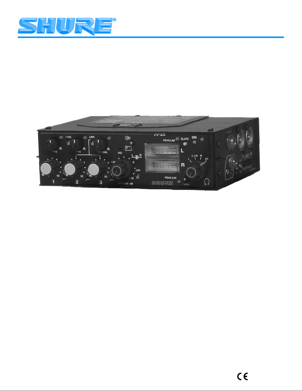
Model FP33 User Guide
STEREO ENG MIXER
2000, Shure Incorporated
27A8500 (TC)
Printed in U.S.A.
Page 2

TABLE OF CONTENTS
ENGLISH
GENERAL 1
FRONT PANEL CONTROLS AND INDICATORS (FIGURE 1) 2. . . . . . . . .
INPUT PANEL CONNECTORS AND CONTROLS (FIGURE 2) 4. . . . . . . .
OUTPUT PANEL CONNECTORS AND CONTROLS (FIGURE 3) 4. . . . . .
INTERNAL SWITCHES AND CONTROLS (FIGURE 4) 5. . . . . . . . . . . . .
INTERNAL SWITCHES AND CONTROLS (CONT.) 6. . . . . . . . . . . . . . .
POWERING THE FP33 MIXER 6. . . . . . . . . . . . . . . . . . . . . . . . . . . . .
BATTERY LIFE 6. . . . . . . . . . . . . . . . . . . . . . . . . . . . . . . . . . . . . . . .
MIXER SETUP 7. . . . . . . . . . . . . . . . . . . . . . . . . . . . . . . . . . . . . . . .
OPERATION 7. . . . . . . . . . . . . . . . . . . . . . . . . . . . . . . . . . . . . . . . .
CONNECTING FP33 TRANSFORMER
USER ADJUSTMENTS 8. . . . . . . . . . . . . . . . . . . . . . . . . . . . . . . . . .
INTERNAL MODIFIABLE FUNCTIONS 8. . . . . . . . . . . . . . . . . . . . . . . .
SPECIFICATIONS 10. . . . . . . . . . . . . . . . . . . . . . . . . . . . . . . . . . . . . .
FURNISHED ACCESSORIES 10. . . . . . . . . . . . . . . . . . . . . . . . . . . . . .
STATEMENT OF CONFORMITY 11. . . . . . . . . . . . . . . . . . . . . . . . . . . .
INFORMATION TO USER 11. . . . . . . . . . . . . . . . . . . . . . . . . . . . . . . .
. . . . . . . . . . . . . . . . . . . . . . . . . . . . . . . . . . . . . . . . . . .
BALANCED
OUTPUTS TO TELEPHONE LINES 7. . . . . . . . . . . . .
Page 3

ENGLISH
GENERAL
The Shure F P33 is a t hree-input, t wo-output p ortable stereo mixer d esigned f or p rofessional e lectronic n ews g athering (ENG), electronic field production (EFP), and on-location film production. The FP33 mixer sets a new standard
for portable m ixer p erformance a nd f eatures. A n e xceptionally low-noise d esign m akes t he F P33 i deal f or u se w ith d igital transmission links or digital video and audio recording
media, including DAT. Lightweight, compact, and rugged,
the FP 33 i s d esigned t o w ithstand t he m ost d emanding f ield
production conditions.
All types of dynamic and condenser microphones may
be used with the FP33. The mixer provides 48 V phantom,
12 V phantom, and 12 V T (A-B) power for operating condenser microphones. It will operate for at least 8 hours on
two 9 V alkaline batteries. An external 12–30 Vdc power
source, such as a Shure PS20 or PS20E ac adapter, may
also be used.
Features
• Exceptionally quiet design, suitable for use with DAT
and other digital formats
• Extended frequency response of 20 Hz–20 kHz
• Dynamic range greater than 100 dB
• Transformer balanced inputs and outputs for superior
rejection of RFI and electromagnetic hum
• Three selectable mic/line inputs
• Two selectable mic/line outputs
• Wide range input gain controls handle hot signal levels
without attenuators
• 48 V phantom, 12 V phantom, and 12 V T (A-B) microphone power
• Pop-up pan pots
• Link switch gangs inputs 2 and 3 to control a stereo mi-
crophone
• Switchable low-cut filters on each input
• Bi-color LED signal presence and peak indicator for
each input
• Professional VU meters with selectable timed or
toggled backlighting
• Dual clutched Master gain control for simultaneous or
separate adjustment of output levels
ENGLISH
• Precision, conductive plastic, sealed rotary input potentiometers
• Bi-color LED limiter and peak indicator for each output
• Two linkable output peak limiters with adjustable
thresholds and release times
• Slate microphone and slate tone with selectable func tions
• Isolated two-way talk-back using Monitor In and modified Slate Mic/Tape Out jack
• High tolerance 3.5 mm jacks for stereo Tape Out and
Monitor In
• 1 kHz tone oscillator
• Mix bus jack and cable to link FP33 or FP32A mixers
• Headphone monitor mode switch to select L, L+R
(Mono), R, or Stereo
• Internal headphone level adjustments to balance post–
master audio levels and Monitor In levels at the headphone output
• Selectable M/S decoding c ircuit for headphone m onitor .
• Mixer/Monitor In switch (locking and momentary)
• Internal Monitor defeat switch for split-feed headphone
operation
• Headphone volume control
• 1/4 in. and 3.5 mm jacks for stereo headphone outputs.
• Customized operation via internal DIP switches, trim
pots, slide switches, and optional jumpers
• Regulated voltage rails (±15 Vdc) provide exceptional
headroom
• Bi-color power On/Off LED
• Battery check switch and low battery warning LED
• Non-polarized external power jack
• External power operating range of 12 to 30 Vdc
• Soft-touch, color coded control knobs with raised posi-
tion indicators
• Metal XLR input and output connectors
• Rugged, plated metal chassis
• Operates for 8 hours on two 9 V alkaline batteries
• Includes carrying c ase, s houlder s trap, a nd m ix b us c able
• Designed and manufactured in U.S.A.
1
Page 4
ENGLISH
Á
ÁÁÁÁ
ÁÁ
Á
Á
ÁÁÁÁ
Á
ÁÁ
ÁÁÁÁÁÁ
Á
ÁÁ
Á
Á
ÁÁÁÁÁÁÁÁÁÁÁ
Á
ÁÁÁ
ÁÁÁÁÁÁÁÁÁÁÁÁÁÁÁ
Á
ENGLISH
2
1
4
3
5
6
7
8 9 10
12
7
100
LINK
RLRLRL
PAN/BALPANPAN
3
MIC
-20
7
100
MASTER2
3
13
R
L
0
LIM
+15
dB
14 15 16
1 kHz
3
3
7
100
1
11
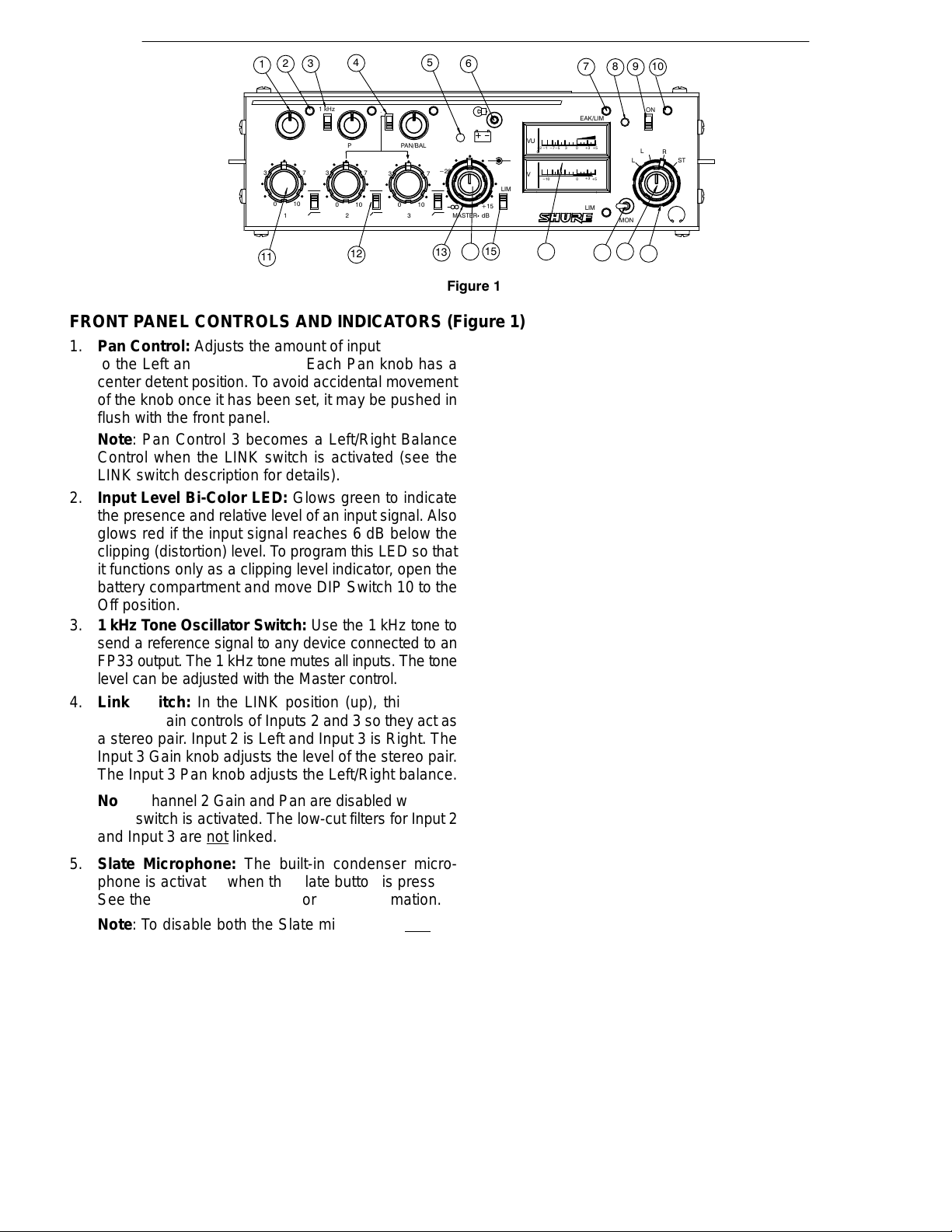
Figure 1
FRONT PANEL CONTROLS AND INDICATORS (Figure 1)
1. Pan Control: Adjusts the amount of input signal sent
to the Left and Right outputs. Each Pan knob has a
center detent position. To avoid accidental movement
of the knob once it has been set, it may be pushed in
flush with the front panel.
Note: Pan Control 3 becomes a Left/Right Balance
Control when the LINK switch is activated (see the
LINK switch description for details).
2. Input Level Bi-Color LED: Glows green to indicate
the presence and relative level of an input signal. Also
glows red if the input signal reaches 6 dB below the
clipping (distortion) level. To program this LED so that
it functions only as a clipping level indicator, open the
battery compartment and move DIP Switch 10 to the
Off position.
3. 1 kHz Tone Oscillator Switch: Use the 1 kHz tone to
send a reference signal to any device connected to an
FP33 output. The 1 kHz t one m utes all inputs. The t one
level can be adjusted with the Master control.
4. Link Switch: In the LINK position (up), this switch
links the gain controls of Inputs 2 and 3 so they act as
a stereo pair. Input 2 is Left and Input 3 is Right. The
Input 3 Gain knob adjusts the level of the stereo pair.
The Input 3 Pan knob adjusts the Left/Right balance.
Note: Channel 2 Gain and Pan are disabled when the
LINK switch is activated. The low-cut filters for Input 2
and Input 3 are not
linked.
5. Slate Microphone: The built-in condenser microphone is activated when the Slate button is pressed.
See the Slate Button section for more information.
Note: To disable both the Slate microphone and
the
Slate tone, set internal DIP Switches 5, 6, and 7 to Of f.
The Slate microphone may also be modified to act as
a talk-back microphone for communications. Refer to
the Internal Modifiable Functions section for details.
6. Meter Lamp/Battery Check Switch: The Meter
Lamp function is activated by momentarily pushing
this switch upward. This function can be internally preset for timed or toggled deactivation. See the table in
the Internal Switches and Controls section for details.
The Battery Check function is activated by momentarily pushing this switch downward. The status of the
two 9 V batteries is indicated on the VU meter. When
the mixer is using an external dc supply and no batter-
7. Output Peak/Limiter Bi-Color LED: Glows red for
8. Slate Button: Activates a 400 Hz Slate Tone for one
9. Power On/Off Switch: Turns the mixer on and off.
10. Power On LED: Monitors the higher of the internal or
2
FP33
PEAK/LIM
VU
VU
BATT
-7
-2
-10
0
-10
-20
+5
-3-5
0
+3
-7
-
+5+30
-3
5
PEAK/LIM
17
SLATE
L
R
MON
18
ON
L+R
R
ST
L
19
ies, the Battery Check indicates the status of the external operating voltage. When the mixer is using 9 V
batteries
and
an external dc supply , the Battery Check
indicates the status of the higher voltage source. A low
battery condition also is indicated when the Power On
LED changes to red and flashes at a slower rate. For
instructions on modifying the FP33 to allow only internal batteries or external power to be monitored at the
VU meter, see Internal Modifiable Functions.
Note: The audio signal is not interrupted when the
Battery Check switch is activated.
the individual Left and Right Channels when the output signal reaches a factory preset peak level of +17
dBm. This peak level is user-adjustable from 0 dBm to
+17 dBm. (See the Peak LED Adjustment instructions.) If the Limiter is switched on, each LED glows
green to indicate Limiter operation. The LED will still
glow red if the preset peak level is reached before the
Limiter activation point is reached.
second and also activates the Slate Microphone. The
Slate Microphone remains on while the button is depressed. The Slate signal (Tone and Mic) appears at
the Left and Right outputs to identify the beginning of
a take. If desired, the Slate features can be modified
as follows: disable the Slate Tone; insert the Slate signal pre-Master control; or insert the Slate signal postMaster control. See the Internal DIP Switches table for
instructions.
Note: To disable both the Slate microphone
and
the
Slate tone, set internal DIP Switches 5, 6, and 7 to Of f.
The mixer is on when this switch is in the “up” position.
external voltage sources. Flashes green to indicate
power is on and voltage is greater than 12 Vdc.
Flashes red and slower to indicate low power (12 Vdc
or less).
When this LED monitors the internal battery level, it
glows red typically when 30 minutes of battery power
remain. Refer to the Internal Battery Life section. For
instructions on modifying the FP33 to allow only internal batteries or external power to be monitored at
Page 5

ENGLISH
the VU meter, refer to the Internal Modifiable Functions section.
11. Input Gain Control: Adjusts the gain level of each input channel. Rotating the knob counterclockwise reduces the gain and raises the input clipping point. Use
a low control setting to handle “hotter” input signals
without distortion. With the FP33 input circuit, microphones with a “hot” output may be used without an inline pad (attenuator). For best performance, adjust
each Input Gain control so the associated Input Level
LED illuminates red only on the loudest signal peaks.
12. Input Low-Cut Filter Switch: Provides low-frequency roll-off to reduce wind noise and rumble. When using the filter, the frequency response is down 6 dB at
150 Hz. The roll-off slope is 6 dB per octave.
13. Master Gain—Right Channel Output: The outer
ring controls the Right channel output gain. The dualclutched control lets the Right and Left outputs be adjusted individually. Set it to “0 dB” for unity gain.
14. Master Gain—Left Channel Output: The inner knob
controls the Left channel output gain. The dualclutched control lets the Right and Left outputs be adjusted individually. Set it to “0 dB” for unity gain.
Note: The 1 kHz tone oscillator level is set by the
Master Level controls. To calibrate other devices,
adjust the Master Level controls for a 0 VU response.
15. Output Peak Limiter Switch: Activates two fast-acting, peak-responding limiters, one for each output
channel. Limiters help prevent overload distortion
from unexpected loud input signals. The limiter activation is indicated by the Output Peak/Limiter LEDs,
which illuminate green.
The limiters may be changed to: operate independently; be linked as a stereo pair; activate at thresholds from 0 dBm to +15 dBm; and have release time
constants of 0.1 second or 1 second. See the Internal
ENGLISH
DIP Switches and Limiter Threshold Adjustment for
instructions.
16. Left/Right Channel Output Level Meters: 0 VU is
preset at a +4 dBm output level. This may be recalibrated for e ach m eter b y a n i nternal t rim p otentiometer .
See the VU Meter Adjustment paragraph for instructions.
Note: Mechanical meters are used because LCD meters do not operate properly in cold weather; fluorescent meters drain batteries too quickly; and LED meters are difficult to see in sunlight.
17. Monitor Input Switch: In the center position, this
switch sends the post-master audio to the headphone
output. In the left (locking ) or right (momentary) position, it sends the audio signal from the Monitor In jack
to the headphone output.
18. Headphone Gain Control (Inner Knob): Adjusts the
headphone volume level.
WARNING: The headphone circuit is capable of
producing high volume levels that can damage the
user’s hearing. Make sure the headphone volume
setting is low (fully CCW) before putting on the
headphones.
19. Headphone Monitor Mode Switch (Outer Ring):
The user c an m onitor t he F P33 o utput a s: S tereo; R ight
channel only; M ono ( Left + R ight); o r Left channel o nly.
Note: This switch also affects the Monitor In signal.
When using a stereo MS microphone, such as the
Shure VP88, the user may wish to pass the mic signal
through the FP33 as separate Mid and Side signals,
yet hear decoded stereo in the headphones. Using the
Headphone MS Matrix, the user can monitor the FP33
output as: Discrete (Mid and Side); Side only, Stereo
(decoded MS), or Mono (Mid only). Refer to the Internal DIP Switch table for instructions on activating the
Headphone MS Matrix.
3
Page 6

ENGLISH
Á
ÁÁÁÁÁÁÁÁÁÁÁÁ
ÁÁÁÁÁÁÁÁÁÁÁÁÁÁ
Á
Á
Á
Á
Á
Á
Á
Á
Á
Á
Á
ÁÁÁÁ
Á
ÁÁÁÁÁÁÁ
Á
Á
Á
Á
Á
Á
Á
Á
Á
Á
Á
Á
ÁÁ
Á
1
IN
21
11111
MIC LINE
3
MIC LINELINEMIC
2
Figure 2
INPUT PANEL CONNECTORS AND CONTROLS (Figure 2)
1. Channel Inputs: The three female XLR inputs are
transformer balanced for superior rejection of hum,
RFI, and other interference. Each input can provide
48 V or 12 V phantom power (for condenser microphones); 12 V T (A-B) power (for condenser microphones); or no power (for dynamic microphones). See
the Internal Switches and Controls section.
1
MIX BUS
2. Mic/Line Level Input Switch: Selects Microphone or
2
ENGLISH
Line to match the incoming signal level. The Mic signal
level is typically 0.1–3 mV, and the Line signal level is
typically 0.1–3.0 V. In the Line level position, phantom
and T power are disconnected from the input.
3
45
MON
TAPE
IN
OUT
6
Figure 3
OUTPUT P ANEL CONNECTORS AND CONTROLS (Figure 3)
1. Mix Bus Jack: Allows an FP33 to be c onnected t o a n
additional FP33 or FP32A mixer. A mix bus cable is
supplied with every FP33. The Mix Bus connection is
”two-way” and pre-Master. When two mixers are connected via the Mix Bus, all six inputs appear at both
mixers’ outputs. The M aster G ain control of e ither m ixer can be adjusted without affecting the output of the
other. T his p rovides t he e quivalent o f a s ix-input s tereo
mixer with two separate Master output sections.
Note: The output level of both mixers will drop by 6 dB
when they are connected via the Mix Bus. Increase
the Master Gain to compensate for this.
2. Main Output: The two male XLR outputs are transformer balanced and may be switched to Mic or Line
Level. The Line Level output can be modified to a true
600 Ω. See the Internal Modifiable Functions section.
3. Headphones Outputs: A stereo 1/4 in. phone jack
and a stereo 3.5 mm mini-phone jack may be used
separately, simultaneously, or as auxiliary feeds to
other equipment.
4. Monitor In Jack: Designed to accept stereo line-level
signals. This 3.5 mm jack provides a “tape return” input or a communications channel input. This signal
appears only in the FP33 headphone circuit. Activating the front panel Monitor In switch routes the Monitor
5. Tape Output Jack: A stereo 3.5 mm mini-phone jack
6. Mic/Line Level Output Switch: Selects Mic or Line
7. 12–30 Vdc In Jack (External Power): This accepts
OUT
RL
LINEMICLINEMIC
12-30 VDC IN
7
In signal to the headphones. Program audio is
heard
in the headphones when this switch is on.
not
Note: A “split-feed” (FP33 a udio in one ear a nd M onitor
In audio in the other) can be accomplished via internal
DIP Switches 4 a nd 5 . A lso, a n i nternal m odification w ill
allow attenuated FP33 audio to be heard in the headphones even when the Monitor In switch is activated.
Refer to the Internal Modifiable Functions section.
(auxiliary level) to feed a cassette recorder, DAT machine, or semi-pro video recorder. This output can be
modified to provide a m ono ( L+R) s ignal; p rovide a n u nbalanced line level or mic level output; provide an isolated output containing only the Slate mic and Slate
tone. Refer to the I nternal M odifiable F unctions s ection.
Level to match the input level of the d evice c onnected
to the FP33 output. The Mic signal level is typically
0.1–3 mV; the Line signal level is typically 0.1–3 V.
a non-polarized coaxial plug from a 12 to 30 Vdc external power supply. The external supply must have a
negative ground or a floating ground. A Shure PS20
or PS20E ac adapter, an automotive battery, or a rechargeable belt pack are all suitable power supplies.
4
Page 7

ENGLISH
Á
Á
Á
ÁÁÁ ÁÁÁÁÁÁÁ
ÁÁÁÁÁÁÁÁÁÁÁÁÁÁ
Á
ÁÁÁ
Á
ÁÁ
ÁÁ
ÁÁÁ
Á
ÁÁ
ÁÁ
Á
Á
ÁÁ
ÁÁ
Á
Á
Figure 4
INTERNAL SWITCHES AND CONTROLS (NO TAG)
1. Battery Compartment: Holds two 9 V alkaline batteries. Two fresh batteries will power the unit for about
eight hours under normal conditions.
2. Microphone Power Selection Switch: Position this
slide switch to match the type of input power desired:
Top Position 12V T (A-B):
with certain Sennheiser and Schoeps microphones.
FP33
Input
12
3
180 Ω
I
I
180 Ω
I = Microphone Supply Current
Figure 5
Middle Position (Dynamic):
2, or 3. Used with dynamic microphones or condenser
microphones that have internal batteries.
Bottom Position (Phantom):
ternal DIP switch 11 selects 12 volts or 48 volts. 48 V
phantom power drains the batteries faster than 12 V
phantom power. Used with all condenser microphones that do not require T power.
FP33 Input
1
3
R
2
R
I
R = 680 Ω for 12 V
R = 6.8 kΩ for 48 V
Figure 6
Caution: Balanced dynamic microphones will not be
damaged by phantom power but may be damaged by
T power.
Refer to Figure 5. Used
Balanced Audio
to Microphone
Preamp
12 V
Power
(A-B)
No dc power on pins 1,
Refer to Figure 6. In-
I = Microphone Supply Current
Phantom
I
I
Phantom
Balanced Audio
to Microphone
Preamp
12–48 V
Phantom
Power
+
–
+
–
–
ENGLISH
12
2
1
3
4
5
6
7
8
9
10
11
3. Fuse and Spare Fuse: Designed to protect the FP33
from damage that may result from using a c ommon e xternal dc power supply with other electronic devices.
Caution: Damage may result when using a common
external dc power supply with other electronic devices
that are “positive ground.” Separate power supplies a re
recommended.
4.
Level R Potentiometer: Attenuates the level of the
FP33 right channel program audio that is fed to the
headphone/monitor circuit. This does not affect the
Monitor In levels at the headphone output.
5. Peak LED R Potentiometer: Adjusts the Right Peak
LED to light at a preset output level. The factory setting
is +17 dBm. The user adjustment range is 0 dBm to
+17 dBm. See the Peak LED Adjustment paragraph.
6. Peak LED L Potentiometer: Adjusts the Left Peak
LED to l ight a t a p reset o utput l evel. T he f actory s etting
is +17 dBm. The user adjustment range is 0 dBm to
+17 dBm. See the Peak LED Adjustment paragraph.
7. Lim Adj R Potentiometer: Adjusts the Right limiter to
operate at a preset output level. The factory setting is
+15 dBm. The user adjustment range is 0 to +15 dBm.
See the Limiter Threshold Adjustment paragraph.
8. Lim Adj L P otentiometer: Adjusts the Left limiter t o o perate at a preset output level. The factory setting is
+15 dBm. The user adjustment range is 0 to +15 dBm.
See the Limiter Threshold Adjustment paragraph.
Level L Potentiometer: Attenuates the level of the
9.
FP33 left channel p rogram a udio t hat i s f ed t o t he h eadphone/monitor circuit. This does not affect the Monitor
In levels at the headphone output.
10. Meter Adj R P otentiometer: Adjusts the Right meter t o
indicate 0 VU a t a p reset o utput l evel. T he factory setting
is +4 dBm. T he u ser a djustment r ange i s 0 to +16 dBm.
Refer to the VU Meter Adjustment paragraph.
11. Meter Adj L Potentiometer: Adjusts the Left meter to
indicate 0 VU at a preset output level. The factory s etting is +4 dBm. The user adjustment range is 0 dBm to
+16 dBm. See the VU Meter Adjustment paragraph.
12. Internal DIP Switches: 12 internal DIP switches allow the user to customize operation. The function of
each DIP switch is listed in the table on the following
page.
5
Page 8

ENGLISH
INTERNAL SWITCHES AND CONTROLS (Cont.)
Note: Bold type indicates the Factory setting.
DIP SWITCH
1 LIM LINK ON
POSITION FUNCTION
Left and Right limiters act in tandem. If limiter thresholds are set differently, limiter action
is determined by the lower threshold setting.
ENGLISH
OFF
2 LIM RELEASE R SHORT
LONG
3 LIM RELEASE L SHORT
LONG
4 MON DEFEAT R OFF
ON
5 MON DEFEAT L OFF
ON
6 PRE-MAST SLATE ON
OFF
7 POST-MAST SLATE ON
OFF
8 SLATE TONE ON
OFF
9 METER LAMP TOGGLED
TIMED
10 PRESENCE LEDs ON
OFF
11 12 V OR 48 V PHANTOM 12V
Left and Right limiters act independently.
Right limiter release time constant is 0.1 second. Use for speech.
Right limiter release time constant is 1 second. Use for music.
Left limiter release time constant is 0.1 second. Use for speech.
Left limiter release time constant is 1 second. Use for music.
When front panel Monitor switch is activated, Monitor In signal is heard in Right head-
phone.
When front panel Monitor switch is activated, Monitor In signal is not
phone. Mixer audio remains in Right headphone.
When front panel Monitor switch is activated, Monitor In signal is heard in Left headphone.
When front panel Monitor switch is activated
phone. Mixer audio remains in Left headphone.
Inserts slate tone and slate microphone into circuit before the Master gain control (pre–
master). Slate level is controlled by Master.
Removes slate tone/slate microphone from pre-master cIrcuit.
Inserts slate tone and slate microphone into FP33 circuit after the Master gain control
(post-master). Slate level not is controlled by Master.
Removes slate tone and slate microphone from FP33 post-master circuit.
Slate tone (400 Hz) sounds for one second when front panel slate button is pushed. Slate
microphone also activates.
Slate tone does not sound when slate button is pushed. Slate microphone does activate.
Lamp turns on/off when front panel lamp switch is toggled. Automatic timed turnoff of lamp
will not occur.
Lamp turns on/off when front panel lamp switch is activated. If not manually switched off,
lamp will automatically turn off after 10 seconds to conserve battery life.
Input LEDs illuminate green to indicate signal presence and relative level.
Input LEDs do not
fore clipping.
Provides 12 Vdc phantom power if selected for channel input.
illuminate green. Input LEDs will still illuminate red to indicate 6 dB be-
, Monitor In signal is not heard in Left head-
heard in Right head-
12 MS MATRIX FOR
HEADPHONES
48V
ON
OFF
Provides 48 Vdc phantom power if selected for channel input.
Inserts MS decoding matrix into headphone circuit. User can monitor in stereo while allow-
ing separate Mic and Side signals to pass through the FP33.
Removes MS decoding matrix from headphone circuit.
POWERING THE FP33 MIXER
The FP33 c an b e p owered b y a 12–30 Vdc external p ower
supply while preserving the life of the internal batteries.
External Power Supplied Internal Batteries
11.4 Vdc to 30 Vdc OFF (200 µA current at 18 V)
<11.4 Vdc ON (Full power for the FP33 is sup-
plied by the higher voltage source)
BATTERY LIFE
The FP33 is designed for low current consumption.
Under typical conditions (+4 dBm into 6 00 Ω i n continuous
use and no phantom–powered microphones, meter illumination, or headphones in use), and with two fresh 9 volt
alkaline batteries , the FP33 will operate for about eight
hours before t he P ower L ED f lashes. A t t h is p o in t, a bout 3 0
minutes of battery life remain. If more mixer features are
used, battery life will decrease accordingly (see table).
Mixer Operation Battery
(A) Idle, no signal 41 9
(B) As in (A) with +4 dBm continuous
output
(C) As in (B) with three Shure SM81 mi-
crophones at 12 V phantom power
(D) As in (B) with three Shure SM81 mi-
crophones at 48 V phantom power
(E) As in (B) with 63 Ω headphones
driven moderately loud (Sony MDRV6)
(F) As in (B) with meter illumination
continuously on
*Until Power LED begins to flash, and allowing 30 minutes to replace
batteries.
Current
(mA)
46 7.8
50 7.5
57 6.0
50 6.9
63 5.5
Note: Momentary use of headphones or meter illumination will not appreciably affect battery life.
6
Battery
Life
(hours)*
Page 9

ENGLISH
MIXER SETUP
Prepare the FP33 stereo mixer for operation as follows:
1. For internal battery operation, lift the latch on the top
panel and o pen t he b attery c ompartment. I nstall t wo 9 V
alkaline batteries, making sure the polarity (+/–) is correct. Select t he p roper m icrophone p owering f or e ach i nput via the slide switches. Close the compartment door
and secure t he l atch. F or e xternal p ower o peration, p lug
a 12 to 30 Vdc source into the External Power jack on
the right side panel of the FP33.
2. Connect the microphone, wireless receiver, or other
audio source to the desired Input Channel connector
on the left side panel.
When using a stereo microphone, such as the
Note:
Shure VP88, connect it to Channels 2 and 3. Use the
front panel LINK s witch t o m ake Inputs 2 a nd 3 a s tereo
pair. I n t he L INK m ode: C hannel 2 = L eft or Mid; C hannel 3 = Right or Side.
3. Position each Mic/Line Input switch based on the level
of the incoming source.
4. Connect the camcorder, DAT machine, wireless trans-
mitter, o r o ther equipment t o the L eft a nd R ight O utput
XLR connectors on the right side panel of the FP33.
5. Position each Mic/Line Output switch based on the in-
put level requirements of the equipment connected to
the FP33 outputs.
6. If a “tape return” or Monitor In feed into the FP33 is re-
quired, connect a 3.5 mm stereo male plug into the
Mon In connector on the right side panel. The signal
on this plug typically comes from the audio output of
whatever device is being fed by the FP33. See
NO T AG.
RIGHT AUDIO
LEFT AUDIO
RIGHT AUDIO
ENGLISH
OPERATION
To operate the FP33 stereo mixer, proceed as follows:
1. Apply power to the mixer by sliding the On/Off switch
to the On position. The green P ower O n L ED w ill f lash
at a constant rate to i ndicate t hat t he m ixer i s t urned o n.
2. Check the mixer power status by moving the front panel
Battery Check switch downward toward the battery icon.
The needle on the top VU meter will swing to the sloped
red BATT indication. If the needle falls below the red
BA TT indication, the unit is not receiving adequate power
from the internal 9 V batteries or the external dc supply.
3. Move the front panel MON toggle switch to the center
position to route FP33 audio to the headphones. Setting this switch to the left or right routes the Monitor In
audio to the headphones. The right position is momentary, for quickly checking the Monitor In audio.
4. Slide the LIM switch to the desired position: Up to turn
the output limiters on, Down to turn them off. Keep the
limiters on to protect against output overload.
5. Position the Low-Cut Filter switches for each Input: Up
for low-cut off, Down for low-cut on.
6. For an initial gain setting, rotate the Master Gain knob
to “0 dB” (2 o’clock). This provides unity gain for the
output stages. Note: t he M aster G ain c an b e a djusted
during mixer operation as input levels vary.
7. Activate the 1 kHz tone oscillator by sliding the switch
to the On (up) position. Use the tone to set the input
level control of the device following the FP33. Once
the input level of the following device is set, slide the
switch to the Off (down) position to turn off the tone.
Note: The tone oscillator of the FP33 is not used to set
the controls of the FP33. Those are set according to
the input signals coming into the FP33.
8. Rotate the Headphone Monitor Mode knob to the ST
(Stereo) position.
9. Put on headphones and carefully a djust t he h eadphone
volume control.
GROUND
GROUND
LEFT AUDIO
Figure 7
7. If an unbalanced output feed is desired, connect a
3.5 mm stereo male plug into the Tape Out connector
on the right side panel. This would typically feed a cassette recorder or a DAT machine. Refer to NO TAG.
8. Plug headphones into the stereo 1/4 in. phone or
3.5 mm mini–phone jacks on the right side panel.
Note: The two headphone output connectors may be
used separately, simultaneously , o r a s auxiliary feeds
to other equipment.
9. To interconnect two mixers, plug the supplied Mix Bus
cable into the Mix Bus connectors of both mixers.
Note: When two FP33 or FP32A mixers are interconnected via t he M ix B us, t he M aster G ain o n e ither m ixer
can be a djusted w ithout a f fecting t he o ther m ixer’s output level. This provides the equivalent of a six–input
stereo mixer w ith t wo s eparate M aster o utput s ections.
10. Set the Master Gain, Headphone Volume, and all Input Gains fully counterclockwise (off).
WARNING: The headphone circuit is capable of
producing loud levels that can damage the user’s
hearing. Be sure the headphone volume setting is
low (fully CCW) before putting on the headphones.
10. Adjust the Input Gain and Pan controls based on the
incoming signal levels. The Input LEDs should flicker
red only on the loudest input peaks. After these settings have been made, the Pan knobs can be pressed
flush to the front panel to avoid accidental movement.
11. Observe the output on the VU meters and adjust the
Master Gain to obtain the desired levels. Try to keep
the average levels around “0 VU.”
Note: To illuminate the VU meters, move the front
panel toggle switch up toward the light bulb symbol.
12. Press the Slate button to insert a momentary 400 Hz
Slate tone into the FP33 output for “take” identification
purposes. The FP33 mixer is now ready for use.
Note: If desired, vocally identify the “take” via the
Slate Mic while pressing the Slate button.
CONNECTING FP33 TRANSFORMER
BALANCED OUTPUTS TO TELEPHONE LINES
In the L ine p osition, t he L eft a nd R i ght X LR o utputs c an b e
used to drive dc-biased, “dialed up” telephone lines,
7
Page 10

ENGLISH
although there may be a slight increase in distortion. Use of
the limiter circuit is strongly advised, with the FP33 limiter
threshold set to +4 dBm. Modification o f t he F P33 o utput i mpedance to 600 Ω is recommended for proper fidelity. (See
the Internal Modifiable Functions section for instructions.)
When connecting the FP33 to a telephone line in the United
States, use of an FCC-Registered interface adapter between
the mixer and the telephone line is mandatory. Outside the
U.S., consult the local telecommunications authority.
USER ADJUSTMENTS
VU Meter Adjustment
To set the VU Meters to a value other than the factory
setting (0 VU = +4 dBm), proceed as follows:
1. Connect a 600 Ω load across the Left XLR output set
for Line.
2. Connect an ac voltmeter (such as the HP 400GL) in
parallel with the load.
3. Slide the 1 kHz tone oscillator switch to the On (up)
position.
4. Adjust the 1 kHz Tone Oscillator level with the Left
(inside) Master gain control until the ac voltmeter reading is at the level desired.
5. Open the battery compartment door and adjust the
Left VU Level trim pot with a screwdriver until the Left
VU Meter reads 0.
6. Repeat the above procedure for the Right Output and
the Right VU Meter.
Limiter Threshold Adjustment
To adjust the Limiter threshold to a value other than the
factory setting (+15 dBm), proceed as follows:
1. Connect a 600 Ω load and an ac voltmeter across the
Left Line output as described in steps 1 and 2 of the
VU Meter Adjustment procedure.
2. Open the battery compartment and move DIP switch
1 to the Off position (refer to the chart on the inside of
the door).
3. Slide the 1 kHz tone oscillator switch to the On (up)
position.
4. Slide the Limiter switch to the Off (down) position.
5. Adjust the Left Master gain control until the ac voltmeter reading is 2 dB above the desired output level.
6. Slide the Limiter switch to the On (LIM) position.
7. Open the battery compartment and adjust the Lim Adj
L trim pot until the level drops to the desired reading.
8. Repeat the above procedure for the Right output, using the Lim Adj R trim pot.
Peak LED Adjustment
To adjust the Peak LED threshold to a value other than
the factory setting (+17 dBm), proceed as follows:
1. Connect a 600 Ω load and an ac voltmeter across the
Left Line output as described in steps 1 and 2 of the
VU Meter Adjustment procedure.
2. Slide the 1 kHz tone oscillator switch to the On (up)
position.
3. Slide the Limiter switch to the Off (down) position.
4. Adjust the Left Master gain control until the ac voltmeter reading is at the desired peak output level.
ENGLISH
5. Open the battery compartment and turn the Peak LED
L trim pot completely clockwise.
6. Slowly adjust the trim pot counterclockwise until the
left Peak/Lim LED first illuminates red.
7. Repeat the above procedure for the right Peak/Lim
LED, using the Peak LED R trim pot.
Headphone Level Adjustments
To adjust the program level to match the audio signal
levels from a monitored source, proceed as follows:
1. Open the battery compartment and adjust the Headphone Level L a nd Headphone Level R f ul counterclockwise.
2. Connect the device to be monitored via the 3.5 mm
Monitor In jack.
3. Move the Monitor Input Switch on the front panel to the
locking position (left).
4. Adjust the monitor input level, using the headphone
gain control on the front panel.
5. Move the Monitor Input switch on the front panel to the
post-master audio position (center).
6. Adjust the post-master audio to a comparable level,
using the Headphone Level L and Headphone Level
R potentiometers.
INTERNAL MODIFIABLE FUNCTIONS
Selected internal functions of the FP33 can be modified
by the user to fit special applications. Procedures for performing these modifications are listed below.
CAUTION: Due to the complex construction and extensive use of surface-mount components, modifications to
the FP33 must be performed by a qualified service technician. Contact the Shure Service Department or your authorized Shure Service Center for further information on
these modifications.
Disassembly
1. Remove the six screws that secure the cover.
2. Slowly slide the cover backwards and unplug ribbon
cable P109.
3. Remove the three screws (marked with arrows) that
secure the upper PC board.
4. Remove the upper PC board.
5. Perform the appropriate modification procedure.
6. Reassemble the unit by doing Steps 1–4 in reverse.
Changing the Line Level Output Impedance to 600 Ω
1. Locate R674 and R668 on the bottom PC board and
remove them.
2. Locate X503 a nd X 505 o n t he b ottom P C b oard a nd s ol-
der a 470 Ω, 1/2W resistor through the holes at X503.
3. Solder a 470 Ω, 1/2W resistor through the holes at
X505.
Changing the Tape Out Jack from Stereo (tip = L;
ring = R) to Mono (tip = L+R; ring = L+R)
1. Locate X504 on the top side of the lower PC board, by
the Tape Out jack.
2. Solder a jumper through the holes at X504.
Decreasing Tape Out Level to Mic Level
1. Locate R111 2 and X511 (the top side of the bottom PC
board, by the L Out XLR connector).
8
Page 11

ENGLISH
2. Locate R11 14 and X510 (the bottom side of the bottom
PC board, by the Tape Out jack).
3. Remove R1112 and R1114.
4. Solder a jumper through the holes at X511.
5. Solder a jumper through the holes at X510.
Increasing the Tape Out Level by +10 dB
1. Locate R669 and R672 on the bottom PC board.
2. Remove these two resistors.
3. The Tape Out impedance is now 6 kΩ.
Changing the Slate Mic and the Slate Tone to Feed
Only the Tape Out Jack
This modification provides an isolated, unbalanced output for talk-back. For example, the user could talk to a
boom operator though the Slate mic. The Monitor In function could be used to hear the boom operator’s response.
1. Locate and remove R663, R669, R670, R672, R673,
and R765 from the bottom PC board.
2. Solder a jumper through the holes at X504 (behind the
Tape Out jack).
3. Solder one end of an insulated jumper into the hole at
X600 (about 40 mm [1.5 in.] behind the Tape Out jack).
4. Solder the other end o f this j umper to t he jumper a t X504.
5. Set the Pre-Mast Slate DIP switch (#6) to On.
6. Set the Post-Mast Slate DIP switch (#7) to Off.
7. The nominal Tape Out level i s n ow – 10 dBV (aux l evel).
The M odified Tape Out c ontains
only
t he S late t one a nd
Slate microphone. The Slate tone and Slate microphone are removed from the main outputs.
Providing Mixer Audio in the Headphones when the
Monitor Switch is Activated
This modification allows the user to listen to the monitor
input signal and attenuated mixer audio simultaneously.
1. Locate X501 and X502 on the bottom PC board.
2. Determine the amount of a ttenuation d esired f or m ixer
audio, using the following table.
Mixer Audio Attenuation Required Resistor
Impedance
Less than 10 dB Less than 150 kΩ
10 dB 150 kΩ
15 dB 300 kΩ
Greater than 15 dB Greater than 300 kΩ
3. Solder a 1/8W or 1/4W resistor through the holes at
X501.
4. Solder a 1/8W or 1/4W resistor through the holes at
X502.
5. Activate the Monitor In switch. FP33 audio will be attenuated by the predetermined level.
Decreasing the Low-Cut Filter Corner Frequency
(3 dB down point)
1. Calculate a new capacitor value for the lower low-cut
corner frequency. Use the following formula:
C in µF= (85/frequency) - .33
Example for 200 Hz corner frequency
85/200 = .43
.43-.33 = .1 µF
For a 200 Hz corner frequency, use a 0.1 µF capacitor.
ENGLISH
Note: The capacitor must be a ceramic or film type,
non-polarized, with a 16 V or higher rating.
2. For Input 1, locate X811 and X812. Solder the new capacitor between these points.
3. For Input 2, locate X813 and X814. Solder the new capacitor between these points. A lso locate X 815 and X 816
on the bottom board, just behind the input gain controls.
Solder another new capacitor between these points.
4. For Input 3, locate X809 and X810 on the bottom
board, just behind the input gain controls. Solder the
new capacitor between these points.
5. To raise the corner frequency higher than the factory
preset of 260 Hz, contact the Shure Technical Application Group at (847) 866-2525.
Slowing Down Output Level Meters to Approximate
“True VU” Ballistics
1. Locate empty pads C302 and C303 on the top PC
board, behind the power switch.
2. Solder a 15 0 µF x 6.3 V electrolytic capacitor in C302.
The + lead must face the meters.
3. Solder a 15 0 µF x 6.3 V electrolytic capacitor in C303.
The + lead must face the meters.
4. To slow the meter response even more, further increase the µF value of C302 and C303.
Changing Battery Indicators to Monitor Internal or
External Power
The following modifications allow only the internal batteries or the external power supply to be monitored at the
VU meter.
Modification: To monitor external
power only
Procedure: Remove R492 Remove R490
To monitor internal
battery power only
The following modifications allow the Red/Green Power
LED to indicate low voltage status for only the internal battery or the external power supply.
Modification: To indicate low ex-
ternal power only
Procedure: Remove R493 Remove R491
To indicate low internal battery power only
Other Available Modifications
• Changing VU Meter S cale f or B attery Voltage Indication
• Converting FP32 to FP32A or FP33 Mix Bus
• Increasing Output Level of Slate Mic
• Power LED Red Flashing Point
• Reduction of Headphone Circuit Output Impedance
• Single Output Level Control
• XLR Connector Change from Female to Male
For further information about these modifications, call
the Shure Technical Application Group at (847) 866–2525.
9
Page 12

ENGLISH
SPECIFICATIONS
Measurement conditions, unless otherwise specified: Op-
erating Voltage: 18 Vdc
Full gain
1 kHz input signal.
Output terminations: Line 600
Tape Out 50 k
Ω,
Headphone
200 Ω.
Frequency Response
20 to 20,000 Hz ±2.0 dB (channel controls centered).
Voltage Gain
Input Line Mic Headphone Tape
Low-Z
Mic
(150 Ω)
Line 28 dB –22 dB 39 dB 16 dB
Monitor ––
78 dB 28 dB 89 dB 66 dB
––
Inputs
IMPEDANCE
Input Designed for
Use with
Mic 19 to 600 Ω 1 kΩ –10 dBV
Line ≤10 kΩ 50 kΩ +36 dBV
Monitor ≤ 1 kΩ 10 kΩ +21 dBV
Actual
(Internal)
Outputs
IMPEDANCE
Input Designed for
Mic Low-Z
Line 600 Ω 150 Ω +18 dBm
Tape >10 kΩ 2.2 kΩ +3 dBV
Headphones 8 to 200 Ω 300 Ω +11 dBV
Use with
inputs
(Internal)
Total Harmonic Distortion
0.25% THD at +4 dBm output, 50 to 20,000 Hz.
Equivalent Input Noise
–127 dBV with 150 Ω source, 20 to 20,000 Hz.
Output Noise
Master level fully CCW: ≤ –100 dBV, 20 to 20,000 Hz.
Master level fully CW: ≤ –80 dBV, 20 to 20,000 Hz.
Common Mode Rejection Ratio
65 dB at 100 Hz, –20 dBV input.
Polarity
Mic/Line In to Mic/Line Out Non-Inverting
Mic/Line In to Headphones Non-Inverting
Mic/Line In to Tape Out Non-Inverting
Mic/Line to Mix Bus Inverting
Monitor In to Headphones Non-Inverting
Ω;
Mic 150
11 dB ––
Input Clip
Level
Actual
1 Ω –31 dBV
Output Clip
Level
Ω;
ENGLISH
Overload and Shorting
Shorted outputs, even for prolonged periods, cause no
damage. Microphone inputs of up to 3 Vrms cause no
damage. The Line and monitor inputs can withstand signals of up to 30 Vrms.
Input Channel Bi-Color LEDs
Green: Signal presence; visual indication of mix level.
Red: 6 dB below clipping level.
Output Peak/Limiter Bi-Color LEDs
Green: Output being limited by 1 dB or more.
Red: Output peak threshold reached; factory set at
+17 dBm; user adjustable from 0 to 17 dBm.
Output Clipping Level
≥ +18 dBm at line output into 600 Ω.
Low–Cut Filters
6 dB down at 150 Hz; 6 dB/octave slope.
Pan Attenuation Level
45 dB.
Tone Oscillator
1 kHz ±10%.
Slate Tone Oscillator
400 Hz ±10%.
Limiter
Threshold: Adjustable; 0 dBm to +15 dBm.
Attack Time: 1 ms.
Release Time Constant: Selectable; 100 ms or 1 s.
Indicator: Green when limiting by 1 dB or more.
Microphone Power
12 V Phantom: 12 V through matched 680 Ω.
48 V Phantom : 48 V through matched 6.8 kΩ.
12 V T (A–B):12 V through matched 180 Ω.
Mixer Power
Internal: Two 9 V alkaline batteries.
External: 12–30 Vdc to dc In jack; non–polarized.
Current Drain: Approximately 41 mA (idle) at 18 V.
Battery Life: 8 hours minimum, typical.
Temperature Range
Operating: 0° to 60° C (32° to 140° F).
Storage: –40° to 85° C (–40° to 185° F).
Overall Dimensions (H x W x D)
58 mm x 184 mm x 161 mm (7–1/4 x 6–3/8 x 2–1/4 in.).
Net Weight (without batteries)
1.6 kg (3.5 lbs).
FURNISHED ACCESSORIES
Carrying Case 26A19. . . . . . . . . . . . . . . . . . . . . . . . . . . . .
To wrap the carrying case around the FP33 mixer, refer
to the assembly instructions supplied.
Shoulder Strap 95A8508. . . . . . . . . . . . . . . . . . . . . . . . . .
Connect the strap’s swivel hooks to the metal ears located on the FP33 side panels.
Mix Bus Cable 90A4313. . . . . . . . . . . . . . . . . . . . . . . . . .
A three-conductor, shielded cable 205 mm (8 in.) long
with a female 3-pin “Tini Q-G” connector at each end.
Rubber Feet 66A8010. . . . . . . . . . . . . . . . . . . . . . . . . . . .
If desired, these adhering feet may be placed on the bottom or the rear of the FP33 mixer.
Spare Fuse 187AJ06A. . . . . . . . . . . . . . . . . . . . . . . . . . . .
10
Page 13

ENGLISH
STATEMENT OF CONFORMITY
Conforms to European Union directives, eligible to bear
CE marking; meets European Union EMC Requirements.
• Emissions (EN 50 081-1, 1992): CISPR 22.
• Immunity (EN 50 082–1, 1992).
Note: Under extreme conditions of electrostatic discharge to the VU Meter Lamp Switch, the VU meter
may illuminate. This is normal and causes no harm.
INFORMATION TO USER
Changes or modifications not expressly approved by
Shure, Inc., could void your authority to operate this equipment.
This equipment has been tested and found to comply
with the limits for a Class B digital device pursuant to Part
15 of the FCC Rules and as set out in the Radio Interference Regulations of t he C anadian D epartment of C ommu-
ENGLISH
nications. These limits a re d esigned t o p rovide r easonable
protection against harmful interference in a residential
installation. This equipment generates, uses, and can
radiate radio frequency energy and, if not installed and
used in accordance with the instructions, may cause
harmful interference to radio communications. However,
there is no guarantee that interference will not occur in a
particular installation. If this equipment does cause harmful interference to radio or television reception (which can
be determined by turning the equipment off and on), the
user is encouraged to try to correct the interference by one
or more of the following measures:
1. Reorient or relocate the receiving antenna.
2. Increase the separation between the equipment and
the receiver.
3. Connect the e quipment i nto a n o utlet on a c ircuit d ifferent from that to which the receiver is connected.
4. Consult your dealer or an experienced radio/TV technician.
11
Page 14

SHURE Incorporated Web Address: http://www.shure.com
222 Hartrey Avenue, Evanston, IL 60202–3696, U.S.A.
Phone: 847-866–2200 Fax: 847-866-2279
In Europe, Phone: 49-7131-72140 Fax: 49-7131-721414
In Asia, Phone: 852-2893-4290 Fax: 852-2893-4055
Elsewhere, Phone: 847-866–2200 Fax: 847-866-2585
 Loading...