

Page 1
Model FP24 User Guide
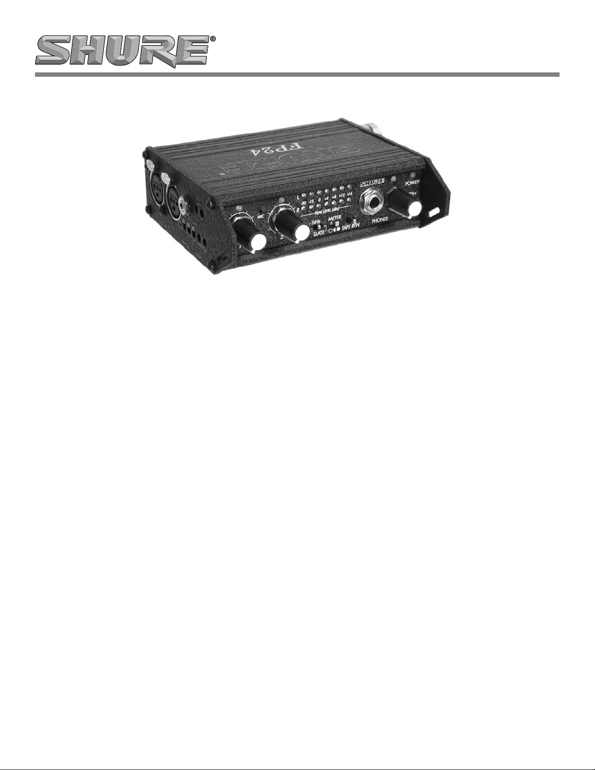
Microphone Mixer
General Description
The Shure FP24 is a studio-quality two-channel, portable, stereo
microphone mixer. With assignable L-C-R inputs, built-in slate microphone, 1 kHz tone oscillator , and headphone monitor, the FP24
is extremely flexible. Its impressive audio performance and comprehensive features make it suitable for the front end of any studio
or field production system. Radio, television, and film production
engineers will especially value its compact size, sunlight-readable
LEDs, and rugged mechanical and electrical construction that
make it able to withstand extremes in the field.
Features
High Performance Microphone Inputs
• Maximum of 66 dB of gain (each input).
• Premium Lundahl input transformers provide superior audio
quality and freedom from interference problems.
• Sealed, conductive plastic potentiometers for long life and
reliable gain adjustment.
• Phantom power, selectable between 48 volts and 15 volts.
• Switchable low-cut filters with 80 and 160 Hz corner
frequencies, 6 dB per octave. Filters are inserted prior to
any active circuitry to maximize headroom.
• Inputs assignable to Left, Center (both left and right) or
Right
Audio Performance
• Dynamic range exceeding 1 10 dB.
• 10 Hz to 50 kHz audio bandwidth.
• Exceptionally low distortion characteristics.
• Discrete, 6-transistor, balanced output drivers provide signal
integrity over long cable runs.
Headphone Monitoring
• Switchable between program audio or external (stereo) tape
returns.
• High current headphone output has level control and peak
indicator.
Level Metering
• Dual-color LEDs indicate clipping and limiter activity for
each channel.
• Sunlight-readable, seven segment GaN LED output meters.
• 3-position LED brightness switch (intensity selector).
Audio Limiters
• “Unclippable” input peak limiters with adjustable limiter
threshold (each input).
• Dual mono or linked stereo limiter operation.
Flexible Powering
• Internal power from two AA batteries with easy access
battery compartment.
• Chassis-isolated 5 to 14 VDC input for easy external DC
powering.
• Power LED indicates low battery power.
Trouble-Free Design
• High-strength, extruded aluminum chassis with protective
metal end panels withstands punishing field conditions.
• All-metal connectors mount directly to the chassis for
durability and RF immunity .
• Free from “Pin 1” grounding problems.
• RF filtering on all inputs and outputs.
2005, Shure Incorporated
27A8727 (Rev. 1)
Printed in U.S.A.
Page 2

Specifications
Gain:
Mic Input to Output, per channel, continuously variable
Output Gain Range
LINE –∞ – 66 dB
TAPE –∞ – 56 dB
Frequency Response:
20 Hz – 30 kHz, +0.2, –0.5 dB; –1 dB at 5 Hz, 50 kHz
(relative to 1 kHz level with 150 ohm source, gain controls set
at 50%)
Equivalent Input Noise:
–126 dBu (–128 dBV) minimum
(150 ohm source, flat weighting, 22 Hz – 22 kHz bandwidth,
gain control set at 50% or higher, phantom power off)
Input Clipping Level:
–10 dBu minimum
Output Clipping Level:
Line: +22 dBu minimum with 100k ohm load
+20 dBu minimum with 600 ohm load
Tape: +11 dBu (2.75 V RMS) minimum with 100k ohm load
Dynamic Range:
110 dB minimum
THD + Noise:
0.05% maximum
(from 50 Hz t o 2 2 kHz @ +4 dBu output level, 22 Hz – 22 kHz
filter bandwidth, gain control at 50%, phantom off)
Common Mode Rejection Ratio:
100 dB minimum at 80 Hz
60 dB minimum at 10 kHz
Channel Separation:
Greater than 80 dB at 1 kHz (gain controls set to 50%)
Inputs:
Transformer-balanced, 2k ohm input impedance
Outputs:
XLR: Active, impedance-balanced, 120 ohm output impedance
Tape (3.5 mm (
ground, 2.4k ohm output impedance
High Pass Filters:
80 Hz or 160 Hz (switch selectable), 6 dB per octave
Phantom Power:
15 V through 680 ohm resistors or 48 V through 6.8k resistors
(switch selectable)
1
/8 in.)): Unbalanced, tip–left, ring–right, sleeve–
Limiter:
Thresholds independently adjustable from
+6 dBu to +18 dBu
10:1 limiting ratio
5 ms attack time, 100 ms release time
Amber/Red LED indicates limiting/clipping
Dual mono or stereo linked
Internal Voltage Rails:
+15 V and –15 V, regulated
Metering:
7 segment GaN (Gallium Nitride) meter with 3 intensities
Peak responding
Power:
Internal: 2 AA batteries
External: 5 – 14 VDC via threaded coaxial connector* (5.5 mm
outer diameter , 2.1 mm inner diameter); Pin positive, sleeve negative; V oltages above 14 VDC cause no damage to unit, but will
open an internal poly fuse that will reset when voltage is removed.
*Threaded coaxial connector provided for use with power supplies not equipped. For instructions on how to solder this connector to a Shure PS20, see Figure 5.
Power LED:
Dual-color LED indicates following:
Green—external DC power or good battery.
Red—less than 1 hour of battery life remaining (with phantom
power off).
Polarity:
All inputs to all outputs, non-inverting.
Pin 2 of XLRs “hot” (to unbalanced inputs and outputs).
Operating Temperature Range:
0 to 70 degrees C (32 to 160 degrees F)
Dimensions:
43 mm x 94 mm x 140 mm (H x W x D) (1.7” x 3.7” x 5.5”)
Weight (FP24 only):
0.8 kg (1.8 lbs.)
Weight (packaged):
1.2 kg (2.6 lbs.)
EMC Certifications:
Meets FCC Part 15 Class B Emissions; Eligible to bear CE mark
(see conformance statement)
Optional Accesories
Balanced line-level-to-microphone-level
in-line adapter A15LA. . . . . . . . . . . . . . . . . . . . . . . . . . . . . . . . . .
FP33/FP24 Interconnection Kit A33LK. . . . . . . . . . . . . . . . . . . .
Inline Polarity Inverter A15PRS. . . . . . . . . . . . . . . . . . . . . . . . . . .
2
Page 3

Front Panel Controls, Connectors, and Indicators
12
6
910 11
4
MIC
1 2
L C R L C R TAPE RTNSLATE
L
–30 –15
R
3
0 +4 +8 +12
1kHz
5
METER
78
Figure 1. Front Panel
1. Input Gain Controls
Sealed, conductive plastic rotary potentiometers.
2. Input Peak/Limiter LEDs
Dual-color LED illuminates red at 3 dB below clipping; illuminates amber to indicate limiter activity .
3. L-C-R Switches (Input Assignment)
Three-position switch assigns inputs to Left, Center (both
left and right) or Right outputs.
4. Slate Microphone
Condenser microphone with AGC activated by momentary
Slate Microphone Switches. Slate Microphone output appears at all outputs.
5. Tone Oscillator/Slate Microphone Switch
Toggle switch activates 1 kHz tone oscillator when switched
to the left position and activates the slate microphone when
momentarily moved to the right position. Microphone inputs
are muted when Tone Oscillator or Slate Microphone are
activated.
6. Output Meters
Indicates peak output level in dBu.
7. Meter Brightness Control
Three-position switch adjusts the intensity of illumination of
the output meter; low illumination, normal illumination, or
super-bright illumination.
+16
13
POWER
FP24
12
INT EXTPHONES
8. Tape Return Switch
Toggle switch allows external audio to be monitored in the
headphones. The center position is FP24 program audio.
The left and right positions monitor tape return audio; the left
position is locking, and the right position is momentary .
9. Headphone Connector
For stereo and mono headphones with ¼” connectors.
10. Headphone Volume Control
11. Headphone Peak LED
Illuminates 3 dB before clipping of either channel of the
headphone circuit and either channel of Tape Return audio.
12. Power Switch
Three-position switch selects the power source. The unit is
powered from internal batteries when in the left position;
powered from external DC source when in the right position.
Center position is off.
13. Power LED
Two-color LED illuminates green when the unit is powered
and changes to red when batteries require changing. For
external DC, the power LED is always green.
Input Panel Connectors and Controls
4
TAPE OUT
48V
12
MIC INPUTS
15V
PHANTOM
123
80
LINK
ON THRESHOLD
160
TAPE RTN
LEVEL
LR
LR
LIMITER
6
Figure 2. Side Input Panel
1.
Mic Inputs
Transformer-balanced XLR inputs accept microphone level
signals. Pin 2 = hot, Pin 3 = cold, Pin 1 = ground.
NOTE: You can use Shure A15LA line adapters to connect balanced, line-level sources to these inputs.
2. Phantom Power
Three-position switch selects either 48-Volt or 15-Volt phantom power for both inputs. Center position turns phantom
power off.
5
7
3. High Pass Filter Switch
Three-position switch selects 80 Hz or 160 Hz corner frequency filters, 6 dB per octave. Filters affect both inputs.
Center position of switch removes filters from the signal
path.
4. Tape Output
3.5 mm (
1
/8 in.) TRS stereo output (unbalanced) can be
used to feed consumer level DAT, MiniDisc, and CD recorders. Tip = Left, Ring = Right, Sleeve = Ground.
5. Tape Return Level Control
Recessed potentiometers adjust Tape Return level feeding
the Headphone Monitor.
6. Limiter Switch
Activates input peak limiter. ON position functions as a dual
mono limiter, with each input signal controlling its own limiter. LINK functions as a stereo limiter, with both left and right
inputs controlled simultaneously. Center position of switch
turns limiters off.
7. Limiter Threshold Level Control
Recessed potentiometers adjust peak level of limiter activation. Can be independently controlled for each input.
3
Page 4

Output Panel Connectors
1(L)
LINE OUTPUTS
3
4
2(R)
5–14 VDC
–
+
5
2
1
TAPE RTN
Figure 3. Side Output Panel
Operational Notes
Input Transformers
The FP24 uses premium Lundahl input transformers with premium magnetic core material to achieve high signal-handling capability, flat frequency response and minimum distortion. Because
these transformers provide galvanic isolation from the driving
source, they offer superior isolation from the adverse and uncontrolled environments of field-production. Their high common-mode
impedance also provides exceptional common-mode rejection.
Output Circuitry and Tape Output
Each line level XLR output of the FP24 uses a discrete, six-transistor, “impedance balanced” output stage. The circuit uses oversized, high speed transistors to achieve low distortion, robust line
driving capability. Pin 2 is driven with signal, and pin 3 is not. (A
common misunderstanding is that a “balanced” output refers to
equal and opposite signals on pins 2 and 3. Correctly, “ impedance
balanced” refers to equal
not equal signal voltages.) T o drive unbalanced inputs, pin 3 can be
grounded or left unconnected. There is no change in signal level
driving balanced or unbalanced inputs.
The FP24’s tape output feeds consumer-level devices, such as
computer sound cards, DAT or MiniDisc recorders, and cassette
recorders. A cable wired with 3.5 mm (
in.) TRS or 3.5 mm (1/8 in.) TRS to Left/Right phono (RCA) connectors will connect the FP24 to such devices.
impedances
Using the FP24 as a Mixer
The FP24 can be used as a simple two-channel mixer. Possible
applications include:
• Quickly reversing the stereo image of a recording without
reconnecting inputs or outputs.
• During set up, checking for mono compatibility by assigning
both inputs to the same output.
• Recording dialog in mono.
• Performing “mix minus” by routing Input 1 to Center and
Input 2 to Right. A summed mono signal of both inputs
appears at the Right output while only Input 1 appears at
the Left output. This is useful for post production processing
of Input 1 audio.
from pins 2 and 3 to ground,
1
/8 in.) TRS to 3.5 mm (1/
Strap Slot
1.
Attachment point for camera straps.
2. Tape Return Input Connector
3.5 mm (
phone monitoring of external audio sources.
Tip = left, ring = right, sleeve = ground.
1
/8 in.) TRS stereo (unbalanced) input for head-
3. Left and Right Line Level Outputs
Active-balanced XLR line-level outputs. +22 dBu peak output level. Pin 2 = hot, pin 3 = cold, pin 1 = ground. Pin 3
can be grounded or ungrounded to drive unbalanced inputs.
4. Battery Compartment
Houses two AA batteries. Insert positive (+) end of batteries
first.
5. External DC Power Input
Accepts 5–14 VDC from an AC to DC transformer or a battery supply. Locking, threaded coaxial connector.
Center pin = positive, sleeve = negative. Use the supplied
threaded connector for power supplies with plug-type connectors (such as the Shure PS20). See Figure 5 for wiring
diagram.
Phantom Power
Use one of the two phantom power settings on the FP24 for microphones that require it. Some microphones need the 48-Volt setting to avoid a loss of headroom and increased distortion. The
15-Volt setting, however, lengthens battery life, and electret-condenser microphones rated for operation at 15 V or less generally
receive no performance benefit from the 48-Volt setting. Consult
your microphone documentation for phantom power requirements.
Dynamic microphones do not require phantom power. A properly
connected balanced, dynamic microphone is not affected by the
presence of phantom power and does not draw any current. However, poorly or incorrectly wired microphone cable can cause audible artifacts in the microphone signal (phantom power can be an
excellent cable tester). It is good practice to turn phantom power o ff
when not needed.
High Pass Filter
To remove excess low-frequency energy in the audio signal, use
either of the two high pass (low cut) filter settings on the FP24. Use
the 80 Hz position for most applications, such as recording speech,
music, and ambient sound. The 160 Hz position is useful for enhancing speech clarity and reducing wind-noise. The high pass filter is a single pole design, 6 dB per octave.
8
When possible, equalize at the sound source by microphone
selection, placement, use of a windscreen, and onboard microphone filtering. Using both the high pass filter on the FP24 and the
one on a microphone has an additive effect, increasing the overall
slope of the roll-off.
Headphone Monitoring and Tape Return
The three position Tape Return switch on the front panel selects
the audio source being monitored:
Center Position—Program audio (normal operation). Monitors
the Left and Right outputs of the FP24.
Left and Right Positions—Secondary audio source. Monitors
audio from the Tape Return input of the FP24. Can be used to verify
that signal is reaching cameras and tape machines. Left is locking;
right is momentary.
Important: The FP24 can drive headphones to very high levels.
Exercise care when monitoring. Reduce the level when the Headphone Peak LED illuminates.
4
Page 5

Limiters
The FP24 has two built-in peak-responding limiters, one for each
input channel. Each limiter has a two-stage circuit: the first stage
keeps the input gain stage from clipping; the second stage limits the
variable gain stage according to the Limiter Threshold control setting. This unique, two-stage topology limits the gain stage directly
after the mic input transformer without changing the input impedance as other “at the mic” limiters do. The circuit enables the FP24
to limit in excess of 50 dB, making it very difficult to clip the unit regardless of the gain setting.
The FP24’s limiters can operate in either either dual-mono or stereo. Use the three-position switch on the input panel to set the limiting mode:
• In the middle position, the limiters are turned off.
• In dual mono operation (ON switch position), the limiters
work independently , responding only to their input signals.
• In stereo-linked operation (LINK switch position), the
limiters control both channels identically . This maintains a
stable stereo image.
When the limiters activate, the Peak/Limiter LED on the front
panel illuminates amber in proportion to the amount of limiting for
each channel.
Tone Oscillator and Slate Microphone
The switch labeled 1 kHz/SLATE on the front panel controls two
functions. The 1 kHz position (left) mutes all inputs and sends a 1
kHz sine wave calibration tone at +4 dBu to all outputs. The tone
oscillator can be used to verify connections and set nominal levels
on recording and transmission equipment.
The SLATE position (right) is a momentary switch position that
activates the built-in slate microphone located behind the front panel. When the switch is held to the right, all inputs are muted and
slate mic signal is sent to all outputs. The slate mic circuit contains
an AGC (automatic gain control) to keep the slate level relatively
constant regardless of the acoustic level. Use the slate microphone
to document takes right at the mixer location when microphones
are on talent or away from the production mixer.
Metering and Clip-Indicators
Three two-color clip-indicators monitor signal levels throughout
the FP24:
1. Above each input gain control, a two-color LED glows red 3
dB below clipping. This clip circuit monitors both the front end
gain stage and the variable gain stage.
2. A headphone-clip LED, located above the headphone level
control, indicates when either channel of the headphone circuit approaches clipping.
3. The headphone-clip LED also indicates when either channel
of the tape return audio is near clipping.
When the limiter is activated, these input LEDs glow amber in
proportion to the amount of limiting.
The FP24 has a seven segment LED output meter that shows
peak output level in dBu. From left to right, the first three LEDs are
separated by 1 5 d B and the remaining LEDs are separated by 4 dB.
This calibration provides a 46 dB-dynamic range with good resolution in the critical signal level range.
The meter uses premium Gallium Nitride (GaN) LEDs which are
visible even in direct sunlight. A three-position switch on the front
panel controls the brightness of the output meter. Choose low, normal, or super-bright.
CAUTION – When set to super-bright intensity, the LEDs in the
output meter can irritate or damage eyes with prolonged direct exposure.
Power Sources and Battery-Life
The FP24 operates from either two internal AA alkaline cells or
an external 5–14 VDC battery supply or AC to DC transformer
(such as the Shure PS20). The power connector is a locking,
threaded coaxial connector. Center pin = positive, sleeve = negative. Use the supplied threaded power connector if necessary (see
Figure 5).
The external DC input supply is galvanically isolated (floating)
from the chassis and the rest of the circuitry. The isolation provides
trouble-free interconnection to other pieces of equipment sharing
the same DC power source. The center pin of the locking DC connector is positive, and the sleeve is negative. Since the external DC
supply is floating, the positive or the negative can be connected to
the chassis with no adverse effects.
Two AA, 1.5 Volt lithium cells can power the FP24 for up to
approximately 11 hours. However, several factors affect how long
a given pair of batteries will last. These factors include battery
chemistry, ambient temperature, use of phantom power, output
meter brightness, and the output drive level of the FP24. The chart
below provides estimates of battery life in different kinds of circumstances. Experimentation can determine expected battery life for
specific setups and environments.
NOTE: AA carbon cells and AA nickel-cadmium cells are not recommended for use in the FP24 since they have lower power capacity than other types and will result in very short service life.
Battery
Type
Eveready AA
No. L91 (lithium)
Duracell AA MN
1500 (alkaline)
Test conditions: 70 degrees F, 42 dB of gain with an acoustic music
source, 600 ohm load, +4 dBu output
Microphone Type and
FP24 Settings
2 dynamic handheld microphones, low
meter brightness, no headphones
2 dynamic handheld microphones, low
meter, low headphone level
2 condenser, 15-Volt phantom powered microphones, normal meter intensity, normal headphone level
2 studio condenser, 48-Volt phantom
powered microphones, super bright
meter intensity, high headphone level
Battery
Life
11 hrs.
6 hrs.
4 hrs.
2 hrs.
Interconnecting the FP24 and FP33
You can connect the balanced, line level XLR outputs of the
FP24 to the mix bus of the FP33 using the Shure A33LK accessory
kit (or construct a cable assembly as shown in Figure 4 on the following page).
Combining an FP24 and a Shure FP33 (or FP32A) mixer yields
a flexible, cost-effective, 5 X 2 field mixing setup with the following
features:
• Simultaneously accepts a stereo microphone, hard-wired
shotgun, and two RF lavalier microphones.
• 48-volt phantom power for all five microphone inputs
• Limiters on the FP24 inputs
• Input assignment switches on the FP24 and pan pots on the
FP33 inputs
• Two output buses—assignable to mic or line level output.
• Master volume and headphone monitoring for all five inputs
controlled from the FP33.
• Compact—FP24 adds little bulk to an existing FP33
package.
• The FP24’s isolated external DC input jack eliminates
ground related interference problems.
5
Page 6

NOTE: When interconnecting the FP24 and FP33, inputs from
the FP24 appear at the FP33 mixbus with their polarity reversed.
(This is unavoidable due to the nature of the interconnection.) To
avoid cancellation or interference effects (e.g., comb filtering) between the signals from the FP24 and FP33 inputs, use Shure
A15PRS polarity inverters on the FP24 inputs, or do one of the following:
• Keep microphones connected to the FP24 as far away as
possible from those connected to the FP33.
• For microphones that must be close together (such as those
in a stereo pair), connect them to the same mixer.
NOTE: If constructing your own FP24/FP33 interconnect cable:
• Keep cable length to a minimum, since the interconnection
is unbalanced.
• Be sure to drive the FP33 mix bus off of pin 2 of the FP24
since the FP24 inputs are reverse polarity with respect to
FP33 inputs.
FP24 XLR–L
820 ohm
FP33 mixbus
FP24 XLR–R
820 ohm
Figure 4. FP24/FP33 Mix Bus Interconnect Cable
Positive: Solder to center pin
(marked with a white stripe on PS20 cable)
Negative: Solder to sleeve
Figure 5. Attaching the Supplied Threaded Power
Connector.
Certification
Authorized under the DECLARATION OF CONFORMITY provision of FCC part 15
as a Class B digital device. Tested to comply with FCC standards. FOR HOME OR
OFFICE USE. This product complies with part 15 of the FCC rules. Operation is
subject to the following two conditions: (1) this device may not cause harmful
interference, and (2) this device must accept any interference received, including
interference that may cause undesired operation. Changes or modifications not
expressly approved by Shure Incorporated could void your authority to operate this
equipment.
This equipment has been tested and found to comply with the limits for a class B
digital device, pursuant to Part 15 of the FCC rules. These limits are designed to
provide reasonable protection against harmful interference in a residential installation.
This equipment generates, uses and can radiate radio frequency energy and, if not
installed and used in accordance with the instructions, may cause harmful interference
to radio communications. However, there is no guarantee that interference will not
occur in a particular installation. If this equipment does cause harmful interference to
radio or television reception, which can be determined by turning the equipment off and
on, the user is encouraged to try to correct the interference by one or more of the
following measures:
Reorient or relocate the receiving antenna
Increase the separation between the equipment and the receiver
Connect the equipment into an outlet on a circuit different from that to
which the receiver is connected
Consult the dealer or an experienced radio/TV technician for help
This class B digital apparatus complies with Canadian ICES–003.
Eligible to bear CE marking.
Conforms to European EMC directive 89/336/EEC: Professional Audio Products
Standard EN 55103 (1996); Part 1 (emissions) and Part 2 (immunity). The FP24 is
intended for use in environments E1 (residential) and E2 (light industrial) as defined in
European EMC standard EN 55103. It meets the applicable tests and performance
criteria found in the standard for these environments. EMC conformance is based on
the use of shielded interconnecting cables.
N 108
Limited Two-year Warranty
Shure Incorporated (“Shure”) hereby warrants that this product will be free from defects in materials and workmanship for a period of two years from date of purchase.
At its option Shure will repair or replace the defective product and promptly return it to
you, or refund the purchase price. You should retain proof of purchase to validate the
purchase date and return it with any warranty claim.
If you believe this product is defective within the warranty period, carefully repack
the unit, insure it, and return it postage prepaid to:
Shure Incorporated
Attention: Service Department
5800 W. Touhy Avenue
Outside the United States, return the product to your dealer or Authorized Service
Center.
This warranty does not apply in cases of abuse or misuse of the product, use contrary to Shure’s instruction, or unauthorized repair. Al l im p lied WARRANTIES OF MERCHANTABILITY o r FITNESS FOR A PARTICULAR PURPOSE are hereby disclaimed
and Shure hereby disclaims liability for incidental, special, or consequential damages
resulting from the use or unavailability of this product.
Some states do not allow limitations on how long an implied warranty lasts, or the
exclusion or limitation of incidental or consequential damages, so the above limitation
may not apply to you. This warranty gives you specific legal rights, and you may have
other rights which vary from state to state.
Evanston, Illinois 60714–4608 U.S.A.
FCC Declaration of Conformity
We of
Shure Incorporated
5800 W. Touhy Avenue
Evanston IL 60714–4608 U.S.A.
847–600–2000
declare under our sole responsibility that the following product,
Model: FP24 Name: FP24 Microphone mixer/preamplifier
was tested and found to comply with Part 15 of the FCC rules.
Operation is subject to the following two conditions: (1) this device may not cause
harmful interference, and (2) this device must accept any interference received, including interference that may cause undesired operation.
Testing was completed by the following NVLAP or A2LA accredited laboratory:
L.S. Compliance, Inc.
W66 N220 Commerce Court
Cedarburg, Wisconsin 53012
Telephone 262–375–4400
Fax 262–375–4248
Shure Incorporated, Manufacturer.
Signed:
Name, Title: Craig Kozokar , Project Engineer, EMC
SHURE Incorporated Web Address: http://www.shure.com
5800 W. Touhy Avenue, Niles, IL 60714-4608, U.S.A.
In U.S.A., Phone: 1-847-600-2000 Fax: 1-847-600-1212
In Europe, Phone: 49-7131-72140 Fax: 49-7131-721414
In Asia, Phone: 1-852-2893-4290 Fax: 1-852-2893-4055
6
International Fax: 1-847-600-6446
Date: Sept. 15, 2000
 Loading...