

Page 1
GENERAL
The
FP22 is a
provides
unique
headphone feeds from
capability of monitoring mono, stereo and mixed mono and
battery-powered stereo headphone amplifier that
any audio input source. It has the
stereo inputs. The FP22 monitors and combines these signals in
the headphones without affecting the original signal. Stereo or
headphone outputs appear on 1/4-inch phone or mini 3.5 mm
mono
stereo
jacks. The FP22 can drive headphones to very loud levels.
It
is ideal for anyone in the broadcasting, sound reinforcement or
audio recording fields who needs a flexible, high–quality headphone
monitor
.
The FP22 is excellent for:
• Line
checking applications
•
Providing multiple headphone feeds
•
On stage in-ear monitoring
•
Boosting headphone circuits
•
Headphone foldback in recording studios
• Practicing musical instruments or mixed vocals through headphones
monitoring a stereo source
while
Features:
Exceptionally wide frequency response and dynamic range
•
•
High-impedance bridging inputs do not load signal sources
•
Capable of mixing mono and stereo inputs in headphone outputs
•
Complete user control of headphone volume
• Loopthrough
become
• 30
dB pad for stereo line input to accommodate a wide range of line level
sources
• Balanced
level
•
Separate XLR volume control on pull-out control knob
1/4-inch stereo phone jacks (can be internally switched
separate left and right inputs)
loopthrough XLR connectors switchable from mic to line
to
Shure
Brothers Incorporated
222 Hartrey A
venue
Evanston IL 60202-3696 U.S.A.
Model FP22 User Guide
•
Overall headphone balance control
•
Overall stereo/mono switch for headphones
•
LED power indicator
•
Powered by easily obtainable 9–volt
24 Vdc power supply (such as Shure Model PS20 or PS20E)
to
1
•
/4-inch and 3.5 mm stereo headphone jacks
• Effectively shielded for low susceptibility to radio-frequency interfer-
(RFI)
ence
SPECIFICATIONS
Frequency
20 Hz to 20 kHz, +1, –3 dB (stereo line input)
50 Hz to 18 kHz, +1,–3 dB (mono XLR input)
Equivalent Input Noise
–125 dBV (maximum gain; source resistance 150 Ω; 20 Hz to
20 kHz)
oltage Gain
V
(pa
T
otal Harmonic Distortion
Less
stereo
Input Clipping Levels
Mic level
Line
Output
Headphones
Impedance
Input Impedance
XLR (mic level)
XLR
Stereo
Stereo
Headphone
10.2 Ω ± 10%
Response
(ref 1 kHz)
(at 1 kHz)
Source
Input
XLR
Impedance
150
(mic level)
XLR
600
(line level)
Stereo line
600
(pad at 0 dB)
Stereo line
d at –30 d
B)
600
than 0.5% measured at –8 dBV into 8 Ω
line input; 50 to 18 kHz mono XLR input)
(at 1 kHz)
.
. . . . . . . . . . . . . . . . . . . . . . . . . . .
level
.
. . . . . . . . . . . . . . . . . . . . . . . . . . . . .
Level at Clipping
FP22 Out-
put
63
Ω
1.2 V (1.6
dBV)
8
Ω
500 mV (–6
dBV)
. . . . . . . . . . . . . . . . . . . . . . . . . . .
(line level)
Line (pad at 0)
. . . . . . . . . . . . . . . . . . . . . . . . . . . .
. . . . . . . . . . . . . . . . . . . . . .
Line (pad at 30 dB)
Output Impedance
alkaline
battery or by external 12
Gain
o 63
80
29
26
–4
± 5
± 5
± 4
± 4
Ω)
dB
dB
dB
dB
(int
Ω
Ω
Ω
Ω
(20
160 mV (–16 dBV)
50 V (+34 dBV)
Headphones
Sensitivity
106 dB at 1
Head-
phones SPL
120 dB
mW
95 dB at 1
1
mW
. . . . . . . . . . . . . . . . . .
(at 1 kHz)
Gain
(into 8
74
± 5
23
± 5
21
± 4
–10
Hz to 20
10 dB
6.3 kΩ
66 kΩ
50 kΩ
53 kΩ
± 4
Ω)
dB
dB
dB
dB
kHz
±10%.
±10%.
±10%.
±10%.
1997, Shure Brothers Inc.
27A8362
(QE)
Printed in U.S.A.
Page 2

Phase
Input in phase with output. Pin 2 of XLR input in phase with
and ring of all Headphones jacks.
tip
Power
.
Internal
Battery
. . . . . . . . . . . . . . . . . . . . . .
Life
.
. . . . . . . .
External
Current
T
emperature Range
Operating 0o to 49oC (32
Storage –29o to 70oC (–20o to 165oF).
.
. . . . . . . . . . . . . . . . . . . . . . . . . . . . . . .
drain (typical)
.
. . . . . . . . . . . . . .
. . . . . . . . . . . . . . . . . .
. . . . . . . . . . . . . . . . .
One 9 V alkaline battery
Approximately 15 hours under
normal operating conditions
12 to 24 Vdc
1
1 mAdc; 80 mAdc
(clipping)
at 9 Vdc
o
to
120oF).
Connectors
Loopthrough
Two
3-pin balanced XLR-type connectors (one male, one fe
male)
1
/4-inch stereo phone jack (tip-left; ring-right; sleeve-
Two
ground)
Headphones
T
wo 1/4-inch stereo phone jack headphone outputs
T
wo 3.5 mm stereo mini jacks
Power
6.5 mm coaxial power connector (tip +, sleeve –)
Case
Die-cast zinc; matte black enamel finish
Overall Dimensions
80.9 mm H x 55.5 mm W x 153 mm D
(3-3/16 x 2-3/
x
6-1/16 in.)
16
Net Weight
450 grams (1 lb)
NOTE
: The FP22 is lightweight and can be clipped to a belt or
trousertop,
clip
or to D-rings on other equipment. The FP22 belt
is attached to
the case with two easily removable screws.
The FP22 will stand on a flat surface, and several units can
be stacked together with their belt clips removed.
SETUP
Battery Replacement
1.Use
a coin or screwdriver to
er
in either direction to open the battery compartment door
turn the 1/4-turn lockscrew fasten
.
2.Insert a fresh 9–volt alkaline battery (NEDA 1604A, Duracell
MN1604A,
The
tery
minals
Eveready 522, or equivalent)
in the compartment.
battery compartment is designed so that the polarized bat
terminals cannot be inserted incorrectly
. Plated spring
ter
ensure solid electrical contacts.
External Power
coaxial dc power jack accepts a dc voltage from
The
volts. External dc power feeds a regulator to power the FP22
cuitry.
The dc input jack is directly compatible with Shure Model
12 to 24
cir
PS20 or PS20E Power Supplies. The tip of the coaxial jack is
positive
serted
(+), the sleeve is negative (–). A coaxial power plug in
into the external power jack disables the internal battery
power.
Signal Connections
Mono XLR
—Microphone– or line–level signals
1.Set the Mono XLR Mic-Line switch to the appropriate signal
level.
2.Connect a balanced microphone or line level signal to either
Mono XLR jack.
3.If
loopthrough
is desired, use the unused XLR connector as an
output.
NOTE:
N
o d
amag
e will r
esul
t i
f the M
ic-Lin
e s
witc
However,
are
m
onitore
Stereo Line
1.Connect
o
bjectionabl
d with t
e d
istortio
he switc
h i
n the M
n may r
—Line– or Aux–level signals only
a 1/4-inch stereo connector to either Stereo Line jack.
h i
esul
t i
f line l
ic position.
2.If loopthrough is desired, use the unused 1/4-in. stereo connector
as an output.
3.Set th
e f
ron
t p
ane
l S
tere
o Line Pad to the 0 dBm l
position. The –30 dB position is used when the FP22 line–level
input signals ar
NOTE:
As explained in the
FP22
can
e +
4 dBm o
r g
reater.
Internal Switches
description, the
accept left and right input signals on separate con
nectors. Stereo Line jack (1) is left, Stereo Line jack (2) is
right.
Headphones
-
1.Connect
NOTE:
headphones to the Headphones A and B jacks.
Each pair of Headphones jacks consists of one 1/4-inch
and one 3.5 mm stereo connector. Only one connector of
each
pair can be used at
connector
disconnects its associated 3.5 mm connector
one time. Plugging into the 1/4-inch
OPERATION
NOTE:
A simplified block diagram on the side of the FP22 pro-
vides a quick reference to its functional circuitry
1. Rotate the overall Volume control clockwise to power the
The Power LED indicator lights to
FP22.
show that the unit is
on. Turn the level control carefully to avoid excessive headphone
levels. The V
signal
and Stereo Line signal.
olume control adjusts both the Mono
WARNING
The FP22 can produce ear–damaging headphone
levels. Turn the headphones Volume control up
slowly
when making adjustments.
2.Pull out the Volume control knob and rotate clockwise to increase
the volume level of the Mono XLR signal
justment
tion
3.Rotate
right
4.If
-
Mono.
INTERNAL SWITCHES
signal
tically mounted printed circuit board inside the unit adjacent to
the Loopthrough phone jacks. To access the switches, remove
the
will not af
fect the overall volume. A center detent posi
provides a starting volume level for the Mono XLR signal.
the Balance control left or right to control the overall left/
signal balance.
mono monitoring is desirable, set the
Two
switches
path
are located inside the FP22. These control the
through the unit. The switches are located on the ver
Stereo/Mono switch to
three Phillips-head screws on the side panel of the unit.
Internal Switch S-104 consists of two independent single-
pole,
single–throw switches
input
-
-
signal:
1.When
S104-1 and -2 are in the On position, the Mono XLR sig
nal
is routed to both left and right earphones.
2.When S104-1 is in the On position and S104-2 is in the Off
position,
the Mono XLR signal goes to the left channel.
controlling the path of the Mono XLR
3.When S104-1 is in the Off position and S104-2 is in the On
position,
4.
If both S104-1 and -2 are in the Off position, NO signal from
the Mono XLR signal goes only to the right
the Mono XLR input appears at the headphone outputs.
Internal Switch S105 is a two–position slide switch that
changes
puts
1. When interna
the Stereo Line jacks from Loopthrough TRS stereo in
to separate left and right mono inputs.
l s
witc
h S105 i
accept
a s
tere
left; ring-right
o s
igna
; s
l o
leeve-ground)
n a s
s set for s
ingl
e 1/4-inc
. This a
tereo
llow
, the S
h s
tere
s for a l
o c
s set i
ncorrectly.
eve
ine–leve
.
only
. This ad
channel.
tere
o Line j
onnecto
oopthroug
l s
l s
ignals
ignal
.
XLR
acks
r (
tip-
h o
f a
-
-
-
-
-
-
2
Page 3

stereo signa
in
p
arallel.
2.When
individual
stereo
jack
(2)
with
S105 set for Mono.
TYPICA
l s
inc
e both 1/4-inc
h S
tere
o Line j
ack
s are c
onnected
internal switch S105 is set for Mono, the FP22 accepts
left and right 1/4-inch mono connectors
to provide a
signal. Stereo Line jack (1) is the left input; Stereo Line
is the right input. No loopthrough capability is available
L M
ONITORING CONNECTIONS
1.One Mono Input. A mono signal connected to an XLR or
phone jack will be monitored as a mono headphone signal.
(When using the Mono XLR connectors, the Line/Mic switch
should
be set to match the input.)
2.One Stereo Input. A stereo signal connected to the Stereo
Line
jacks can be monitored as a
phones
or as a mono output.
3.One
Stereo
Input Plus One Mono Input.
stereo output on stereo head
A mono signal input
through the Mono XLR connector and a stereo signal input
through
put,
the Stereo Line jacks can be monitored as a mixed out
with both signals appearing in the stereo headphones.
4.Three Mono Inputs - Stereo Headphone Signal Output.
Three mono signals can be accepted through the mono-XLR
jacks
and the stereo line jacks, and mixed and monitored as a
stereo
signal in the stereo headphones.
NOTE:
The FP22 can be modified so that all input jacks are in
parallel.
modification
Shure’s
This duplicates the Shure FP12
allows monitoring in mono only
in functionality
. Please contact
. This
Product Applications Group for details on this modifi
cation.
INTERCOM CAPABILITY
The FP22 can interface to commercially available intercom
systems,
low
can
be
such as R
show how to interface
be monitored.
obtained from the intercom manufacturers.
Telex Intercom Systems
TS, T
elex and ClearCom. The diagrams be
the FP22 to these systems and what
More information about intercom systems can
(Figure 1)
Telex uses a standard balanced audio line. No modification
is
required to interface the FP22 with T
1.
Use the Mono XLR Loopthrough connections.
2. Mon
o X
LR level switch shoul
volts phantom power on the intercom line is passed
3.24
the
FP22.
1
2
3
d b
AUDIO
AUDIO (–)
FIGURE
RTS
and ClearCom Systems
(Figure 2)
elex intercoms.
e se
t to the Line p
(+)
REF
1
osition.
through
+24 VDC
+24 VDC
These two systems use an unbalanced audio line which re-
use of the 1/4-inch line connectors of the FP22 for opera
quires
tion. The Y–cable depicted in Figure 2 is required for RTS and
ClearCom intercom systems.
1.The
above Y–cable
2.Set
internal switch S105 to Stereo (factory setting).
Wiring
is placed in-line into the intercom system.
for R
TS and ClearCom Systems
Pin RTS ClearCom
2 Audio
3
1
channel 1, 24Vdc
Audio channel 2, 24 Vdc
Reference (ground)
Audio, 18-36 Vdc power
Audio, 12 Vdc call signal
Reference
(ground or com
mon)
-
-
1
2
3
TO STEREO LINE
LOOPTHROUGH
CONNECTION ON FP22
SLEEVE
RING
FIGURE
TIP
2
SPECIAL APPLICATIONS
Troubleshooting stage sound systems. The FP22 can be
to trace a signal line when one or more
used
microphones are not
working on stage. To locate the malfunction, loop the signal
through the FP22 wherever an XLR or phone connector is lo-
and monitor the signal.
cated
Field monitoring applications can be set up by inserting
FP22
units “in line” without af
-
On
stage monitoring.
in-ear
monitor system can be created. From a mixing console a
stereo
signal can be looped through
fecting the signals.
With
the FP22, an ef
to multiple FP22’
fective on–stage
Mono XLR jack can be used for an individual’s microphone or
musical
phone
instrument
instrument. Each performer has control of overall head
volume as well as a mix control of their
individual voice or
with the stereo signal.
Boosting headphone output. The FP22 can be used to
boost the headphone output of existing devices. The stereo
headphone output of an audio device can be connected to the
Stereo Line connectors of the FP22. The FP22 will provide a
high–quality
another
headphone output with the ability to loop through
FP22.
Using the FP22 as a two-stage intercom system. A twostage
intercom system can be created by
units
with a single standard microphone cable. Each person con
a Shure SM12A or other headset
nects
and
earphone input
crophone
signals appear at each FP22 headphone output.
connector to their individual FP22. Both mi
connecting two FP22
microphone’
Practice headphone amplifier for microphones or other
sources, such as electric instruments, synthesizers, etc. Connect the output from any instrument into the FP22 and monitor
headphones.
the
2
1
3
s, while the
to
s XLR output
-
-
-
-
3
Page 4

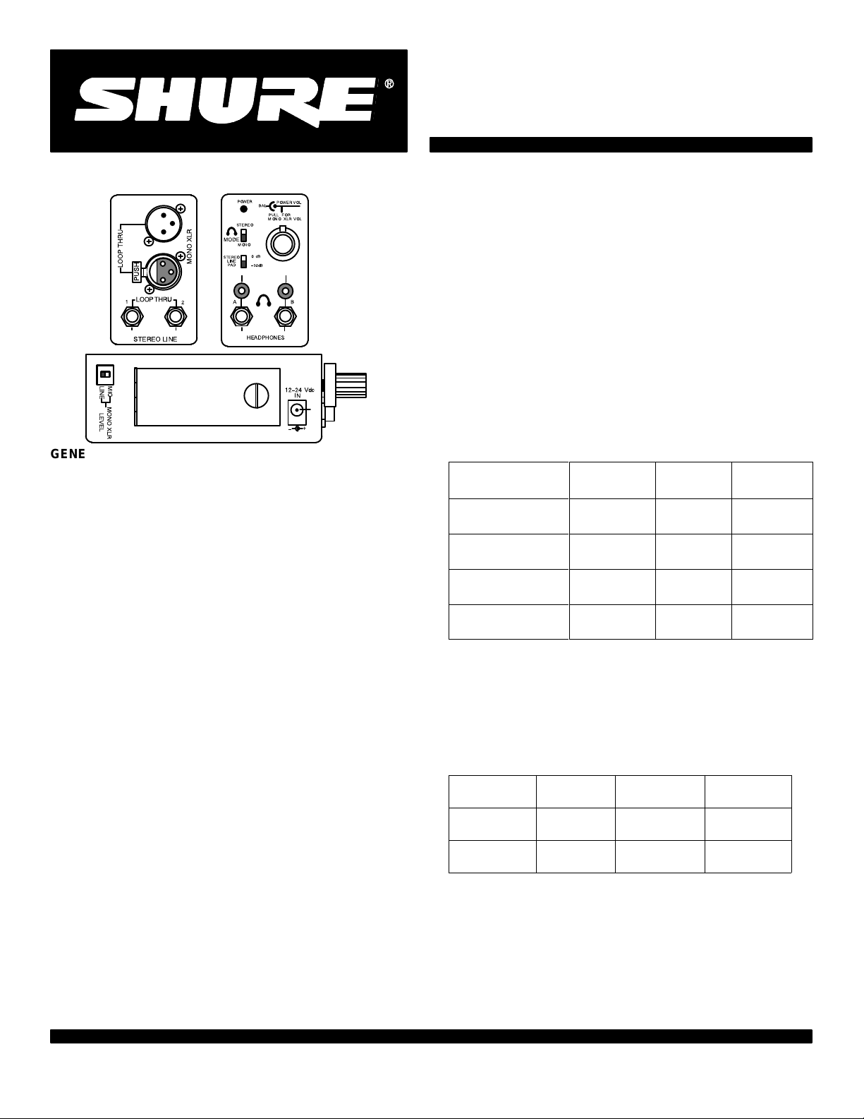
Stereo
Line Jacks
(Unbalanced)
Dual function jacks.
Factory supplied so that tip, ring,
sleeve stereo signal applied to
jack can be
one
looped through to
other jack (tip-left, ring-right,
sleeve-ground). Jacks can be internally switched so that two
mono phone jacks can be input
and monitored in stereo without
loopthrough (see Internal
switches).
THRU
LOOP
PUSH
LOOP THRU
1
MONO XLR
2
Mono XLR Connectors
(Balanced) Loopthrough connec-
accept both mic and line level
tors
signals. Volume adjusts with pull
out triple–function Volume control
detent is nominal
(center
volume).
LED Powe
Lights whe
r I
ndicator
n FP22 i
s turne
d o
n.
Stereo/Mono Headphone Mode
Switch
Changes headphones from stereo
to mono. Especially useful when
monitoring monaural signal con-
t
o stere
o line j
nected
Stere
o Line P
acks.
ad
Reduces gain on Stereo Line sig nals by 30 dB. Especially useful
with signal levels of +4 dBm or
greater.
Mono XLR Mic/Line Switch
Selects between microphone and
line level signals coming into XLR
(50 dB
connector
mic preamp when switch is in
fore
pad inserted be
Line position).
STEREO
LINE
Balance Control
(Outer ring of triple function Volume
MODE
STEREO
LINE
PAD
POWER
STEREO
MONO
0 dB
–30dB
BAL
PULL FOR
MONO XLR VOL
POWER/VOL
control.) Overall headphone balance
r d
n V
etent.
olum
e C
ontrol
control with cente
Tripl
e F
unctio
Incorporates On/Off switch, overall
Volume control (master volume), and
Mono XLR Volume (on the pullout).
Center–detented Mono XLR volume
n
omina
l l
at
evel.
3.5 mm Stereo (3-Circuit) Mini
Headphone
Mono or stereo program monitor
AB
1
/4-Inch Stereo (3-Circuit) Head-
phone
-
HEADPHONES
Mono or stereo program monitor; us
these jacks disables 3.5mm jacks.
ing
Connectors
.
Connectors
-
MIC
LINE
MONO XLR
LEVEL
Battery Compartment
Requires one 9 V alkaline battery
12–24 Vdc
IN
+
–
.
External Power Jack
Accepts external supply voltage
from 12 to 24 Vdc (such as Shure
PS20 or PS20E Power Supplies).
is positive, sleeve is negative.
Tip
4
Page 5

REFERENCE
DESIGNATION
BT1
D101–D107, D1
13, D1
15
D108–D110
D111–D112
D114
J101
J102
J103–J104
J105, J107
J106, J1 08
J109
L101–L104
L105–L109
MP1
MP2
MP3
MP4
101, Q103
Q102, Q104
Q105
Q106
Q107–Q111
R106/R127/R144/R157/R158
S101–S102, S106
S103
S104
S105
T1
U101
U102
U103
*Commercial
alternates are acceptable equivalents; for optimum performance, only direct replacement parts should be used.
REPLACEMENT PARTS LIST
DESCRIPTION
Battery
, Alkaline, 9 V
Dual Diode Assembly
Diode
Diode, Schottky
Light–Emitting Diode, Red
Connector, 3–Socket, MONO XLR
Connector
Phone Jack, Stereo, STEREO LINE LOOPTHRU
Phone Jack, Stereo Switching, HEADPHONES
Phone Jack, Stereo, HEADPHONES
Connector
Ferrite Bead Ring
Filter
Battery Door Assembly (with hinge, lockscrew)
Belt Clip (without screws)
Knob, Inner (small)
Knob, Outer (larger ring)
Transistor, NPN
Transistor, PNP
Transistor, PNP
Transistor, NPN
Field Ef
Potentiometer
20%, VOLUME
Switch, Slide, DPDT, MONO XLR LEVEL, STEREO
LINE PAD, MONO/STEREO
Part of R106/R127/R144/R157/R158
Switch, DIP, DPST
Switch, Slide, DPDT
Transformer
Integrated Circuit, Dual Op Amp
Integrated Circuit, Quad Op Amp
Integrated Circuit, V
, 3–Pin, MONO XLR
, Power
, 12–24 VDC IN
fect T
ransistor
, Ganged, 100k/250k/250k/200k/200k,
, Input
oltage Regulator
SHURE PART NO. AND/OR
COMMERCIAL ALTERNATE*
Duracell MN1604
Shure 22202FT
Shure 22203FT
Shure 22204FT
Shure 22205FT
; NEC 1SS123
; T
oshiba 1SS193
; T
oshiba U1GWJ44
; T
oshiba TLR124
Shure 95A8381; ITT Cannon XLM–3–31PCV
Shure 95A8400; ITT Cannon XLM–3–32PCV
Shure 22201FT
Shure 20202FT
Shure 20203FT
Shure 30252FT
; Hosiden HLJ0546–01–010
; Hosiden HLJ3305–01–3080
; Hosiden HSJ0926–01–1010
; Hosiden HEC0470–01–630
Shure 80A250; TDK BF30–3.4x6x1
Shure 22801FT
; TDK ZBF503S–01
Shure 10209FT
Shure 53A1891
Shure 95A8539
Shure 95B8539
Shure 22603FT
Shure 22604FT
Shure 22605FT
Shure 22606FT
Shure 22606FT
; Sanyo 2SD438FMP
; Sanyo 2SB560FMP
; T
oshiba 2SA1015GR
; T
oshiba 2SC1851GR
; Siliconix SST177
Shure 22206FT
Shure 55A8020; Nikkai AS–22AH
Shure 22401FT
Shure 22402FT
; Fujisoku DSS2–02
; Nikkai SS–22SB1
12
Shure 22501FT
Shure 86A8953; Motorola MC33178P
Shure 22601FT
Shure 22602FT
; Motorola MC33179P
; Motorola MC7809CT
5
 Loading...