

Page 1
Shure FP Wireless
FP Wireless System
Système sans fil FP
FP-Drahtlossystem
Radiosistema FP
Draadloos systeem FP
Sistema inalámbrico FP
Sistema Sem Fio FP
Система FP Wireless
©2012 Shure Incorporated
27B16755 (Rev. 1)
FP5 FP1 FP3 FP2
Printed In U.S.A
Page 2

Page 3

FP Wireless System
Featuring a comprehensive selection of system configurations with key wireless audio technologies and components, FP Wireless provides the ability to capture crystal-clear audio with confidence. With simple and flexible components, including a portable receiver and XLR plug-on transmitter, it has never been
easier for audio to be captured in the demanding and dynamic videography and electronic field production (EFP) environments.
FP1 Bodypack Transmitter
Lightweight, durable housing; for use with TA4Fconnection microphones
including lavaliers and
headsets
FP2 Handheld
Transmitter
Lightweight, durable
housing; available with
either the legendary
Shure SM58® cardioid
dynamic wireless capsule or with
the VP68 condenser omnidirectional capsule; compatible with all
Shure wireless capsules
FP3 Plug-On
Transmitter
Durable metal housing, ergonomically designed for
comfortable grip; XLR connectivity
allows for use with any wired dynamic XLR microphone
Features
• Audio Reference Companding for crystal-clear audio
• Automatic Frequency Selection locates an open frequency at the touch of a button
• Automatic Transmitter Setup instantly syncs the transmitter to the receiver frequency
• Up to 12 compatible systems simultaneously
• All components powered by 2 AA batteries – no power cord required
• Transmitter gain attenuation control manages input level
FP5 Portable Receiver
Lightweight, durable
housing, suitable for
mounting on camera or
person, diversity antennas, output via TA3F
cable to either XLR or
1/8” connectors.
Furnished Accessories
Microphone Clip (FP2) Plug-on Transmitter Belt Clip and
Protective Skin (FP3)
Camera Shoe Mount (FP5) TA3F-to-XLRm Audio Cable
TA3F-to-3.5mm Dual-mono Audio
Cable
1
Page 4
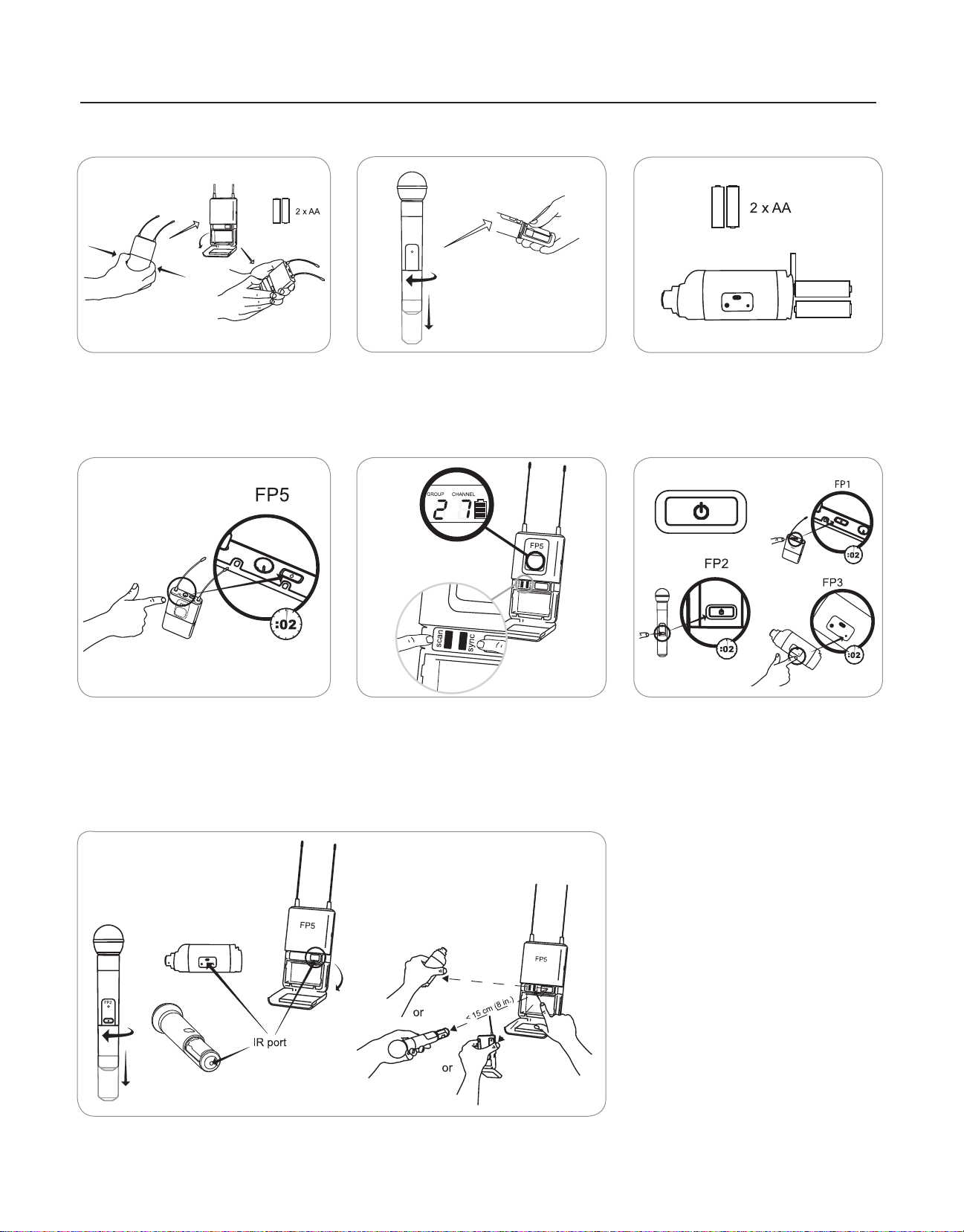
Quickstart
Install Batteries
FP1 - FP5
Power up the FP5 Receiver Group scan for open frequencies Power up the transmitter
FP3FP2
Sync transmitter and receiver
2
Page 5
FP2
FP1
FP1FP2
⑨
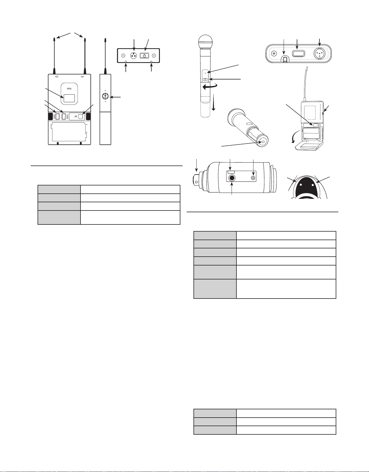
FP5 Receiver
① Power LED
Green
Yellow
Red
Flashing red on
power up
② RF LED
Illuminates when successfully synced to a transmitter (or manually
tuned to a transmitter's frequency)
③ Power Button
Press and hold to power on or off.
④ Infrared (IR) port
Sends infrared beam to synchronize frequencies.
⑤ TA3M Jack
Use with TA3F cable for audio out.
Power on
Low battery alert
Critical low battery, replace immediately
Battery dead
FP3
Transmitter Controls and Connectors
① Indicator LED
Green
Flashing green
Flashing red
Solid red
Flashing red on
startup
Rapid flashing
red after
synchronization
Ready
Controls locked
IR transmission in progress
Battery power low
Batteries dead (transmitter cannot be turned
on until batteries are changed)
Transmitter and receive incompatible; contact
your Shure reseller
⑥ Audio Output Gain
Adjust audio output level to devices such as cameras or recorders.
⑦ LCD Screen
Displays current settings for GROUP and CHANNEL and battery life.
⑧ Scan Button
Group scan: Push and hold (3 sec.) to find an open group and channel.
Channel scan: Push and release to find an open channel in the current
group.
⑨ Sync button
Align receiver and transmitter and press sync. Blue IR LED indicates
successful sync.
Note: Press sync and scan buttons to manually enter group and channel numbers
② Power Button
Press and hold to power on or off.
③ Infrared (IR) Port
Receives infrared beam to synchronize frequencies. When using
multiple systems, only one transmitter IR port should be exposed at a
time.
④ 4-Pin Microphone Input Jack
Use with with a TA4F connector for a lavalier or headset microphone.
⑤ Audio Input Gain
Adjusts audio level.
⑥ XLR Connection (FP3 only)
Plug into an XLR microphone or the output of an audio device.
⑦ Audio Input Level Indicator (FP3 only)
⑩ Antennas
Two antennas for diversity reception.
Red
Yellow
Green
3
Signal clip
Nominal peak
Audio present
Page 6

Adjusting Gain
FP1 and FP3
Perform a sound check. Use the
audio gain control located on the
side (FP1) or front (FP3) of the
unit to adjust the gain up (+) or
down(−)untildesiredlevelis
reached.
FP3 only: Adjust so the audio
input level indicator flickers yellow
at peak sound levels.
FP1
FP3
FP2
The handheld transmitter normally
does not require adjustment and
should be left at 0dB for most applications. Only use the –10dB setting for loud singing or other high
SPL applications if there is noticable
distortion.
Access the gain adjustment switch
by unscrewing the head of the microphone. Use the tip of a pen or a small
screwdriver to move the switch:
0dB: For normal use.
–10dB: Use only if audio distorts due to high SPL levels.
PGXD
FP2
BIAS
AUDIO
-10dB
0dB
AUDIO
-10dB
0dB
Single System Setup
1. Perform a group scan:
Press and hold the scan button for 3 seconds. After the scan completes, the new group and channel is automatically activated and
saved.
2. Synchronize the transmitter:
Align the transmitter and receiver infrared (IR) ports and press the
sync button.
After a successful sync, the transmitter LED momentarily flashes and
the blue RF LED illuminates.
Manual Group and Channel Selection
(receiver only)
Important: Most single-system applications do not require manual group
or channel settings--use an automatic frequency scan instead. However,
it may be useful for some applications, such as to tune to and record audio directly from a microphone in a compatible wireless installation.
To set the group:
1. Press the scan and sync buttons simultaneously. The GROUP display
flashes.
2. Press the sync button to change the group number.
3. Press scan to accept the selected group.
4. Press scan again to save and exit.
5. If desired, perform a channel scan to select an open channel in that
group.
To set the channel:
1. Press the scan and sync buttons simultaneously. The GROUP display
flashes.
2. Press scan to move to the channel setting. The CHANNEL number
flashes.
3. Press the sync button to advance to the desired channel number.
4. Press scan to save and exit.
Note: Remember to sync the transmitter to the receiver.
Multiple System Setup
Use the following steps to ensure the best performance when using multiple wireless systems at the same location.
1. Turn all receivers on and all transmitters off.
Note: Turn on any other digital equipment that could cause interference during the performance so it will be detected during the frequency scans in the following steps.
2. Perform a group scan using the first receiver by pressing and holding
the scan button for 3 seconds.
3. Turn on the first transmitter and sync it to the receiver.
For each additional system:
1. Manually set the group number to match the first receiver (see Manual
Group and Channel Selection).
2. Perform a channel scan by pressing the scan button.
3. Sync the transmitter to the receiver.
Important: After syncing each transmitter, leave it on so that scans from
the other receivers do not select that channel. Be sure only one transmitter IR port is exposed when synchronizing each system.
Automatic Frequency Scan
If you experience RF interference, switch to a new channel using the
channel or group scan.
Channel scan: Press the scan button on the receiver. Switches to new
channel in the same group.
Group scan: Press and hold the scan button for 3 seconds. Finds a new
group and selects an open channel in that group. (Do not use in multiple
system setups unless all systems are moved to the same group.)
Locking and Unlocking the Transmitter
Locking the transmitter prevents accidental changes during
performances.
To lock the controls: With the transmitter off, hold the power button
down until the green LED flashes (~5 seconds)
To unlock the controls: With the transmitter on, hold the power button
down until the green LED flashes (~5 seconds)
4
Page 7

Troubleshooting
Issue Indicator Status Solution
No sound or faint sound Transmitter power light on, receiver
Distortion or unwanted noise
bursts
Distortion increases gradually Transmitter or receiver power LED
Cannot turn transmitter or
receiver on
blue RF LED off
Transmitter power light on, receiver
blue RF LED on
Receiver power LED off, red, or
blinking red
Transmitter power LED red or
flashing red
Transmitter power LED off Turn on transmitter
N/A Remove nearby sources of RF interference (CD players, cell phones,
red
Power LED flashing red Replace batteries
Sync the transmitter to the receiver
Move closer to and maintain line-of-sight with the transmitter. Move away
from metal surfaces and digital equipment.
Verify all sound system connections
Adjust gain settings on the transmitter and receiver. Make sure the
handheld transmitter gain is at the 0dB setting.
Insert fresh batteries or power on the receiver
Replace transmitter batteries
If indicator continues flashing red after batteries are replaced, the
transmitter and receiver may belong to incompatible frequency bands.
Contact your Shure reseller for assistance.
Make sure the +/- indicators on batteries match the transmitter terminals
Insert fresh batteries
computers, digital effects, in-ear monitor systems, etc.)
Change receiver and transmitter to a different frequency
Reduce transmitter gain
Replace transmitter batteries
If using multiple systems, change the frequency of one of the active
systems
Replace batteries
Tips for Improving System Performance
• Maintain a line-of-sight between transmitter and receiver
• Avoid proximity to metal surfaces and digital equipment that could cause RF interference, such as computers, cell phones, LCD screens, and other
audio electronics.
Furnished Accessories
Microphone clip (FP2) WA371
Plug-on Transmitter belt clip and protective skin (FP3) AFP301
Camera Shoe Mount (FP5) AFP511
TA3F-to-XLRm audio cable WA451
TA3F-to-3.5mm dual-mono audio cable WA461
5
Page 8

Specifications
FP5
Working Range
Line of Sight
Tonekey 32.768 kHz
Audio Frequency Response 45 to 15000 Hz (±2 dB)
Total Harmonic Distortion
Ref. ±38 kHz deviation with 1 kHz tone
Dynamic Range >100 dB, A-weighted
Operating Temperature Range -18°C (0°F) to +57°C (135°F)
100 m (300 ft)
Note: Actual range depends on RF signal absorption, reflection and interference.
Note: Dependent on microphone type
<0.5%, typical
Note: Battery characteristics may limit this
range.
FP1
Gain Adjustment Range −10 to +20 dBV
Input Impedance 1MΩ
RF Output Power 10 to 30 mW
varies by region
Pin Assignments
TA4M
Dimensions 108 mm x 64 mm x 19 mm (H x W x D)
Weight 81 g (3 oz.), without batteries
Housing Molded polycarbonate case
Power Requirements LR6 AA batteries, 1.5 V
Battery Life up to 11 hours (alkaline)
1: ground (cable shield)
2: + 5 V Bias
3: audio
4: Tied through active load to ground (On
instrument adapter cable, pin 4 floats)
FP2
Maximum Input Level at –10 dB gain setting: +2 dBV
Gain Adjustment Range 10 dB
RF Output Power 10 to 30 mW
Dimensions 254 mm X 51 mm dia. (10 X 2 in.)
Weight 290 g (10.2 oz.) without batteries
Housing Molded PC/ABS handle and battery cup
Power Requirements LR6 AA batteries, 1.5 V
Battery Life up to 11 hours (alkaline)
at 0 dB gain setting: –8 dBV
varies by region
Dimensions 108 mm X 64 mm X 19 mm (H x W x D)
Weight 81 g (3 oz.)
Housing Molded polycarbonate case
Sensitivity –108 dBm for 12 dB SINAD, typical
Power Requirements LR6 AA batteries, 1.5 V
Battery Life up to 12 hours (alkaline)
Audio Output
Type TA3F
Configuration Impedance balanced
Pin Assignments 1=ground, 2=hot, 3=cold
Maximum Audio Output Level
Ref. ±38 kHz deviation with 1 kHz tone
Impedance 200Ω
–5 dBV (into600Ωload)
Frequency Range and Transmitter
Output Power
Band Range Transmitter output*
G4 470 - 494 MHz 30 mW
G4E 470 - 494 MHz 10 mW
G5 494 - 518 MHz 30 mW
G5E 494 - 518 MHz 10 mW
H5 518 - 542 MHz 30 mW
H5E 518 - 542 MHz 10 mW
J3 572 - 596 MHz 30 mW
K3E 606 - 630 MHz 10 mW
L4 638 - 662 MHz 30 mW
L4CN 638 - 662 MHz 30 mW
L4E 638 - 662 MHz 30 mW
P4 702 - 726 MHz 30 mW
P4CN 702 - 726 MHz 30 mW
Q24 736 - 754 MHz 30 mW
R13 794 - 806 MHz 20 mW
R19 794 - 806 MHz 10 mW
R5 800 - 820 MHz 20 mW
JB 806 - 810 MHz 10 mW
S6 838 - 865 MHz 10 mW
X4 925 - 932 MHz 10 mW
* Conductive into 50 ohms
FP3
Gain Adjustment Range 0 to +40 dBV
Input Impedance 9kΩ
RF Output Power 10 to 30 mW
varies by region
Dimensions 117 x 36 x 43 mm (H x W x D)
Weight 160 g (5.6 oz.), without batteries
Power Requirements LR6 AA batteries, 1.5 V
Battery Life up to 12 hours (alkaline)
NOTE: This Radio equipment is intended for use in musical professional
entertainment and similar applications. This Radio apparatus may be
capable of operating on some frequencies not authorized in your region.
Please contact your national authority to obtain information on authorized frequencies and RF power levels for wireless microphone products.
6
Page 9

Certifications
FP1, FP2, FP3, FP5
This Class B digital apparatus complies with Canadian ICES-003. Cet
appareil numérique de la classe B est conforme à la norme NMB-003 du
Canada.
Meets requirements of the following standards: EN 300 422 Parts 1 and 2,
EN 301 489 Parts 1 and 9, EN60065.
Meets essential requirements of the following European Directives:
• R&TTE Directive 99/5/EC
• WEEE Directive 2002/96/EC, as amended by 2008/34/EC
• RoHS Directive 2002/95/EC, as amended by 2008/35/EC
Note: Please follow your regional recycling scheme for batteries and
electronic waste
FP5
Approved under the Declaration of Conformity (DoC) provision of FCC Part
15.
Certified by IC in Canada under RSS-123 and RSS-102.
IC: 616A-FP5L, 616A-FP5M, 616A-FP5A, 616A-FP5B, 616A-FP5C
LICENSING INFORMATION
Licensing: A ministerial license to operate this equipment may be required
in certain areas. Consult your national authority for possible requirements.
Changes or modifications not expressly approved by Shure Incorporated
could void your authority to operate the equipment. Licensing of Shure
wireless microphone equipment is the user’s responsibility, and licensability depends on the user’s classification and application, and on the
selected frequency. Shure strongly urges the user to contact the appropriate telecommunications authority concerning proper licensing, and before
choosing and ordering frequencies.
Note: EMC conformance testing is based on the use of supplied and recommended cable types. The use of other cable types may degrade EMC
performance.
Changes or modifications not expressly approved by the manufacturer could void the user’s authority to operate the equipment.
WARNING: Danger of explosion if battery incorrectly
replaced. Operate only with Shure compatible batteries.
WARNING: Battery packs shall not be exposed to
excessive heat such as sunshine, fire, or the like.
FP1, FP2, FP3
Type Accepted under FCC Parts 74.
FCC: DD4FP3L, DD4FP3M, DD4FP3A, DD4FP3B, DD4FP3C,
DD4SLX1G4, DD4SLX1G5, DD4SLX1, DD4SLX2G4, DD4SLX2G5,
DD4SLX2.
Certified by IC in Canada under RSS-123 and RSS-102.
IC: 616A-FP3L, 616A-FP3M, 616A-FP3A, 616A-FP3B, 616A-FP3C,
616A-SLX1G4, 616A-SLX1G5, 616A-SLX1, 616A-SLX2G4,
616A-SLX2G5, 616A-SLX2.
This device complies with Industry Canada licence-exempt RSS
standard(s). Operation of this device is subject to the following two conditions: (1) this device may not cause interference, and (2) this device must
accept any interference, including interference that may cause undesired
operation of the device.
Le présent appareil est conforme aux CNR d'Industrie Canada applicables
aux appareils radio exempts de licence. L'exploitation est autorisée aux
deux conditions suivantes : (1) l'appareil ne doit pas produire de brouillage, et (2) l'utilisateur de l'appareil doit accepter tout brouillage radioélectrique subi, même si le brouillage est susceptible d'en compromettre le
fonctionnement.
The CE Declaration of Conformity can be obtained from Shure
Incorporated or any of its European representatives. For contact information please visit www.shure.com
The CE Declaration of Conformity can be obtained from: www.shure.com/
europe/compliance
Authorized European representative:
Shure Europe GmbH
Headquarters Europe, Middle East & Africa
Department: EMEA Approval
Jakob-Dieffenbacher-Str. 12
75031 Eppingen, Germany
Phone: 49-7262-92 49 0
Fax: 49-7262-92 49 11 4
Email: EMEAsupport@shure.de
Information to the user
This equipment has been tested and found to comply with the limits for a
Class B digital device, pursuant to Part 15 of the FCC Rules. These limits
are designed to provide reasonable protection against harmful interference
in a residential installation. This equipment generates uses and can radiate
radio frequency energy and, if not installed and used in accordance with
the instructions, may cause harmful interference to radio communications.
However, there is no guarantee that interference will not occur in a particular installation. If this equipment does cause harmful interference to radio
or television reception, which can be determined by turning the equipment
off and on, the user is encouraged to try to correct the interference by one
or more of the following measures:
• Reorient or relocate the receiving antenna.
• Increase the separation between the equipment and the receiver.
• Connect the equipment to an outlet on a circuit different from that to
which the receiver is connected.
• Consult the dealer or an experienced radio/TV technician for help.
7
Page 10

8
Page 11

Frequency Ranges
H5: 518.000–542.000 MHz
GROUP 1 GROUP 2 GROUP 3 GROUP 4 GROUP 5 GROUP 6
1
2
3
4
5
6
7
8
9
10
11
12
J3: 572.000–596.000 MHz
1
2
3
4
5
6
7
8
9
10
11
12
518.400 519.250 518.200 519.775 519.100 518.425
521.500 520.500 519.675 522.500 521.225 520.400
523.575 522.225 520.800 524.200 522.550 523.425
525.050 524.725 522.450 525.600 524.575 525.475
527.425 526.350 523.750 526.700 526.900 527.775
529.200 527.550 526.200 528.250 530.500 531.675
532.450 530.800 528.325 529.500 531.750 533.800
533.650 532.575 532.225 533.100 533.300 536.250
535.275 534.950 534.525 535.425 534.400 537.550
537.775 536.425 536.575 537.450 535.800 539.200
539.500 538.500 539.600 538.775 537.500 540.325
540.750 541.600 541.575 540.900 540.225 541.800
Full Range - even distribu-
tion for each TV-CH
GROUP 1 GROUP 2 GROUP 3 GROUP 4 GROUP 5 GROUP 6
572.400 573.250 572.200 573.775 573.100 572.425
575.500 574.500 573.675 576.500 575.225 574.400
577.575 576.225 574.800 578.200 576.550 577.425
579.050 578.725 576.450 579.600 578.575 579.475
581.425 580.350 577.750 580.700 580.900 581.775
583.200 581.550 580.200 582.250 584.500 585.675
586.450 584.800 582.325 583.500 585.750 587.800
587.650 586.575 586.225 587.100 587.300 590.250
589.275 588.950 588.525 589.425 588.400 591.550
591.775 590.425 590.575 591.450 589.800 593.200
593.500 592.500 593.600 592.775 591.500 594.325
594.750 595.600 595.575 594.900 594.225 595.800
Full Range - even distribu-
tion for each TV-CH
Full Range - even distribu-
tion for each TV-CH
Full Range - even distribu-
tion for each TV-CH
Full Range - max. # of
frequencies for CH- 22
Full Range - max. # of
frequencies for CH- 31
Full Range - max. # of
frequencies for CH- 23
Full Range - max. # of
frequencies for CH- 32
Full Range - max. # of
frequencies for CH- 24
Full Range - max. # of
frequencies for CH- 33
Full Range - max. # of
frequencies for CH- 25
Full Range - max. # of
frequencies for CH- 34
L4: 638.000–662.000 MHz
GROUP 1 GROUP 2 GROUP 3 GROUP 4 GROUP 5 GROUP 6
1
2
3
4
5
6
7
8
9
10
11
12
638.400 639.250 638.200 639.775 639.100 638.425
641.500 640.500 639.675 642.500 641.225 640.400
643.575 642.225 640.800 644.200 642.550 643.425
645.050 644.725 642.450 645.600 644.575 645.475
647.425 646.350 643.750 646.700 646.900 647.775
649.200 647.550 646.200 648.250 650.500 651.675
652.450 650.800 648.325 649.500 651.750 653.800
653.650 652.575 652.225 653.100 653.300 656.250
655.275 654.950 654.525 655.425 654.400 657.550
657.775 656.425 656.575 657.450 655.800 659.200
659.500 658.500 659.600 658.775 657.500 660.325
660.750 661.600 661.575 660.900 660.225 661.800
Full Range - even distribu-
tion for each TV-CH
Full Range - even distribu-
tion for each TV-CH
Full Range - max. # of
frequencies for CH- 42
Full Range - max. # of
frequencies for CH- 43
Full Range - max. # of
frequencies for CH- 44
Full Range - max. # of
frequencies for CH- 45
9
Page 12

P4: 702.000–726.000 MHz
Group 1 Group 2 Group 3 Group 4 Group 5 Group 6 Group 7 Group 8
1
2
3
4
5
6
7
8
9
10
11
12
1
2
3
4
5
6
7
8
9
10
11
702.200 703.750 703.650 702.750 703.750 702.100 704.775 702.300
704.200 705.975 705.650 704.500 705.750 704.025 706.225 704.975
707.200 707.200 708.650 705.750 708.250 705.500 710.500 706.775
709.425 708.850 710.875 708.250 711.750 708.500 712.025 709.100
711.000 710.950 712.450 711.250 714.500 710.100 714.225 710.300
713.675 712.425 715.125 712.500 715.750 712.025 716.900 712.225
715.575 714.325 717.025 715.250 718.750 713.500 718.500 714.775
717.050 717.000 718.500 718.750 721.250 717.300 720.775 716.700
719.150 718.575 720.600 721.250 722.500 725.300 725.300 724.000
720.800 720.800 722.250 723.250 724.250 725.900
722.025 723.800 723.475
724.250 725.800 725.700
Full Range -
max. # of
compatible
frequencies
Group 9 Group 9 Group 9 Group 9 Group 9 Group 9 Group 9 Group 9
703.000 702.200 710.200 718.200 702.550 702.100 702.700 702.500
706.025 703.300 711.300 719.300 705.600 704.700 704.700 705.500
708.000 704.700 712.700 720.700 707.500 710.300 709.450 707.000
710.300 705.800 713.800 721.800 709.000 712.400 711.500 712.200
712.225 707.675 715.675 723.675 711.500 714.000 714.500 714.100
716.000 708.775 716.775 715.100 716.500 716.550 716.400
717.100 717.000 719.400 719.900 719.500
719.000 720.000 721.300 722.000 722.200
720.225 723.500 724.700
722.775 725.900 725.900
724.700
France preferred:
User Group C
Full Range -
max. # of
compatible
frequencies
Optimized TV
channels:
TV ch. 50
702-710 MHz
Full Range -
max. # of
compatible
frequencies
Optimized TV
channels:
TV ch. 51
710-718 MHz
France
preferred:
User Group A
Optimized TV
channels:
TV ch. 52
718-724 MHz
France
preferred:
User Group A
Compatible
setup for use with
PSM400-P3
(P4 > P3)
France
preferred:
User Group B
Compatible
setup for use
with PSM400-P3
(P4 = P3)
France
preferred:
User Group B
Compatible
setup for use with
PSM400-HF
(P4 > HF)
France
preferred:
User Group C
Compatible setup
for use with
PSM400-HF
(P4 = HF)
R5: 800.100–819.900 MHz
Group 1 Group 2 Group 3 Group 4 Group 5 Group 6 Group 7
1
2
3
4
5
6
7
8
9
10
11
1
2
3
4
5
6
7
8
801.250 801.225 800.950 800.525 801.475 800.600 800.650
804.825 804.800 802.950 801.925 803.025 802.050 803.125
806.975 806.950 804.325 803.650 805.800 804.275 804.450
808.800 808.775 806.425 804.850 806.950 805.750 806.150
810.325 810.300 808.050 807.400 809.125 806.850 807.250
811.550 811.525 809.275 808.525 810.575 808.550 808.725
813.175 813.150 810.800 810.275 811.725 809.875 810.950
815.275 815.250 812.625 811.550 813.800 812.350 812.400
816.650 816.625 814.775 813.775 813.450 813.500
818.650 818.625 818.350
819.750 819.800 819.775
Full Range - max. # of
comp. Frequencies &
FIN / NOR /DEN
Group 8 Group 9 Group 10 Group 11 Group 12 Group 13 Group 14
806.000 806.025 801.400 800.900 801.200 803.850 806.150
807.100 807.425 808.300 802.100 803.800 807.000 811.650
808.500 808.525 816.400 806.200 805.900 809.700 814.400
809.600 810.400 809.300 807.000 811.050 816.500
811.475 811.500 814.100 809.200 813.900 817.450
812.575 812.900 816.100 811.700 816.500 819.300
813.975 814.000 817.200 817.600
Netherlands
preferred: TV ch. 63
806-814 MHz
Full Range - max. # of
comp. Frequencies &
FIN / NOR / DEN
Netherlands
preferred: TV ch. 63
806-814 MHz
Full Range - max. # of
comp. Frequencies &
FIN / NOR /DEN
Compatible setup for
use with EUT-TL-TV
(R5 > TL-TV)
Germany preferred:
User Group 4
800-814 MHz
819.600 819.500
Compatible setup for
use with PSM400- MN
(R5 > MN)
Germany preferred:
User Group 4
800-814 MHz
Compatible setup for
use with PSM400-MN
(R5 = MN)
Sweden preferred:
800-814 MHz
Compatible setup for
use with PSM200-R8
(R5 > R8)
Sweden preferred:
800-814 MHz
Compatible setup for
use with PSM200-R8
(R5 = R8)
10
Page 13

S6: 838.000–865.000 MHz
Group 1 Group 2 Group 3 Group 4 Group 5 Group 6 Group 7 Group 8
1
2
3
4
5
6
7
8
9
10
11
12
13
1
2
3
4
5
6
7
8
9
10
11
12
13
838.200 838.150 838.550 854.200 855.475 855.075 854.750 854.750
841.450 839.375 839.775 855.300 857.425 857.775 855.850 855.850
843.275 841.300 841.700 856.700 860.600 860.725 857.250 857.250
846.225 842.475 842.875 857.800 858.350 858.350
847.350 846.400 846.800 859.675 860.225 860.225
850.125 848.025 848.425 860.775 861.325 861.325
852.575 850.025 850.425
854.575 852.475 852.875
856.200 855.250 855.650
860.125 856.375 856.775
861.300 859.325 859.725
863.225 861.150 861.550
864.450 864.400 864.800
Full Range - max.
# of compatible
frequencies
Group 9 Group 10 Group 11 Group 12 Group 13 Group 14 Group 15
854.425 863.200 838.200 838.900 838.100 838.700 838.400
855.525 864.500 839.900 842.600 841.100 842.800 840.600
857.400 841.000 845.900 842.700 844.800 842.100
858.500 842.375 847.500 847.000 846.300 844.700
859.900 844.400 848.600 849.200 847.400 846.600
861.000 846.100 850.100 850.400 849.200 848.100
U.K. preferred:
“Co-ordinated
frequencies”
OUTDOORS
Full Range - max. #
of compatible
frequencies
European harmonized
band: optimized for
863 - 865 MHz
Full Rangemax.
# of compatible
frequencies
847.350 852.100 852.500 851.300 850.700
849.400 853.300 854.100 851.850
851.800 855.100 855.300 853.700
853.200 857.200
Compatible
setup for use
with EUT-TW-TZ
(S6 > TW-TZ)
BEL / TUR
preferred:
opt. TV ch.69
854-862 MHz
858.650
859.800
861.900
Compatible
setup for use
with EUT-VR-VT
(S6 > VR-VT)
U.K. preferred:
“CH69 Coordinated”
SET 1
Compatible
setup for use
with PSM400KE (S6 > KE)
U.K.
preferred: “CH69
Coordinated”
SET 2 or SET 3
Compatible
setup for use
with PSM400KE (S6 = KE)
U.K. preferred:
“Co-ordinated
frequencies”
INDOORS
Compatible
setup for use
with PSM200S5 (S6 > S5)
U.K. preferred:
“Co-ordinated
frequencies”
OUTDOORS
11
Page 14

Q4: 740.000–752.000 MHz
Group 1 Group 2 Group 3 Group 4
1
2
3
4
5
6
7
8
740.125 740.125 740.125 740.125
741.500 741.950 741.225 740.800
743.375 743.500 742.925 741.825
744.600 745.675 744.325 743.075
746.325 747.400 745.425 745.125
748.500 748.625 746.875 746.575
750.050 750.500 748.925 747.675
751.875 751.875 750.175 749.075
9
10
Full Range Full Range Full Range Full Range
JB: 806.000–810.000 MHz
Group 1 Group 2 Group 3 Group 4 Group 5 Group 6
1
2
3
806.250 806.375 806.125 806.500 806.125 806.250
807.500 808.625 807.375 807.375 807.375 807.250
809.625 809.750 809.500 808.625 808.375 808.500
4
Full Range Full Range Full Range Full Range Full Range Full Range
R13: 794.000–806.000 MHz
Group 1 Group 2 Group 3 Group 4
1
2
3
4
5
6
7
8
795.150 794.375 794.100 794.900
796.850 795.600 795.300 796.100
798.100 797.425 797.200 798.000
800.750 799.725 798.550 799.350
802.200 803.025 800.625 801.425
805.350 804.475 802.150 802.950
Full Range Full Range Full Range Full Range
751.200 750.775
751.875 751.875
809.625 809.750 809.375
803.350 804.150
804.925 805.725
12
Page 15

Page 16

www.shure.com
United States, Canada, Latin
America, Caribbean:
Shure Incorporated
5800 West Touhy Avenue
Niles, IL 60714-4608 USA
Phone: 847-600-2000
Fax: 847-600-1212 (USA)
Fax: 847-600-6446
Email: info@shure.com
©2012 Shure Incorporated
Europe, Middle East, Africa:
Shure Europe GmbH
Jakob-Dieffenbacher-Str. 12,
75031 Eppingen, Germany
Phone: 49-7262-92490
Fax: 49-7262-9249114
Email: info@shure.de
Asia, Pacific:
Shure Asia Limited
22/F, 625 King’s Road
North Point, Island East
Hong Kong
Phone: 852-2893-4290
Fax: 852-2893-4055
Email: info@shure.com.hk
 Loading...