

Page 1

Shure
Brothers Incorporated
222 Hartrey A
venue
Evanston IL 60202-3696 U.S.A.
EC SERIES WIRELESS MICROPHONE SYSTEMS
GENERAL
The
Shure EC Series wireless microphone systems are confi
gurable, single-channel systems operating in the VHF band between 169.445 MHz and 216.100 MHz. All EC systems feature
state-of-the-art,
to generate an exceptionally clean, low-noise signal. This built-in
frequency
multiple
trol
cian
ceiver.
SYSTEM COMPONENTS
Microphone-Transmitter
lavalier microphon
EC4 Receiver.
hand-held microphone with a built-in transmitter. It features PLL
frequency control, an external antenna for increased range and
freedom from dropouts, superb frequency response, extended
dynamic
heavy-duty
models:
•
wireless
circuit is also programmable, so
can change the carrier
Each EC wireless system consists of a handheld EC2
EC2 Hand-Held Microphone-Transmitter. The EC2 is a
EC2/58, which includes the world-famous Shure SM58 cardioid
dynamic
• EC2/87,
microphone.
• EC2/Beta
namic
• EC2/Beta 87, which features Shure’s premium supercardioid
condenser
EC1
Body-Pack T
control, extended dynamic range, a universal input, a battery test
light, noiseless muting, and a rugged case.
WL93A Micro-Lavalier Microphone: The WL93A is an
omnidirectional micro-lavalier electret condenser microphone
that
p
lugs int
phase-locked loop (PLL) digital frequency control
control makes EC systems ideal for installations where
systems are to be used. The PLL frequency con
frequency of any EC transmitter and re
o
e o
range, an LED status indicator
grille with built-in pop
microphone.
which includes Shure’
58, which features Shure’s premium supercardioid dy
Beta 58 vocal microphone.
Beta 87 vocal microphone.
o the m
r a
r a W
A30
ransmitter.
icrophon
any factory-authorized techni
n EC1 B
ody-Pac
2 i
ntrumen
filter
. The EC2 is supplied in four
s SM87 supercardioid condenser
The EC1 features PLL frequency
e i
npu
t on the EC1 B
k T
ransmitte
t a
dapte
r c
able
, rugged metal handle, and
ody-Pack
r with a
, and a
EC Series W
Transmitter.
and
-
-
-
-
n
-
low RF susceptibility. The WL93 can also be used as a pickup
for acoustic instruments such as guitar, woodwinds and strings.
The
WL84 supercardioid lavalier is also available.
WA302 Instrument Adapter Cable: The WA302 instrument
adapter cable plugs into the EC1 Body-Pack Transmitter. It is designed for use with electric guitar and other electric instruments
EC4 Diversity Receiver. The EC4 features Shure’s exclusive
MARCAD (MAximum
With MARCAD, the EC4 constantly monitors signals on each of
two receivers and combines them when both signals are usable.
The result is increased
tional
freedom from dropouts. The EC4 also uses PLL frequency
control
to lock onto a precise carrier frequency
bility
of interference from local sources.
PERFORMANCE CHARACTERISTICS
Operating
figured
to operate interference-free on one of 28 standard frequen
cies.
Frequency changes can be made by factory authorized ser
vice personnel.
Multiple System Installations. Up to 15 EC Series systems
can be o
termodulation
a
d
ifferen
Directional
rectiona
of RF energy in all directions. Similarly, the receiver antenna is
equally sensitive in all directions in the horizontal plane when
mounted vertically.
range
cessful operation at up to 1000 feet (300 meters) is often accomplished. Conditions at the installation site (reflective surfaces, obstacles, radio interference, etc.) will ultimately dictate the system’s
operating range.
any
Vac
mitters operate on most 9 volt alkaline batteries. Battery life depends
mended).
l i
Operating Range. The recommended maximum operating
for a
Power
filtered 12.5 to 18 Vdc, 200 mA power source. A separate 120
adapter is included with
on the type and brand of battery (Duracell MN1604 recom
ireless Systems User Guide
It features smooth frequency response, low distortion
Ratio Combining Audio Diversity)
RF gain, improved reception, and excep
, reducing the possi
Frequencies.
perate
d s
imultaneousl
p
roblems
t f
requency.
S
ensitivity. Th
n the h
orizonta
ny EC syste
Requirements.
Shure EC wireless systems are con
y in a s
ingl
e i
erie
182.
nstallatio
ystem mus
s t
ransmitter
adiat
8 m
eters)
. H
owever
, each s
e E
l p
m i
C S
lane
; that is, they r
s 60
0 feet (
The EC4 receiver can be operated from
each system. The EC2 and EC1 trans
n w
t o
s are o
e e
qua
, a
lthough suc-
circuitry
ithou
perat
mnidi-
l a
mounts
t i
e a
.
.
-
-
-
-
-
n-
t
-
-
1996, Shure Brothers Inc.
27A8435
(P
A)
Printed in U.S.A.
Page 2
EC
Á
Á
Á
Á
2 M
ICROPHONE–TRANSMITTER
FEATURES AND CONTROLS (FIGUR
1
2
7
(EC2/BETA 58 S
4
3
5
6
E 1
8
EC11 BODY–PACK TRANSMITTER
)
9
HOWN)
FEATURES AND CONTROLS (FIGUR
1
2
3
4
EC11
BODY-PACK TRANSMITTER FEA
6
5
9
FIGURE
2
E 2
)
7
10
TURES AND CONTROLS
8
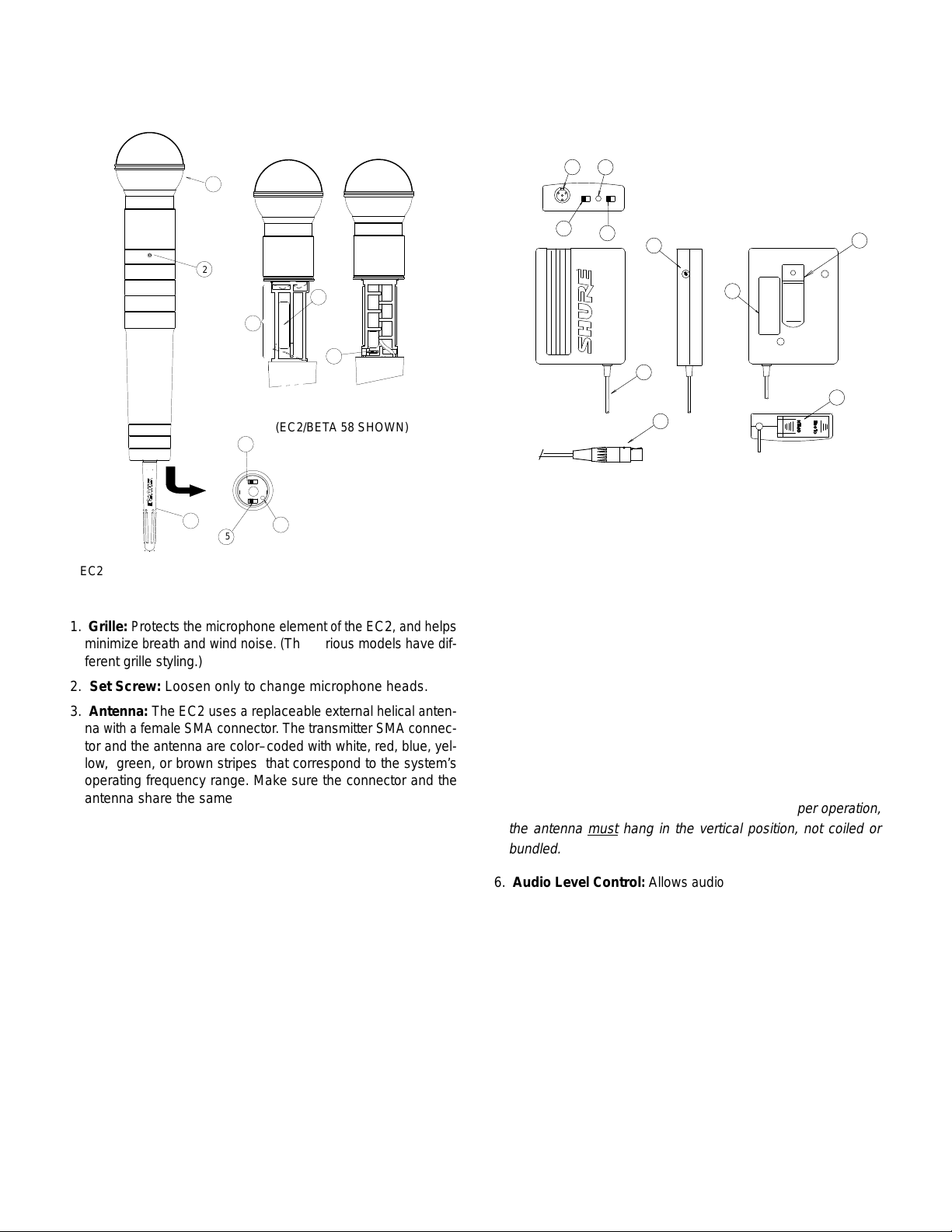
EC2 MICROPHONE–TRANSMITTE
1. Grille: Protect
minimize
g
ferent
2.
Set Screw:
3. Antenna: The EC
with a f
na
tor
and the a
s the m
icrophon
b
reat
h and wind n
rille styling.)
Loosen only to change microphone heads.
2 uses a r
emal
e SMA c
ntenn
a are c
FIGURE
oise
eplaceabl
onnector
olor–code
R F
EATURE
1
e e
lemen
. (The v
. The t
d with w
S A
ND CONTROLS
t o
f the EC2, and h
ariou
s m
e e
xterna
ransmitte
hite
r SMA c
, red, b
odel
l h
s have d
elica
l a
lue
low, green, or brown stripes that correspond to the system’s
operating frequency range. Make sure the connector and the
antenna shar
4. MIC ON/OF
phone
may o
that
vents
the r
5.
POWER ON/OFF Switch: Turns transmitter power on and
w
ithou
e t
he same color code.
F S
lid
e S
witch: Permit
t t
urnin
g the t
ccu
r when the m
eceive
r from p
ransmitte
icrophon
ickin
g up u
s user t
o “
mute
r off. This a
e i
s t
urne
d o
void
n o
nwanted signals.
” the m
s the “
r off and p
off.
6.
Battery Test Light: Illuminates when the POWER switch is
turned
o
n and a “
not
i
lluminate
7. Battery Compartment:
good
, the t
” b
atter
y is i
nstalled
. When this l
ransmitter wil
l n
ot work.
Unscrewing the handle and sliding it
igh
downward exposes the battery compartment and the audio
GAIN Switch (9).
8. Frequency Identification Label:
compartment,
ing frequency
this label lists the transmitter’s original operat
.
9. Audio HI/LO GAIN Switch:
Located inside the battery
Controls audio level of the
phone.
elps
nten-
onnec-
, y
el-
icropop”
re-
t d
oes
micro
1. INPUT Jack:
adapter
2.
Battery Test Light: Illuminates when the POWER switch is
if-
turned on and a “good” battery is installed. If this light does not
on, the t
turn
3.
MICROPHONE ON/OFF Switch: “Mutes” the microphone
without
4.
POWER ON/OFF Switch: T
5.
Antenna: A flexible antenna wire is permanently attached to
the
b
otto
the antenna must
The microphone cable or the W
cable plugs into this connector
t
urnin
ransmitter wil
g the t
l n
ransmitte
ot work.
r o
ff, s
o n
urns transmitter on and of
m o
f the b
ody-pac
k t
ransmitter
hang in the vertical position, not coiled or
A300 instrument
.
o “
pop” sounds occur.
.
Fo
r p
rope
r o
f.
peration,
bundled.
-
-
6. Audi
7.
8. Belt Clip:
9. TA4F
10.
o L
eve
l C
s
oun
ous
d s
justments (se
ontrol: Allow
ources
. A s
e page 5
mal
).
s a
udi
l s
crewdrive
o l
eve
r i
l a
djustment
s s
upplie
s for v
d t
o make a
ari-
Frequency Identification Label: This label identifies the
transmitter’s
original operating frequency
Allows the transmitter to be worn on
band
or guitar strap. It can be removed, if desired.
Microphone Cable Connector:
jack
on the body-pack transmitter
.
a belt, waist
Plugs into 4–pin input
.
Battery Compartment: Hinged cover on bottom surface
exposes
the battery compartment.
d-
-
2
Page 3

EC
4 R
ECEIVER CONTROLS AND INDICATORS
(FIGUR
1.
2. DIVERSIT
E 3)
2
1
7
EC4
RECEIVER FEA
9
TURES AND CONTROLS
FIGURE 3
43
108
6
5
POWER ON Indicator: This green light glows when the
POWER
button is turned on.
Y S
igna
l I
ndicators: Yellow ligh
s glow t
o show u
able RF signals from antenna A, antenna B, or both. Normal
operation
these lights are
flickering
3. AUDIO NORMAL Indicator:
ly
4.
AUDIO PEAK Indicator: This light glows red to show ap-
is i
ndicate
d when e
not
l
ights may indicat
indicators of signal
ithe
r o
e m
arginally acceptable signals.
This green light flashes regular
to show normal audio operation.
r both l
ight
s g
strength
low
. Note t
, but barely
proaching audio overload condition. Normal operation will
cause
o
ccasiona
l f
lashin
g o
f this l
igh
t on loud s
ignals
; c
onstant
glowing indicates excessive audio level and need to lower
transmitter
5. VOLUME Rotary Control:
A
udio Gain switc
h o
r rotary control.
Determines signal level at both re
ceiver OUTPUT connectors.
6. POWE
7.
8.
R O
n/Of
f B
put
jack t
o the r
and remains o
utton: Applie
eceive
r c
n when p
ircuitry
owe
r i
s p
ower fro
. The g
s applie
m the D
ree
n P
d to the r
OWE
C p
R l
ight glows
eceiver.
owe
ANTENNA Connectors: UHF type connectors provide con-
nection
t
the
to th
c
oaxia
e o
o 1/4-wav
ptiona
l c
abl
e v
e i
n the o
l 1/2-wav
ertica
e h
l a
ntenna
ptiona
igh-gai
s s
upplie
l W
A42
0 A
n a
ntenn
ntennas (WA380).
d with the EC4, t
a C
abl
e Kit, o
12 VDC Negative Ground Coaxial POWER Jack: Accepts
power from the supplied ac adapter, or from any well filtered
12.5
to 1
8 V
dc (20
0 mA) p
9.
SQUELCH Screwdriver Control: Automatically quiets or
ower supply.
“mutes” the receiver when no transmitter signal is received.
This control is factory-set for optimum operation in most
applications,
the
“EC4
10.
OUTPUT Connectors: XLR connector provides balanced low
but can be adjusted for unusual conditions. See
Receiver Squelch Control Adjustment” paragraph.
impedance microphone-level output; 1/4-inch phone jack provides
u
nbalance
d a
uxiliar
y l
eve
l o
utpu
t t
o a
udi
o m
ixe
r o
r a
mplifier.
PRE-INSTALLATION REQUIREMENTS
Before
tem,
• A
attempting to install the EC wireless microphone sys
make sure you have the following items:
9V alkaline battery for the transmitter (Duracell MN1604 or
equivalent).
(NiCad)
A r
echargeable
b
attery may als
, h
o be u
eav
y duty 8.4V n
sed.
ickel-cadmium
• A microphone for the EC1 transmitter—either one designed
specifically for the transmitter (such as a Shure WL84 or
or a low impedance dynamic microphone
WL93),
with a micro
7
r i
hat
phone
adapter cable W
to
the electrical output of
cable
such as the Shure W
A310. If the system is to be connected
a musical instrument, an instrument
A302 must be used.
IMPORTANT: Other manufacturer’s microphones specified for
wireless use are generally
not
compatible, as supplied, with
Shure wireless systems.
• A receiver-to-mixer cable with a 3-pin XLR connector (for bal -
m
anced
cuit phon
receiver
EC
4 R
1. Plac
ceiver
and othe
2. If the r
icrophon
e plug on one end (for u
o
ECEIVER SETUP AND CONNECTIONS
e the r
near R
r d
eceiver is p
adhesive bumper
s-
receiver is to be rack mounted, remove the screws on each
side
of the r
the holes, and secure the brackets with the two removed
screws
and the t
3. Plu
g the A
-
the receiver.
4. Plug the A
5. Attac
h the s
nectors on the receiver. Make sure they are pointing up and
are
w
ithi
flecting
6. Attac
-
1
n the line o
o
h the a
/4-inch phone plug on the receiver end between the desired
EC4 OUTPUT connecto
n-
IMPORT ANT: Improved diversity receiver performance may be
obtained by remotely locating one or
are
s
eparate
WA380
o
r
1/2-Wav
application.
They may b
WA420 Antenn
both
a
ntenna
of th
e rack u
operate
u
p to four r
WA404 amplifie
T
ransmitter Battery Selection
Only
two types of batteries are
EC1
and EC2 transmitters:
•
9V
alkaline batteries (Duracell MN1604 or equivalent).A fresh
9V
alkaline battery should provide 7 hours of operation.
•Rechargeable,
. N
iCa
ies
IMPORTANT: Use
chargeable 8.4V NiCad battery. Carbon–zinc and zinc-chloride
batteries will not provide sufficient power for proper operation,
and
EC1 TRANSMITTER SETUP
EC1 T
1.
With the transmitter POWER ON/OFF switch in
tion,
-
OPEN
d b
are not recommended.
ransmitter Battery Installation
slide
arrow until the cover pivots open. See Figure 4 below
e l
eve
l EC4 r
eceive
r o
utput)
, o
r 1
/4-inc
h 2
-cir-
utput)
eceive
igita
eceive
, and a m
r i
n its o
F n
ois
e s
l d
evices (e.g., C
lace
s t
o the b
r c
ixe
r i
nput connecto
perating position
ource
s such a
d o
n a h
orizonta
otto
ase
, p
ositio
nbalance
D p
m c
n the m
s l
igh
layers an
l s
urface
orner
s o
ountin
d a
. A
t d
uxiliar
r o
n the o
voi
d p
immers
d d
, a
f the r
g b
y l
lacin
, c
igita
l d
ttac
eceiver
racket
eve
l E
ther.
g the r
omputers
elays).
h the f
our
. I
f t
s o
ver
wo supplied screws.
C a
dapte
r into the P
C a
dapte
r into a 1
upplie
d 1/4-wave antenna
f s
bjects wil
udi
d b
y 1.5 m
e H
l d
o c
onnectin
igh-Gai
eter
igh
egrade syste
e r
a C
abl
e K
b
e r
hur
its
emotel
s
sin
must
g the S
eceiver
d A
ntenna/DC Power Distributio
OWE
R jack o
20V
, 6
0 H
t o
f the t
ransmitter
m p
g c
abl
e with a
r and the m
s (60 i
n A
ntenna
emotel
. If the r
y l
e W
A44
ixe
b
oth antennas so tha
nches
) o
s are r
y l
ocate
eceive
ocate
d o
0 a
ccessor
s with only two a
n the rear p
z power source.
s t
o the A
NTENN
. O
bstruction
erformance.
n XLR c
r or a
r m
ore
onnecto
mplifie
. O
ptiona
ecommende
d u
sin
g one o
r i
s t
o b
e rack m
r m
ounte
d o
y r
ack-moun
ntennas
, use the S
n S
ystem.
ane
A c
s or r
r i
nput.
l S
d for t
r two S
ounted,
n the f
t kit. T
on-
r or a
t t
hey
hure
hure
ront
hure
recommended for use with the
h
eav
atterie
y duty 8.4V n
s w
ill only provid
only a 9
V a
ickel-cadmiu
e 1.5 t
lkalin
e b
o 2 h
attery o
m (
our
r a h
NiCad
) b
s o
f o
peration.
eavy-duty
atter-
, r
the OFF posi
the battery compartment access cover toward the
C4
he
l o
his
e-
f
e-
o
e-
.
3
Page 4

2.
Insert a new 9V alkaline battery into the battery compartment.
Observe
Checking
To
proper battery polarity (“+” and “–”).
PRESS HERE AND SLIDE
COVER BACK T
9V
ALKALINE
BATTERY
EC1 BATTER
the EC1 T
ransmitter Battery
Y I
NSTALLATION
FIGURE 4
check the battery in the EC1 transmitter
O OPEN
, turn the transmit
-
ter POWER switch on and observe the Battery Test light. It
should
be bright and clearly visible, indicating adequate voltage.
If
the light is dim, the battery voltage has dropped below 6.5 volts
and
the battery should be replaced
Cad only). If the light does not turn on, the transmitter will not op
erate
and the battery should be replaced.
(9V alkaline or recharged Ni
-
-
Microphone Connections
1.
Plug the lavalier microphone cable or the W
adapter
cable into the 4-pin connector on the EC1.
2.
If you are using a lavalier microphone, press the microphone
into
the necktie mounting block and clip it to your tie or lapel. If
you
are using an electric instrument, plug the W
ment
adapter cable into you guitar or instrument.
TRANSMITTER
W
A310 MICROPHONE
ADAPTER CABLE
132
W
A302 INSTRUMENT
ADAPTER CABLE
TIP
SLEEVE
EC1
TRANSMITTER CABLE CONNECTIONS
EC1
INPUT CONNECT
3
1
4
2
BLACK
1 – GROUND
OR
2 – +5 VDC
3 – AUDIO (FOR DYNAMIC
MICS OR INSTRUMENTS)
4 – 20K T
PLUG SHOR
FOR CONDENSER MICS)
3
4
910K
FIGURE 5
A302 instrument
O GROUND (MA
TS T
1
2
1
3
4
2
A302
TING
O PIN 3
instru
-
Any Shure wireless lavalier microphone or accessory cable
with
a Switchcraft T
rectly
into
the transmitter input connector
microphones
A4F type 4-pin (female) connector plugs di
. Many other condenser
will operate using the transmitter’s regulated +5
-
V
DC power on pin 2. Low impedance dynamic or ribbon microphones with pin 2 output can be used with the optional WA310
adapter
NOTE: Phantom powered condenser microphones will not nor
mally
cable. See Figure 5.
operate with the EC1/W
A310 transmitter configuration
-
.
EC1 Audio Gain Adjustment
The EC1 transmitter audio gain has been factory set to pro-
vide
a typical level. However
singing or loud musical
, for SPL applications such as loud
instruments,
the preset audio gain level
on the EC1 transmitter may be too high, as indicated by the
steady glow of the red AUDIO PEAK light on the EC4 receiver
when
an RF signal is present.
For low SPL applications, such as soft-spoken presenters,
the
audio gain setting may need to be increased, as indicated by
the
failure of the AUDIO PEAK light to turn on when an audio
nal
is present.
I
f n
ecessary
1. For High SPL Applications
turn
wise
played.
2. For Low SPL
, a
djus
t the a
udi
o gain on the EC1 a
s follows:
: Using the supplied screwdriver
the
MIC LEVEL control on the transmitter counterclock
while the vocalist is speaking or an instrument is being
See Figure 6.
Applications:
Using the supplied screwdriver
sig
turn the MIC LEVEL control on the transmitter clockwise until
the
red AUDIO PEAK indicator
sionally
NOTE: Whe
mitter
while the microphone is in use. Refer to Figure 6.
SCREWDRIVER
(SUPPLIED)
EC1
BODY
TRANSMITTER
-PACK
EC1
n the EC4 r
i
s OFF, the a
udio mixe
AUDIO
AUDIO GAIN ADJUSTMENT
eceive
on the receiver flickers occa
LEVEL CONTROL
FIGURE 6
r i
s ON and the EC1 o
r gain s
houl
d b
e t
urne
LOW
HIGH
d d
r EC2 t
own
rans-
, s
ince
the receiver can receive signals from other sources. If the mixer
controls
are not a
ccessible
, turn the r
eceive
r v
olum
e d
own when
the transmitter is not in use to prevent unwanted signal pickup.
The
t
side
i
ransmitte
nterference
r may also b
. See the S
e left o
quelc
n (
h C
muted
) t
o g
ontro
uar
l a
djustment paragraph.
d a
gainst out-
EC2 TRANSMITTER SETUP
EC2 T
ransmitter Battery Installation
1. Make sure the transmitter POWER ON/OFF switch is in the
OFF position.
2.
While holding the upper part of the transmitter, unscrew the
lower
handle and slide it downward. as shown in Figure 7.
GRASP
MICROPHONE
HERE
UNSCREW
L
OWER
EC2
BA
AND
HANDL
OPEN
TTER
FIGURE 7
E T
O
Y INST
ALLATION
9V
ALKALINE
BATTERY
(INSER
T “+” SIDE
FIRST
-
,
-
,
-
4
Page 5

3.
Á
Insert a new 9V alkaline battery into the battery compartment.
Observe
proper battery polarity (“+” and “–”). Close the bat
tery compartment after the battery has been installed.
Checking th
To
c
hec
e EC2 T
k the b
ransmitter Battery
atter
y i
n the EC2 t
ransmitter, tur
n the t
ransmitter
POWER switch on and observe the Battery Test light. The light
should
b
e b
righ
t and c
learl
y v
isible
, i
it is dim, the b
battery
s
t d
e b
attery shoul
houl
oes no
the ligh
th
atter
d be r
t glow a
y v
eplace
d be d
oltag
t a
iscarde
e has d
d (
alkalin
ll, th
ndicatin
roppe
e o
e t
ransmitter wil
d o
r recharged.
d b
r r
echarge
g a
elo
dequat
w 6.5 v
d N
l n
ot operat
olt
iCa
e v
oltage
s and t
d o
nly)
e a
. I
he
. I
nd
EC2 Audio Gain Adjustment
The
EC2 audio gain has been factory set in the LO position
for
high sound pressure level (SPL) applications. For low SPL applications,
just
1.
Unscrew the handle and locate the audio GAIN switch adja
2.
With the system ON and the transmitter in use, select either
NOTE:
load
the preset audio gain may be
too low
. If necessary
, ad
the audio gain on the EC2 as follows:
cent
to the battery holder. See Figure 8.
LO
GAIN
HI
GAIN
HI/LO
SWITCH
EC2 AUDIO GAI
the
LO gain or HI gain position so that the receiver’s AUDIO
PEAK
light flickers only occasionally
N A
FIGURE 8
DJUSTMENT
.
Some very loud vocalists may experience audible over
even when the audio GAIN switch is in the LO position. The
EC2 can be easily modified for higher SPL input. For more information,
contact your dealer or the
Shure Service Department.
OPERATING THE SYSTEM
1. T
urn on the transmitter and receiver POWER switches.
2. Make sure the transmitter MIC ON/OFF switch is on.
3.
Talk into the microphone (or play a musical instrument) and
observe
receiver.
the AUDIO PEAK and DIVERSITY lights on the
Normal operation is indicated by:
EC4
• Steady glow of one or both DIVERSITY lights on the EC4
receiver (indicates good RF signal).
•Steady
AUDIO signal).
• Occasional
4.
Continue talking or playing into the microphone and move
around
ceiver
yellow
or
when
change
glow
or flashing AUDIO NORM light (indicates good
flashing of the red AUDIO PEAK light.
the performing
area. At each location, observe the re
display and make sure the RF signal is adequate. If the
DIVERSITY lights flicker
the W
A380 antennas. The audio level should only change
, reposition the EC4
receiver
the loudness of the audio source changes; it should not
when the microphone is moved
around the perform
-
also
uncover locations that are prone to audio feedback.
IMPORTANT:
and
can present a variety of problems.
formance
Every
without
wireless microphone installation is unique,
Never
a “walkthrough” first. If major changes (equip
attempt a live per
ment, scenery, etc.) have been made since the walk-through,
ing area. Checking microphone operation in this manner will
check the wireless microphone operation again—as close to
f
performance
EC
f
4 R
The
and does not normally
ting
needs to be
equipment
tion
site, proceed as follows:
1. Plac
-
during
2. Turn off the t
-
3.
Turn the receiver VOLUME control full counterclockwise and
turn
4.
Observe the lights on the receiver
time as possible.
eceiver Squelch Control Adjustment
SQUELCH control is preset for most operating conditions
require readjustment. However
changed to compensate for the ef
in the system or for the RF conditions at the installa
e the w
ireles
s s
yste
m i
n the l
ocatio
n w
a p
erformance.
her
ransmitter POWER switch.
the P
OWER switc
h o
n.
front panel. If the DIVERSI
TY A or B, AUDIO NORM, or PEAK lights are glowing, the
SQUELCH control needs to be readjusted. Slowly turn the
SQUELCH
tinue
control clockwise until all the lights turn of
turning the SQUELCH control slightly
past this point.
NOTE: Turning the SQUELCH control clockwise will prevent
unwanted signal
when
the m
decrease the system’s operatin
5. To r
etur
n the S
back
to the m
EC
4 R
eceiver Volum
s and n
icrophon
QUELC
idrang
e (
e C
e s
H c
ontrol
ois
e from o
igna
l i
ontro
straigh
s not p
g r
ange.
l t
o the f
t up) p
verridin
resent
actory setting
osition.
g the s
, but will e
The VOLUME control on the EC4 receiver affects both out-
puts
on the rear panel. This control can be adjusted to make the
system output identical to that of a conventional wired microphone, avoiding extreme differences in mixer input level settings.
T
-
urning the VOLUME control counterclockwise decreases
the
output level; turning it clockwise increases output.
Changing Operatin
g F
requency
The carrier frequency of any EC Series transmitter and receiver may be changed by a factory-authorized technician.
Please
contact your local dealer
Shure
Service Department for details. The modifications
factory
training and cannot be made by the end user
Controlling Multipath T
, sound system contractor
ransmission
Multipath transmission (or “dropout”) occurs when the
RF
signal and a reflected signal arrive at the receiver at dif
times
or out of phase, or when the
structed.
To
The result is excessive
avoid this phenomenon, observe the following precautions:
signal path is completely ob
noise or temporary signal loss.
• Maintain line-of-sight transmission. Ideally, the transmitter
should always be
user
antennas.
•Keep
-
the distance between the transmitter and the receiver
as short as possible.
tennas
•Avoid
operating the wireless microphone around reflective sur
especially metal surfaces.
faces,
able to see at least one of the receiver
• Make sure both transmitter and receiver antennas are posi-
-
tioned vertically.
, if this set
fects of other
e i
t will b
e u
f. Con
quelc
h c
ffectively
, r
otat
, or the
require
.
direct
sed
ircuit
e i
ferent
an
-
-
-
-
-
-
t
-
-
-
5
Page 6

TROUBLESHOOTING
If
the i
nstallatio
n and s
etu
p i
nstruction
s have been f
ollowe
d a
nd
a problem still exists, perform the troubleshooting procedures in
the tabl
Shure
S
e b
ervic
elow
. I
f the p
e D
epartment.
roble
m p
ersists
, c
ontac
t your d
eale
r o
r t
he
PROBLEM
No receiver sound;
neither DIVERSITY
light on receiver is
glowing
No receiver sound;
one or both DIVER-
lights are glow
SITY
ing
Make sur
Check transmitte
e P
OWER switc
r b
attery an
h on t
d r
ransmitte
eceive
Check receiver squelch setting.
r a
Check receive
Make sur
Make sur
transmitte
With
the microphone POWER switch ON, turn up the receiver volume control.
Make sure transmitter MIC switch is ON.
-
Check transmitter microphone MUTE switch.
ntenna connections.
e t
ransmitte
e t
ransmitte
r and the r
r and r
eceive
r and r
eceive
eceiver. Highe
r are o
r a
r gain a
Make sure microphone cable plug is locked into transmitter connector
Check connection between receiver and microphone mixer
Talk
into the microphone and observe the receiver AUDIO light. If the light
in sound system.
Noise from receiver
with transmitte
VERSITY
glow o
ceiver
l
ight
r off; D
s on r
r f
licker
Received signal is
noisy or contains extraneous sounds with
transmitte
r o
n
Look
for strong local interference sources such as other radio signals. (Nearby motors
I-
could
e-
also be the problem.) Reposition antennas.
SQUELCH control may be set too low
Look
for strong local interference sources such as other radio signals, nearby motors or lighting equipment.
Remove the source of interference, reposition the receiver
T
wo transmitters may be operating on the same frequency
Signal ma
high
y b
gain a
ntennas (WA380
e too w
eak. Repositio
) and a
n a
ntenna cable ki
SQUELCH control may be set too low
SPECIFICATIONS
OVERALL SYSTEM
RF Carrier Frequency Range
169.445 MHz to 216.100 MHz
Frequency Stability
±
32.5 ppm, ±5.5 kHz (Complies with FCC regulations)
W
orking Range
600 feet (182.8 m) at 50 mW
Modulation
±15
kHz deviation compressor-expander system with pre- and
de-emphasis
Harmonic Distortion (ref. ±15 kHz deviation, 1 kHz modu
Total
lation)
0.4%
typical, 0.7% maximum
Dynamic Range
>102 dB A-weighted
Audio Frequency Response
80 to 15,000 Hz, ±2 dB (NOTE: Overall system response depends
on microphone element; refer to microphone frequency
response
Operating T
–4°
to 122° F (–20° to 50
EC4 RECEIVER
RF Sensitivity
0.45 µV for 12 dB SINAD typical
Image Rejection
90 dB typical
Spurious Rejection
80 dB typical
Ultimate Quieting
>94 dB A-weighted
Squelch Quieting
>94 dB A-weighted
(average conditions)
curves on page 8)
emperature Range
° C)
(reference 15 kHz deviation)
(reference 15 kHz deviation)
SOLUTION
r and r
eceive
r i
s ON (Bot
r p
ower source.
n sam
e o
peratin
g f
ntennas follow lin
e o
f sight
ntennas (WA380
. Readjust as necessary.
ntennas
. I
f p
ossible
t (
WA420
, move them c
. Readjust as necessary.
Squelch Threshold
2.0 µV
preset, adjustable from 2.0 t
Output
dBV, 1 kΩ output impedance, unbalanced; –18 dBV
–2
output impedance, balanced (volume full clockwise; full devi-
unloaded)
ation;
Antenna Input Impedance
50Ω
nominal
Antenna
Plastic sheathed stainless steel,
PL-259 UHF connectors
Power Requirements
-
12.5 to 18 VDC (negative ground), 200 mA;120 Vac, 60 Hz
Model PS20 external AC adapter supplied (Model PS20E
220/240
V
Overall Dimensions
1.75 in. H x 17.125 in. W x 7.87 in. D
(44.5 mm x 435 mm x 200 mm)
Includes front panel controls and rear panel UHF connectors;
does not include antennas or rack ears
Weight
4.32 lbs (1.962 kilograms)
Certification
Complies with FCC Part 15 (FCC ID: DD4L4)
Power supply UL listed, CSA listed as Certified
Conforms to European Union Directives, eligible to bear CE
marking; meets European EMC Immunity Requirements (EN
50 082-1, 1992); ESD (IEC 801-2); RF radiated (IEC 801-3);
EFT
(IEC 801-4).
EC1 BODY–PACK TRANSMITTER
RF Power Output
50 mW maximum
Modulation
FM
(40K0F3E, FCC Part 90, FCC Part 74) ±15 kHz
62 µ
sec pre–emphasis
h g
ree
n L
EDs ar
e i
lluminated).
requency.
. If n
) m
ay b
ecessary
e r
equired.
, r
educ
e the d
.
.
is glowing, the problem is elsewhere
or lighting equipment
, or reposition the antennas.
. Locate and turn one of
lose
r t
) are a
vailable
o the t
f.
ransmitter
ο 50 µV
1
/4 wavelength, 428 mm,
ac, 50/60 Hz available optional)
istanc
. O
e b
ptiona
etwee
n t
l 1/2 w
, 150
deviation,
he
ave
Ω
6
Page 7
Audio Gain Adjustment Range
40 dB
Input Impedance
Actual: 17 kΩ, pin 4 wired to pin 3 for WL93 or other wireless
condenser
phone
microphone; 100 kΩ, pin 4 open for dynamic
or instrument pickup
micro
Power Requirements
Battery Type: 9 volt a
lkalin
e (
Duracel
l 1604 o
r e
quivalent)
8.4-volt nicad optional
Battery Life: 7 hours minimum (alkaline)
1.5 to 2 hours typical (nicad, per charge)
Current Drain: 55 mA typical
Antenna
Attached, 15.2 in. (386 mm), flexible wire
Modulation Limiter
Internal compressor
Audio Polarity
EC1 Transmitter with Shure W
Positive
voltage
and
pressure on microphone diaphragm produces positive
on pin 2 with respect to pin 3 of low-impedance output,
on tip with respect to ground of aux output.
EC1 Transmitter with W
Positive
voltage applied to tip of W
of WA310 XLR connector results
respect
to
to pin 3 of low-impedance output or on trip with respect
ground of aux output.
Dimensions (excluding antenna and belt clip
82.6 mm High x 63.5 mm
(31/
in.
x 21/
4
in. x 11/32 in.)
2.
ireless Microphones:
A302 or W
A310 Cable:
A302 phone plug or
in positive voltage at pin 2 with
)
Wide x 26.2 mm Deep
to pin 3
Weight
Without Battery: 96.4 g (3.4 oz)
With Battery: 142 g (5 oz)
Certification
Complies with FCC Parts 74 and 90 (FCC ID: DD4L1
1)
Conforms to European Union Directives, eligible to bear CE
marking; meets European EMC Immunity Requirements (EN
50 082-1, 1992); ESD (IEC 801-2); RF radiated (IEC 801-3);
EFT
(IEC 801-4).
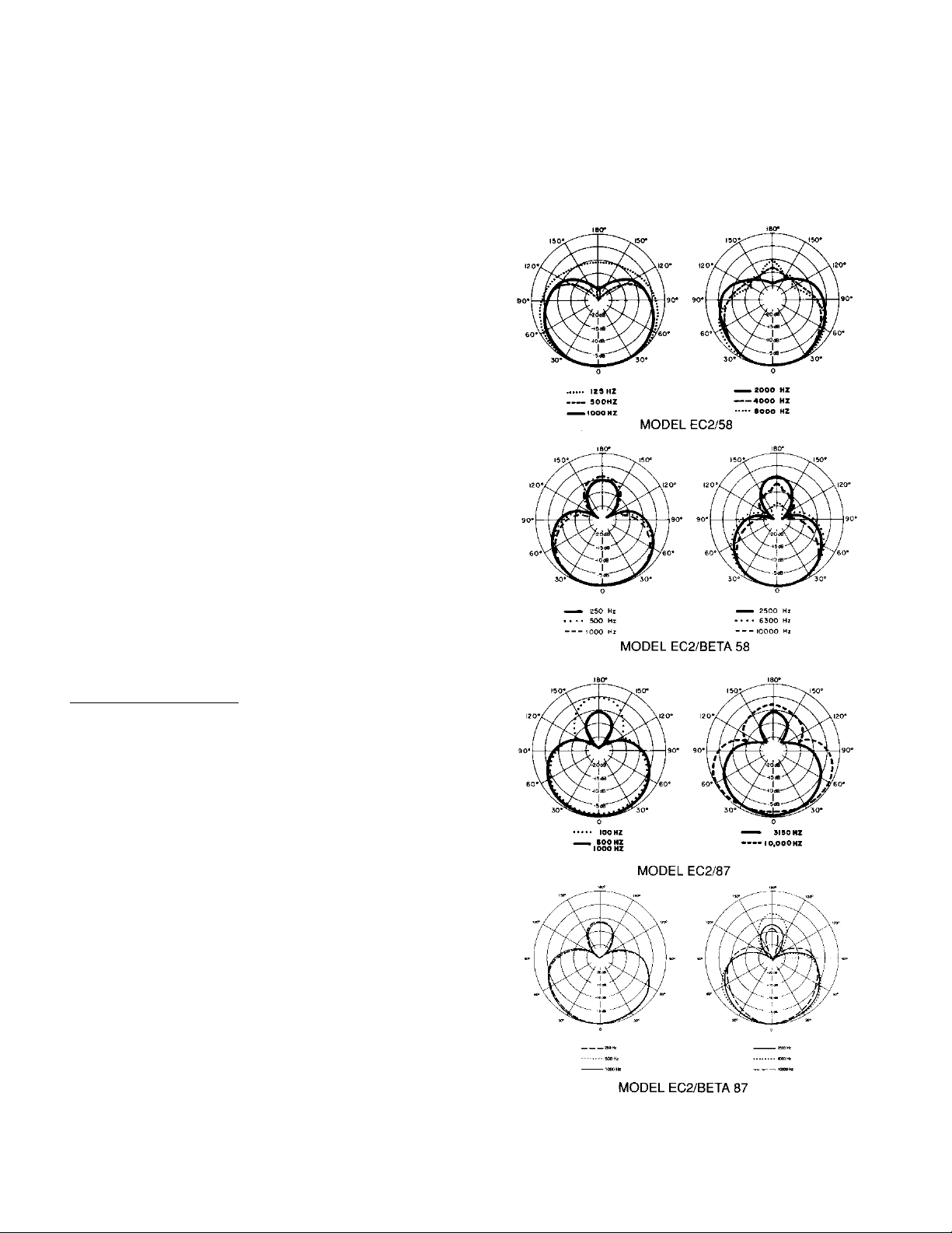
EC2 Polar Patterns (See Figure 10)
Uniform with frequency
Cardioid (EC2/58)
Supercardioid (EC2/Beta 58, EC2/87, EC2/Beta 87)
-
, symmetrical about axis
EC2 TRANSMITTER
RF Power Output
50 mW maximum
Modulation
FM (60K0F3E) ±15 kHz deviation, 62
µs pre-emphasis
Modulation Limiter
Internal compressor
Audio Polarity
Positive
pressure on microphone diaphragm produces positive
voltage on tip (with respect to ground) of unbalanced output,
and
on pin 2 (with respect to pin 3) of balanced output
Audio Gain Adjustment Range
15 dB (2-position switch); additional –6 dB internal pad
Antenna
Removable,
or-keyed
to transmitter frequency range).
external 1/4-wave helical antenna
(antenna is col
Power Requirements
Battery T
ype: 9 volt a
lkalin
e (
Duracel
l M
N160
4 o
r e
quivalent)
8.4-volt nicad optional
Battery Life: 7 hours minimum (alkaline)
1.5 to 2 hours typical (nicad, per charge)
Current Drain: 55 mA typical
EC2 T
ransducer T
ype
EC2/58, EC2/Beta 58: Dynamic
EC2/87, EC2/Beta 87: Electret bias condenser
-
TYPICAL POLAR PATTERNS
FIGURE 10
7
Page 8

EC
2 F
requenc
Frequency
at
a d
istanc
y R
espons
r
espons
e of 0.6 m
e c
eters (
e (See F
urve
s b
elo
w were m
2 f
eet
igur
e 1
1)
easure
) from t
he sound source.
d i
n a free f
ield
Weight
Model Without
EC2/58
EC2/Beta 58
EC2/87
EC2/Beta 87
453.6 g (16.0 oz) 496.1 g (17.5 oz)
337.2 g (1
337.2 g (1
Battery
41
1.1 g(14.5 oz )
1.9 oz)
1.9 oz)
W
ith Battery
453.6 g (16.0 oz)
382.7 g (13.4 oz)
382.7 g (13.4 oz)
Certification
Complies
with FCC Parts 74 and 90 (FCC ID: DD4L2)
Conforms to European Union Directives, eligible to bear CE
marking; meets European EMC Immunity Requirements (EN
50 082-1, 1992); ESD (IEC 801-2); RF radiated (IEC 801-3);
EFT
(IEC 801-4).
REPLACEMENT PARTS
SM58 Cartridge
Beta
58 Cartridge
SM87
Cartridge R128
SM58
Grille
Beta
58 Grille
SM87
Grille
Beta
87 Cartridge
Beta
87 Grille
EC4
AC Adapter
EC4
1/4-W
∗
Replacement
Shure Distribution Centers.
cartridges for the Beta 87 are available only through factory exchange or through
. . . . . . . . . . . . . . . . . . . . . . . . . . . . . . . . .
. . . . . . . . . . . . . . . . . . . . . . . . . . . . . . .
.
. . . . . . . . . . . . . . . . . . . . . . . . . . . . . . . .
. . . . . . . . . . . . . . . . . . . . . . . . . . . . . . . . .
.
. . . . . . . . . . . . . . . . . . . . . . . . . . . . .
. . . . . . . . . . . . . . . . . . . . . . . . . . . . . . . . . .
. . . . . . . . . . . . . . . . . . . . . . . . . . . . . . .
. . . . . . . . . . . . . . . . . . . . . . . . . . . . . . . .
.
. . . . . . . . .
ave Antenna Assembly
PS20 (120V);PS20E (220/240V)
. . . . . . . . . . . . . . .
R158.
R160.
RK143G.
RK265G
RK277G.
N/A∗.
90B3955.
90C8342.
FURNISHED ACCESSORIES
Rack Panel Bracket (EC4) 48A8012.
Swivel
Adapter (EC2)
Storage
Storage
Bag (EC1)
Bag (EC2)
. . . . . . . . . . . . . . . . . . . . .
. . . . . . . . . . . . . . . . . . . . . . . . .
. . . . . . . . . . . . . . . . . . . . . . . . . . . . .
. . . . . . . . . . . . . . . . . . . . . . . . . . . . .
WA370A.
26A13.
26A14.
OPTIONAL ACCESSORIES
e 4
-Socke
t C
Miniatur
In-Line
Audio Switch (EC1)
1
/2-Wave
Antenna
Antenna (EC4; specify frequency)
Distribution System
Antenna/Power
Antenna
Cable Kit (EC4)
onnector (EC
Distribution System
Antenna Rack Mount Kit (EC4) WA440.
∗∗Includes cable, UHF adapter, and wall–mount bracket.
1 B
ody-Pack) WA330.
. . . . . .
. . . . . . . . . . . . . . . . . . . . .
WA380A/B/C/D.
. . . . . . . . . . . . . . . . . . . .
. . . . . . . . . . . . . .
. . . . . . . . . . . . . . . . . . . . .
WA420∗∗.
. . . . . . . . . . . . . . . . . .
WA360.
WA400.
WA404.
INFORMATION TO THE USER
The EC
4 R
eceive
r c
omplie
s with P
art 15 o
subjec
t t
o the c
onditio
n that this d
EC4 Receiver has been tested and found to comply
The
its
of Part 15 of the FCC Rules. These limits are designed to provide rea
sonable
protection against harmful interference in a residential installa
tion. This equipment generates, uses and can radiate radio frequency
energy
and, if not installed and used in accordance
may cause harmful interference to radio communications. However,
there
is no guarantee that interference will not occur in a particular instal
lation.
If this equipment does cause harmful interference to
vision
reception, which can
and
on, the user
more
of the following measures:
(1
) R
I
ncreas
(2)
ceiver.
(3) Connec
which
the r
) C
(4
CAUTION:
Brothers,
is encouraged to try to correct the interference by one or
eorien
t o
r r
elocat
e the s
eparatio
t the e
o o
r T
V r
t the d
eale
C
hanges or m
oul
d void your a
quipmen
eceive
adi
onsul
Inc. c
evic
be determined by turning the equipment of
e the r
eceivin
n b
etween th
t into an o
r i
s connected.
r or a
n e
xperience
odification
uthorit
f the FCC R
e does not c
g a
ntenna.
e e
quipmen
utle
t o
n a circui
d r
adio/T
s not e
xpressl
y t
o o
perat
ules
. O
armfu
l i
with the lim
radio or tele
adi
ifferen
t from that t
pprove
quipment.
peratio
nterference.
o o
n for h
d b
aus
e h
with the instructions,
t and r
t d
V t
echnicia
y a
e the e
r T
y S
n i
V r
elp.
hure
s
-
-
-
-
f
e-
o
TYPICAL FREQUENCY RESPONSE CURVES
FIGURE 11
Overall Dimensions
(excluding antenna)
EC2/58, EC2/Beta 58: 237 mm x 50.8 mm (9 5/
EC2/87, EC2/Beta 87: 213 mm x 50.8 mm (8 3/
16
8
in
.
in
x 2 in.)
.
x 2 in.)
8
FCC LICENSING INFORMA
M
ode
Shure
Parts
74 and 9
IMPORTANT: Licensing of Shure wireless microphone equip-
is the user’s responsibility, and licensability depends on the
ment
user’s
cy.
Shure
nications
l EC1 and EC2 T
0.
classification and application, and on
strongly urges the user to contact the appropriate telecommu
authority concerning proper licensing.
ransmitter
TION
s are T
ype-Accepte
the selected frequen
d u
nde
r F
CC
-
-
 Loading...