

Page 1
Instruction Manual
for
Phonograph Evaluation Kit
This Stereo Cartridge Analyzer is for use by Qualified Factory Trained personnel only.
Manufactured by
SHURE BROTHERS INCORPORATED
222 Hartrey Avenue
Evanston, Illinois 60204
Copyright
27A1347
1979,
(SH)
Shure Brothers
Inc.
Printed
in
U.S.A.
Page 2
I
.
Introduction
TABLE OF CONTENTS
PAGE
............................................................
2
II
.
Equipment Checklist
Ill
.
Electronic Equipment Setup and Check
.....................................................
.....................................
TESTING OF CUSTOMER'S SYSTEM
Cleaning and Inspection of the Stylus Tip
Connection of Customer's Equipment
Turntable Speed
Tracking Force and Antiskating Force Adjustment
Channel Orientation. Crosstalk. and Balance Tests
Phase Check
Antiskating Force and Tracking Force Explanation
Antiskating and Tracking Force Optimization using the Trackability Test
Checking Wear of the Shure TTR-103 and TTR-109 11
........................................................
...........................................................
...................................
.......................................
............................
...........................
...........................
.........
............................
2
3
4
5
5
5
6
7
7
8
ADDENDA
Model C/PEK-3/T 12
Guarantee 12
Shipping Instructions 12
Circuit Diagram and Parts List
...............................................................
........................................................
......................................................
...............................................
13
Page 3
I.
INTRODUCTION
The Shure Model C/PEK-3 Phonograph Evaluation Kit is designed for use with
stereo magnetic phonograph cartridges. The
the
stereo
capabilities of discrete quadriphonic phonograph cartridges. Note
C/PEK-3 may also be used to test
that (1) the quadriphonic properties of these cartridges must be evaluated
through listening tests, and
(2)
stylus wear may be more critical in discrete quad-
riphonic cartridges; moderate wear that yields acceptable stereo playback may
seriously affect discrete quadriphonic playback.
II.
EQUIPMENT CHECKLIST
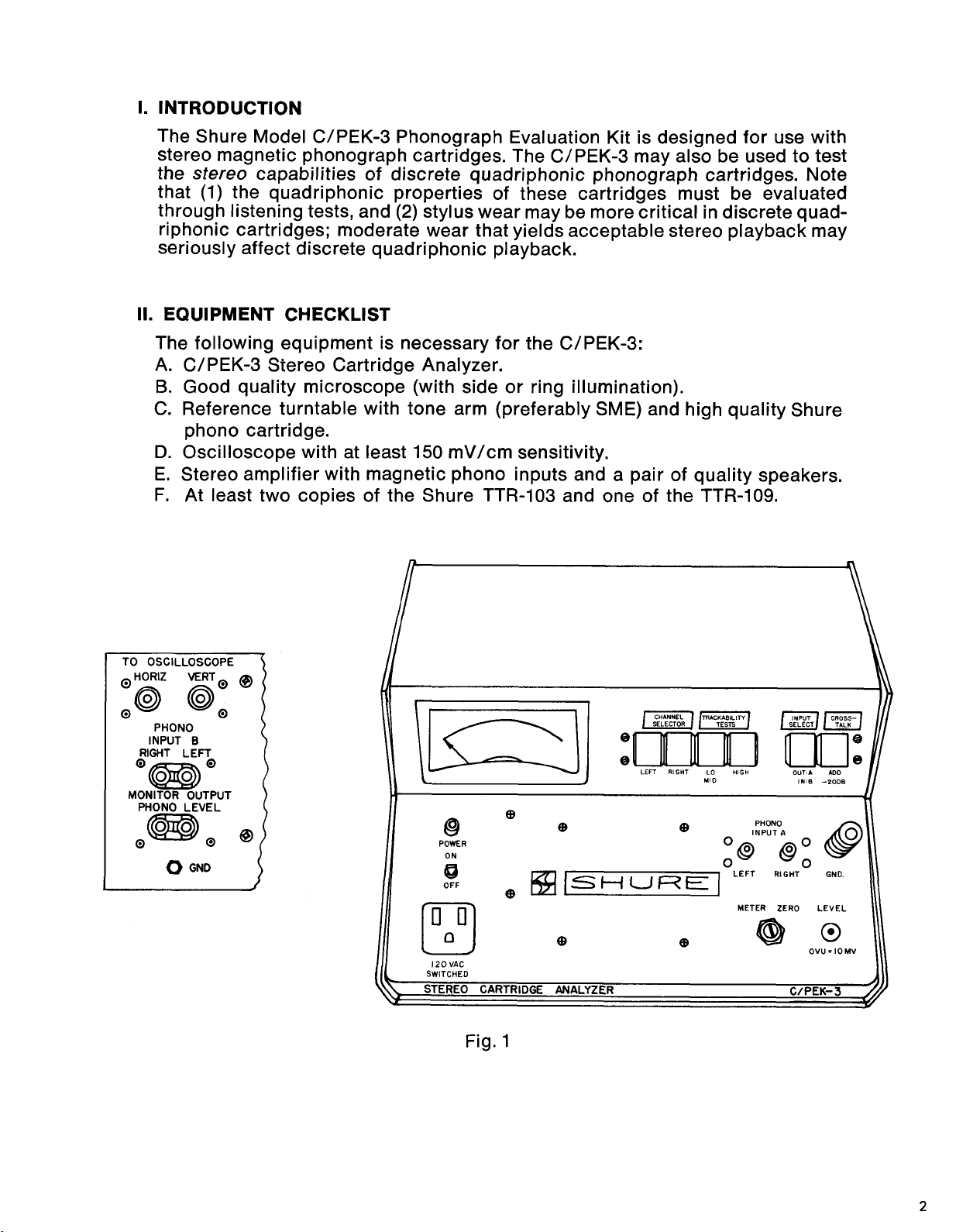
The following equipment is necessary for the C/PEK-3:
A. C/PEK-3 Stereo Cartridge Analyzer.
B.
Good quality microscope (with side or ring illumination).
C.
Reference turntable with tone arm (preferably SME) and high quality Shure
phono cartridge.
D.
Oscilloscope with at least 150 mV/cm sensitivity.
E. Stereo amplifier with magnetic phono inputs and a pair of quality speakers.
F.
At least two copies of the Shure TTR-103 and one of the TTR-109.
I
TO OSCILLOSCOPE
111
POWER
120
Q
ON
8
OFF
VAC
e
tB
Fig. 1
e
Q
e
LEFT
ull!1
RIGHT
e
d
LO
HIGH
MI0
INPUT
0
0
LEFT RIGHT
METER ZERO LEVEL
OUT A ADD
IN
A
0 -ZODB
GND.
Page 4
,
GROUND
IGHT
LEFT
,
&I
-
-
INTEGRATED
STEREO
AMPLIFIER
---I
7
SPEAKER
u
SPEAKER
I
11
\
dL
REFERENCE
TURNTABLE
I
'B"
INPUTS
TEST PANEL
VERTICAL
i
<:;r
-
---A
HORIZONTAL
I
SCOPE
I
I
I
I
lL
MONITOR
OUTPUTS
Pl
I
/---
I'
I
\
1
\
---/
I
I
L
-
-
-
-
CUSTOMER'S
TURNTABLE
OSCILLOSCOPE
0
0
-:-I
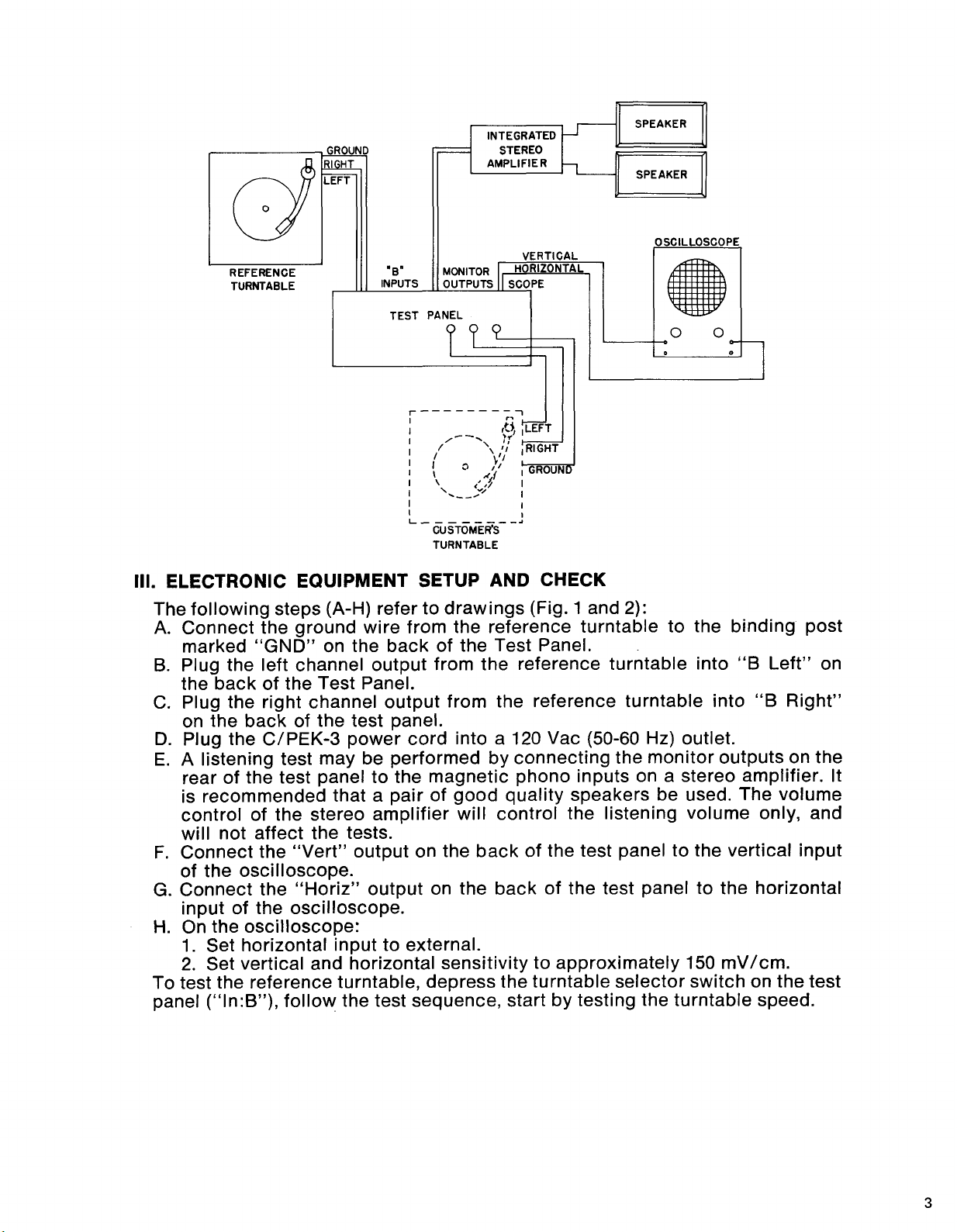
Ill. ELECTRONIC EQUIPMENT SETUP AND CHECK
The following steps (A-H) refer to drawings (Fig. 1 and 2):
A. Connect the ground wire from the reference turntable to the binding post
marked
"GND"
on the back of the Test Panel.
B. Plug the left channel output from the reference turntable into "B Left" on
the back of the Test Panel.
C. Plug the right channel output from the reference turntable into "B Right"
on the back of the test panel.
D.
Plug the C/PEK-3 power cord into a 120 Vac (50-60 Hz) outlet.
E. A listening test may be performed by connecting the monitor outputs on the
rear of the test panel to the magnetic phono inputs on a stereo amplifier. It
is recommended that a pair of good quality speakers be used. The volume
control of the stereo amplifier will control the listening volume only, and
will not affect the tests.
F.
Connect the "Vert" output on the back of the test panel to the vertical input
of the oscilloscope.
G.
Connect the "Horiz" output on the back of the test panel to the horizontal
input of the oscilloscope.
H.
On the oscilloscope:
1.
Set horizontal input to external.
2.
Set vertical and horizontal sensitivity to approximately 150 mV/cm.
To test the reference turntable, depress the turntable selector switch on the test
panel
("ln:B"), follow the test sequence, start by testing the turntable speed.
Page 5
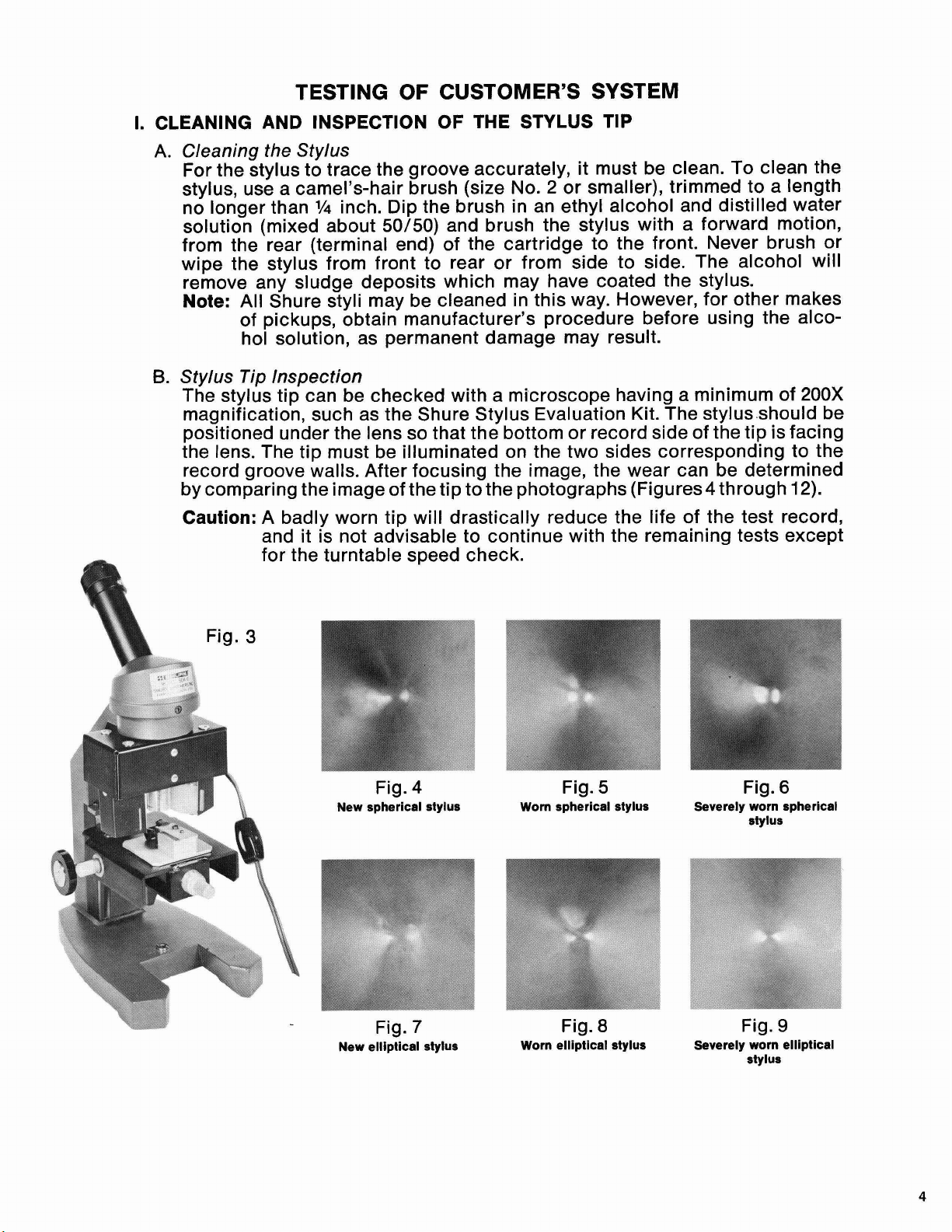
TESTING OF CUSTOMER'S SYSTEM
I.
CLEANING AND INSPECTION OF THE STYLUS TIP
A.
Cleaning the Stylus
For the stylus to trace the groove accurately, it must be clean. To clean the
stylus, use a camel's-hair brush (size No. 2 or smaller), trimmed to a length
lh
no longer than
solution (mixed about 50150) and brush the stylus with a forward motion,
from the rear (terminal end) of the cartridge to the front. Never brush or
wipe the stylus from front to rear or from side to side. The alcohol will
remove any sludge deposits which may have coated the stylus.
Note:
All Shure styli may be cleaned in this way. However, for other makes
of pickups, obtain manufacturer's procedure before using the alco-
hol solution, as permanent damage may result.
B.
Stylus Tip Inspection
The stylus tip can be checked with a microscope having a minimum of 200X
magnification, such as the Shure Stylus Evaluation Kit. The stylus should be
positioned under the lens so that the bottom or record side of the tip is facing
the lens. The tip must be illuminated on the two sides corresponding to the
record groove walls. After focusing the image, the wear can be determined
by comparing the image of the tip to the photographs (Figures4 through 12).
inch. Dip the brush in an ethyl alcohol and distilled water
Caution:
A badly worn tip will drastically reduce the life of the test record,
and it is not advisable to continue with the remaining tests except
le turntable speed check.
4
Fig.
New spherical stylus Worn spherical stylus
Fig. 5
Fig.
6
Severely worn spherical
stylus
Fig.
7
New elliptical stylus
Fig.
8
Worn elliptical stylus
Fig.
9
Severely worn elliptical
stylus
Page 6

Fig. 10 Fig. 11 Fig. 12
New hyperbolic stylus Worn hyperbolic stylus Severely worn hyperbolic
Fig. 13 Fig. 14 Fig. 15
New hyperelliptical Worn hyperelliptical Severely worn hyper-
stylus stylus elliptical stylus
II. CONNECTION OF CUSTOMER'S EQUIPMENT
stylus
A. Connect the ground wire to the binding post marked
"GND"
on the front of
the test panel.
B. Plug the left channel output from the customer's turntable into the "left" in-
put on the front of the test panel.
C.
Plug the right channel output from the customer's turntable into the "right"
input on the front of the test panel.
D.
Plug the ac cord from the customer's equipment into the ac outlet on the
front of the test panel.
E.
Push turntable selection switch on test panel to "0ut:A" position.
Ill. TURNTABLE SPEED
Check the turntable connections per Section
place TTR-109 on the turntable, and set the speed to
disc printed on the
TTR-109 label, check the speed of the turntable at
II.
If all connections are correct,
33%
rpm. Using the strobe
331/3
(outer ring). Now set the turntable speed to 45 rpm, and check the speed of the
turntable using the inner strobe. (Attach 50 Hz strobe label for the
when line frequency is
TRACKABILITY TESTS USING THE TTR-103 SHOULD BE PERFORMED
ALL
AT
45
RPM; LEVEL AND CROSSTALK TESTS USING THE TTR-109 SHOULD
BE PERFORMED AT
IV. TRACKING FORCE AND
A.
Set the stylus tracking force adjustment on the tone arm to zero.
50
33%
Hz.)
RPM.
ANTISKATING FORCE ADJUSTMENT
TTR-109
B. Balance the arm in accordance with instructions of the tone arm manufac-
turer.
C.
Set the tracking force at the middle of the tracking force range stated by
the cartridge manufacturer.
Example: If the suggested range is two to four grams, set the tracking force
to three grams.
rpm
Page 7

D.
Check the actual tracking force with the Shure SFG-2 Stylus Force Gauge
by placing the gauge in position on the turntable or, if the turntable is not
suitably flat, on a record on the turntable. Position the stylus tip into the
appropriate groove on the force gauge lever arm for the desired range:
"times
1" or "times 2," then move the rider weight to balance the gauge,
which indicates the actual tracking force at the stylus tip; re-adjust stylus
if
force setting
E.
Set antiskating to the recommended value of the tone arm manufacturer.
necessary.
d
STYLUS
V.
CHANNEL ORIENTATION, CROSSTALK,
AND BALANCE TESTS
A.
Channel Orientation
FORCE
Set up equipment as shown in Section
Place the Shure TTR-109 on the turntable.
THIS IS a
33%
RPM
RECORD.
tridge playing conditions per Section IV.
Press the "Left" button on the test panel and
I,
3
play Band
or 5 for the left channel. You
should observe a vertical line (Fig. 16) on the
4
scope. Play Band 2,
or 6 for the right channel, and press the "Right" button on the test
panel. You should observe a horizontal line
(Fig. 17). If the results are reversed, the
channels have been reversed. If necessarv.
reverse the leads from the changer
proper orientation is obtained.
n
GAUGE
Ill.
Set the car-
Fig. 16
si t6e
Crosstalk
To measure 1 kHz crosstalk, depress the
"Left" button on the test panel and play a
left channel band of the
"Zero
"0."
Adjust" control until the meter reads
Depress the "Crosstalk" button, and the
TTR-109. Adjust the
meter will indicate the left to right crosstalk
relative to a signal 20 dB below the left channel output. For example: a reading of -5 dB
on the meter with the "Crosstalk" button de-
pressed would indicate a crosstalk signal 25
dB down from the left channel output, whereas a reading of
crosstalk signal
+2 dB would indicate a
18
dB down from the main
channel. Meaningful crosstalk measurements
can be made for signals down as much as
30 dB.
The right to left channel crosstalk may be
measured by repeating the above test with the
"Right" button depressed and playing a right
channel band of the TTR-109.
Fig. 17
Page 8

Channel Balance
To check channel balance: Press the "Left"
button on the test panel and place the tone
arm on a left channel band. Use the "Zero
Adjust" control so the meter reads
Switch to the "Right" button on the test panel,
and play a right channel band. The meter
should read
should not be any greater than
which is the difference between left and right
channel outputs. This check may be com-
bined with the above crosstalk test to save
time and facilitate testing.
To measure actual voltage output of the cartridge,
play a left channel band or a right channel band
of the TTR-109. Push the "Level" button on the
panel. The meter will read on a linear scale in
relation to the percentage of modulation (lower
scale).
"0," ideally. The variance (in dB)
2
on the meter,
"0."
Fig. 18
Example:
VI. PHASE CHECK
Place TTR-103, Side 2 on the turntable; the
103
IS
button on the test panel and play Band 5. If you
observe a pattern as shown in Fig. 18, the
nels are out of phase. To correct this problem,
reverse the "hot" and ground leads on one channel at the pickup. Choose a channel which has
no ground tab. If this malfunction is found, the
customer should be advised to check the phasing
of his entire stereo system by means of a test
record such as the Shure "Audio Obstacle
Course." Fig. 19 is the pattern observed, using
Band 5, Side
ment is set correctly and operating normally.
VII.
ANTISKATING FORCE AND TRACKING FORCE
A.
Antiskating Force Explanation
When the stylus contacts the record groove, a certain amount of friction is
present at the stylus tip. As the stylus tracking force increases, this friction
force also increases. This force pulls along a line running through the length
of the body of the pickup. The offset angle (which is used on most tone arms
to reduce the lateral tracking angle error) directs this force in such a relation to the pivot point of the tone arm, as to pull the tone arm in toward the
center of the record. This inward force, called skating force, unbalances
the forces on the groove wall. By adding an outward pulling force, called
antiskating force, to the tone arm, this force can be balanced. The stylus
is then able to exert equal force on both groove walls. Since the skating
force is proportional to the tracking force, any increase in the tracking force
will increase the skating force and will require greater antiskating to balance it. At this time, the antiskating force should still be set to the recommended value of the manufacturer.
100% = 10 mV
50%
35%
A
45
RPM
2
of the TTR-103 when all equip-
=
5
mV
=
3.5 mV
RECORD.
Press the "Low/MidM
chan-
TTR-
~mm~~~~~l
Fig. 19
EX$LANATION
Page 9

B. Tracking Force Explanation
The ability of a cartridge to track properly at low tracking force is very de-
sirable; the wear on the record and the stylus is then kept to a minimum.
However, a stylus tracking at a tracking force too light to maintain contact
with the groove wall (mistracking) can cause permanent damage to the recording. Therefore, the proper adjustment of the tracking force is very important in terms of both reducing mistracking distortion and insuring max-
imum stylus and record life.
Any stereo pickup in good condition should be able to track Band 5, Side 2
of th'e TTR-103 or 15
trackability cartridge should be able to track properly on Band
TTR-103 at the median tracking force recommended by the manufacturer.
cm/sec at the median recommended force. A high
7
or 8 of the
VIII. ANTISKATING AND TRACKING FORCE OPTIMIZATION USING
THE
The trackability test on the Shure TTR-103 is divided into three sections: high
frequency, mid-frequency, and low frequency. The high frequency, 10.8 kHz,
pulse tracking test is recorded on both sides of the TTR-103, Bands 1 through
4; the left channel is on Side 1; the right channel is on Side 2. The mid-frequency tracking test is on Side 1, Bands 5 through
1,500 Hz lateral cut tone. The low frequency tracking test is on Side 2, Bands
5
through
frequency tests have four velocities: 15,
quency test has four velocities: 20, 25, 31.5, and 40
TRACKABILITY TEST
8.
The test is a 1,000
8.
This test is a 400 + 4,000 Hz lateral cut tone. The low and high
19,
24, and 30 cm/sec. The mid-fre-
cm/sec.
+
Note:
A. High Frequency Trackability Test
The high frequency test signal consists of a group of high frequency component
signals, centered at 10.8 kHz and recurring in bursts at
signal could be reproduced without any distortion, only these high frequency
component signals would be detected. However, any alteration of this signal
produces a detectable component signal at 270 Hz.
In a phono reproduction system, distortion results from such system
linearities as tracing distortion, tip indentation, vertical tracking angle error,
stylus dynamics, record wear, electronic signal processing and mistracking.
The contributions to distortion from each of these
tract from one another, yielding a total 270 Hz signal which is unique for a given
set of test conditions. Although mistracking is the dominant contributor to distortion, some confusion may result as it is conceivable that one pickup might
have a larger 270 Hz signal while tracking than another pickup has while
tracking.
However, the mistracking contribution to distortion is not only very large, but
also is typically very unstable, and is, therefore, recognizable.
THE TTR-103 IS
(BANDS
(BANDS
Description and Interpretation of
The Test Signal
1,2,3,
1,2,3,
A
45
RPM RECORD.
&
4.
SIDE 1
&
4.
SIDE 2 RIGHT CHANNEL)
LEFT
CHANNEL)
a
rate of 270 Hz. If this
non-
non-linearities add and sub-
mis-
Record warps also cause instability in the 270
Warps increase and decrease the instantaneous tracking force about the set
tracking force, which can cause intermittent mistracking. This type of insta-
bility is a breakup which occurs at a rate related to turntable speed, whereas
mistracking results in a random instability. In the presence of a warp, the
tracking point has been reached when the breakups are occurring, on a par-
ticular band, most of the time.
Hz
signal, but of a different type.
mis-
Page 10

The modulation of tracking force by a warp
permits the operator to see a particular pickup's distortion both tracking and mistracking,
thus eliminating the confusion due to
nonlinearities other than mistracking. It also suggests the means to separate the contribution
to distortion of mistracking from the other
possible causes, without benefit of a warp.
By
checking the pickup at two different tracking forces on the same band, a large change
in distortion at the lower force would indicate
mistracking at the lower force.
A
small change
in distortion may be expected at the two forces
as a result of indentation, irrespective of
mis-
tracking.
Test Procedure
The C-PEK-3 displays the total 270 Hz com-
ponent signal on
theosci~loscope by depress-
ing the "High" button on the test panel. Begin
the test by playing Band
1, Side 1, of the
TTR-103. The test must begin with the pickup
tracking this band, with appropriate consideration of record warp. The display should
resemble Figure 20. The tracking should be
verified by checking the pickup at two track-
ing forces. Changing the force is easily accomplished by placing a weight on the head
shell and then removing it. The weight should
be about
'/2
gram for pickups in the
3/4
to
11/2
gram range, about 1 gram for pickups in the
11/2
to 3 gram range, and
ups in the 3 to
5
gram range. In some cases,
11/2
grams for pick-
the additional weight will increase the tracking
force beyond the recommended range, but,
for all Shure pickups, no damage will result
during the short observation period.
Fig. 20
Note:
Under no circumstances should the
tracking force be set above the recommended range
for
long
term use.
Page 11
The test has been designed for high quality
pickups, and many pickups on the market
today will not be able to track the first band,
even at their maximum tracking force. These
pickups are typically those with minimum
tracking forces above
such a pickup, the tracking force should be
set at its maximum recommended force. If a
large, unstable display is observed on Band
(aside from the warp effect), add a weight
and, if any change is detected, the pickup is
mistracking the first band. It is useless to continue with the test since the mistracking point
is less than 15
tomer should be advised to operate the
pickup at the maximum force to minimize the
damage to his records due to excessive
tracking.
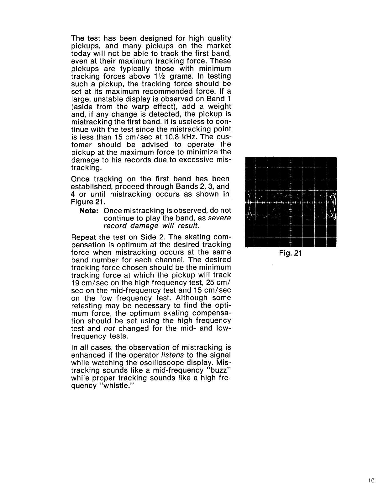
Once tracking on the first band has been
established, proceed through Bands
4
or until mistracking occurs as shown in
Figure 21.
Note:
Once mistracking is observed, do not
continue to play the band, as severe
record damage will result.
cm/sec at 10.8 kHz. The cus-
11/2 grams. In testing
1
mis-
2,3, and
Repeat the test on Side 2. The skating com-
pensation is optimum at the desired tracking
force when mistracking occurs at the same
band number for each channel. The desired
tracking force chosen should be the minimum
tracking force at which the pickup will track
19
cm/sec on the high frequency test, 25 cm/
sec on the mid-frequency test and 15 cmlsec
on the low frequency test. Although some
retesting may be necessary to find the optimum force, the optimum skating compensa-
tion should be set using the high frequency
test and not changed for the mid- and
frequency tests.
In all cases, the observation of mistracking is
enhanced if the operator listens to the signal
while watching the oscilloscope display. Mistracking sounds like a mid-frequency "buzz"
while proper tracking sounds like a high fre-
quency "whistle."
low-
Fig.
21
Page 12

Mid-Frequency Trackability Test
5,
6,
7,
&
8.
(BANDS
The display for the mid-frequency test is obtained by depressing the
on the test panel. The display will resemble
Figure 22, while the pickup is tracking.
tracking will change the display to resemble
Figure 23.
Low-Frequency Trackability Test
(BANDS 5,
With the
and pickup tracking, the display will resemble
Figure 24. Mistracking will change the display
to resemble Figure 25.
Note:
IX.
CHECKING
TTR-103 AND TTR-109
A log of usage of the TTR-103 and TTR109 should be maintained, since a record
should be used only for a limited period of
time. After about 25 tests, the record
should be checked
known trackability. The TTR-103 should
be compared to another copy of the
103. The TTR-109 is identical on both
sides, so one side should be compared
to the other. In either case, the cartridge
should exhibit the same tracking capabilities, and a similar pattern should be
observed on the oscilloscope for corresponding bands on the new and used
records. When a major difference is
noted, a new TTR-103 should be used, or
the TTR-109 should be turned to the new
side. When substituting a new TTR-103 or
using Side 2 of TTR-109, a new record
should be ordered, so that one new copy
will always be available.
6,
7,
"Low/Mid" button still depressed
The exact display for the low- and
mid-frequency tests will again depend on the particular pickup and
record. Also, in the presence of a
record warp, the operator must judge
when the pickup is mistracking a
band most of the time.
SlDE 1 LATERAL)
"Low/MidM button
&
8.
SlDE 2 LATERAL)
WEAR
OF
THE SHURE
bv using a cartridge of
Mis-
TTR-
22
Fig.
Fig. 23
Fig. 24
Fig. 25
Page 13

ADDENDA
I.
MODEL C/PEK-3/T
The Model C/PEK-3/T consists of a Model C/PEK-3 Stereo Cartridge Analyzer
and a 240 to 120
from a 216 to 264
Vac autotransformer which allows the Analyzer to be operated
Vac, 50-60 Hz, power source.
The autotransformer is supplied with a permanently attached three-conductor
ac power (mains) cord without a connector on the "mains" end. A suitable
connector must be installed by qualified service personnel. To attach a connector, connect the brown conductor of the power cord to the "live" terminal
of the connector, the blue conductor to the "neutral" terminal, and the
green-
yellow conductor to the "earth" terminal.
To operate the Analyzer, plug the
C/PEK-3 power cord into the power receptacle provided on the autotransformer. Connect the power cord from the
autotransformer to the 240
operate as it would if it were directly connected to a 120
120
Vac (80 watts
maximum
Vac (mains) power source. The C/PEK-3 will now
Vac power source and
load)
will be available at the switched power outlet
on the front of the unit.
II. GUARANTEE
This Shure product is guaranteed in normal use to be free from electrical and
mechanical defects for a period of one year from date of purchase. Please
retain proof of purchase date. This guarantee includes all parts and labor.
This guarantee is in lieu of any and all other guarantees or warranties,
express or implied, and there shall be no recovery for any consequential
or incidental damages.
Ill. SHIPPING INSTRUCTIONS
Carefully repack the unit and return it prepaid to:
Shu re Brothers Incorporated
Attention: Service Department
1501 West Shure Drive
Arlington Heights, Illinois 60004
If
outsidethe united States, return the unit to your dealer or Authorized Shure
Service Center for repair. The unit will be returned to you prepaid.
Page 14

222
HARTREY AVE.. EVANSTON. IL.
60204
U.S.A.
AREA CODE
TWX:
910-231-0048
3121866.2200
.
CABLE: SHUREMICRO
TELEX:
72-4381
-
1
IZOYAC
NOTES
:
I.
UL
UP*CllOllS
SHOWN.
ELECTROLmC
L.
ALL RLSISTORS
J
IYL
SWIKYES
"
APvEETd
A.C. VOLTAWLS
'KOlr'S lNPUT,
VOLT-ES
WIM
WWLm-
A.C
VOLTAGE RCADINGS
APP(YlR1412
AND
ME- ZERO
A-C PUDlNGS
MlGM
DCPRSSSED.
CO/Y)*I
IN
MFD
AND
SOY
OR
MORC
SHOWN
IN
OTHLWISE
OR
orF
POSITIMI.
me
SET
ICI~OLRIATLLI~
A.C VOLTAGES IAYKN
A.C
VWMETCR. TD
METER
MPLICIER
BUTTON
MUST
NU
CLOWWlSE.
VnLhL
UNLESS OTdCllWlSt
MLD
i
VOLTS.
~HLMU.
MX
LLCT
OR
RIOllT,
M
URCUIT,
BE
DEPRESED
ALL
MY
OTHER
Y*n
*IS%'
TEST 5UELTOI
WD
DC.
U4CtTm
WA~.
10%
IN
WlTH
INPUT SELECTOR
WITH
IOMR
P-ID
SLULCT-
CONTSOL
TAKEN
WITH
VOLTAOES
UNLESS
mr
OUT
4OOC.L
EDI
TSWUBILlTY
1MV.U.
WVM.
&RE
S~WN
D~%l."h~i~E~-.c5?$Z?~C->Zk'=.GE;L
TALW
WlW
TMU
WNLL
MODEL CIPEK
-
3
STEREO CARTRIDGE ANALYZER
CIRCUIT DIAGRAM
REPLACEMENT PARTS LIST
SHURE PART QTV. IN SHURE PART OTY. IN
ITEM NUMBER RKC KIT DESCRIPTION ITEM NUMBER RKC KIT DESCRIPTION
Dl. D2 RKCZl 4 Diode, Silicon. 100V. R6 46A036 1 Potentiometer, 50k
MCl, MCZ
PL1
0101, 0103,
0105,0107,
0109,0111
0102, 0104.
Q106. Q108,
0110,0112
86A803
RKC45
RKC89
86A348
1/2A (Motorola IN40021
1
Dual Operational Amplifier
(Motorola
or
Signetics N5558V)
1
Pilot Lamp (Leecraft
36N1311-6)
4
Transistor. Silicon, NPN
(Motorola
1
Transistor. Sllicon. PNP
(Motorola
MC1458C-P1
ZN5210)
2N5087)
TI 51AZ53 1 Transformer. Power
-
-
-
-
-
-
95A615
55A110
55A109
55Alll
RKC2
950552
1
Meter Assembly.
instruments 361, A-Scale)
Ac Switch. DPDT
1
(Alco 205N-49)
Push-Button Switch.
1
7-Station
Push-Button Switch, SPDT
1
(Switchcraft 953)
Ac Line Cord with Plug
1
(Eelden 17238)
Ac Receptacle
1
VU
(API
 Loading...