

Page 1
222 HARTREY AVE.. EVANSTON. IL. 60204 U.S.A.
DATA
MODEL
CB42
@
AREA
CODE 312/328-9000 . CABLE:
SHUREMICRO
SHEET
i
CONTROLLED MAGNETICa CITIZENS BAND MICROPHONE
GENERAL
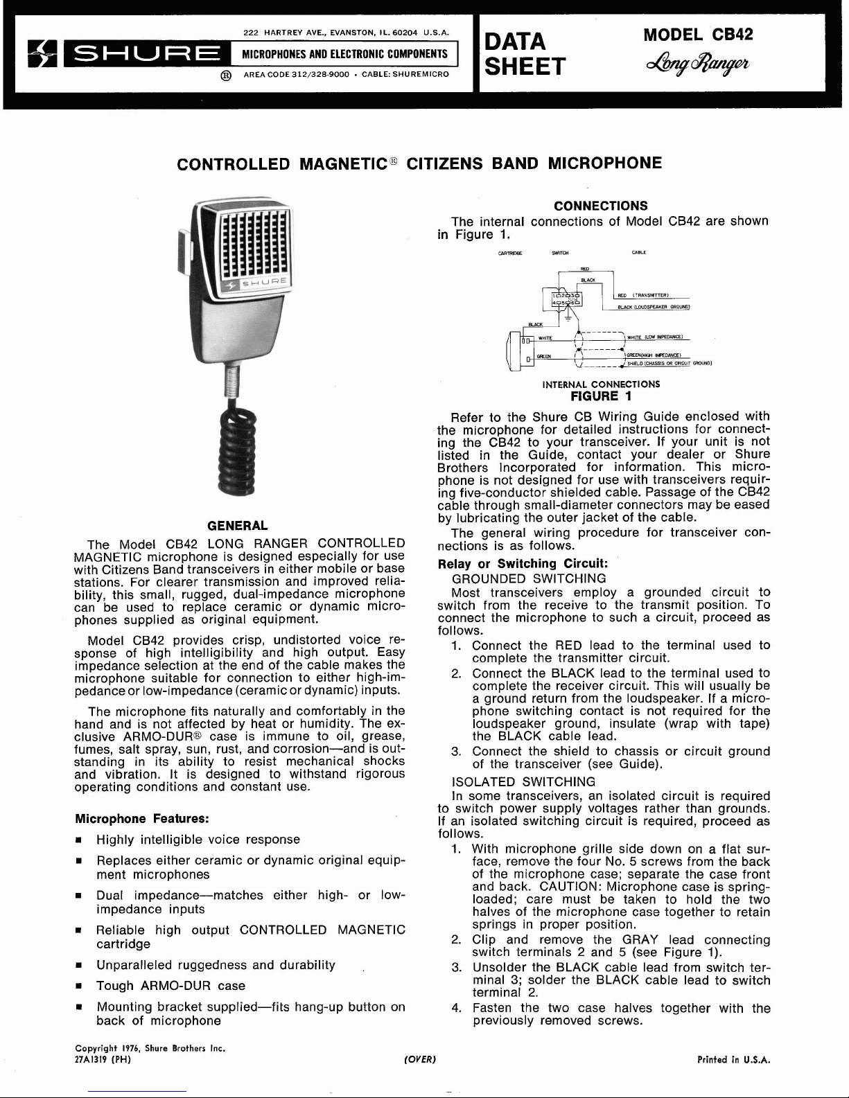
The Model CB42 LONG RANGER CONTROLLED
MAGNETIC microphone is designed especially for use
with Citizens Band transceivers in either mobile or base
stations. For clearer transmission and improved reliability, this small, rugged, dual-impedance microphone
can be used to replace ceramic or dynamic microphones supplied as original equipment.
Model CB42 provides crisp, undistorted voice re-
sponse of high intelligibility and high output. Easy
impedance selection at the end of the cable makes the
microphone suitable for connection to either
high-im-
pedance or low-impedance (ceramic or dynamic) inputs.
The microphone fits naturally and comfortably in the
hand and is not affected by heat or humidity. The exclusive
ARMO-DURD case is immune to oil, grease,
fumes, salt spray, sun, rust, and corrosion-and is outstanding in its ability to resist mechanical shocks
and vibration. It is designed to withstand rigorous
operating conditions and constant use.
Microphone Features:
Highly intelligible voice response
Replaces either ceramic or dynamic original equip-
ment microphones
Dual impedance-matches either high- or low-
impedance inputs
Reliable high output CONTROLLED MAGNETIC
cartridge
Unparalleled ruggedness and durability
Tough ARMO-DUR case
Mounting bracket supplied-fits hang-up button on
back of microphone
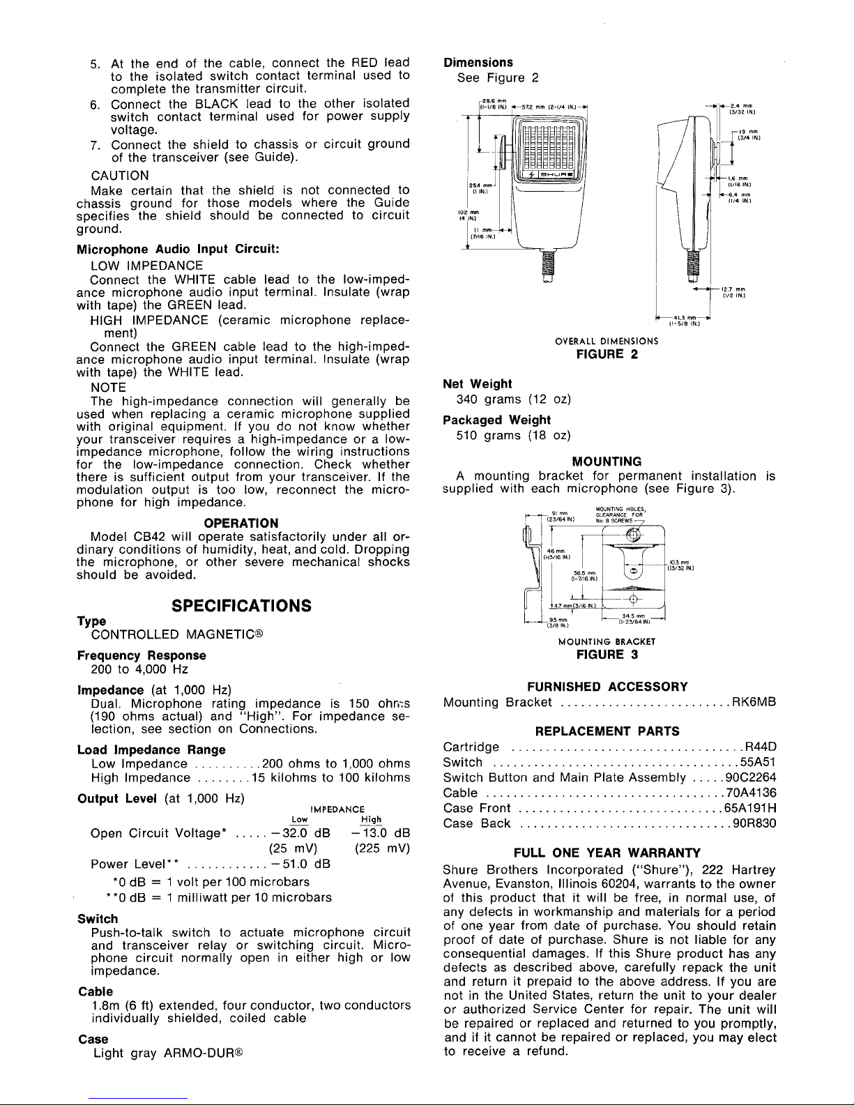
CONNECTIONS
The internal connections of Model CB42 are shown
in
Figure
1.
INTERNAL
CONNECTIONS
FIGURE
1
Refer to the Shure CB Wiring Guide enclosed with
the microphone for detailed instructions for connecting the CB42 to your transceiver. If your unit is not
listed in the Guide, contact your dealer or Shure
Brothers Incorporated for information. This microphone is not designed for use with transceivers requiring five-conductor shielded cable. Passage of the CB42
cable through small-diameter connectors may be eased
by lubricating the outer jacket of the cable.
The general wiring procedure for transceiver connections is as follows.
Relay or Switching Circuit:
GROUNDED SWITCHING
Most transceivers employ a grounded circuit to
switch from the receive to the transmit position. To
connect the microphone to such a circuit, proceed as
follows.
1.
Connect the RED lead to the terminal used to
complete the transmitter circuit.
2. Connect the BLACK lead to the terminal used to
complete the receiver circuit. This will usually be
a ground return from the loudspeaker. If a microphone switching contact is not required for the
loudspeaker ground, insulate (wrap with tape)
the BLACK cable lead.
3.
Connect the shield to chassis or circuit ground
of the transceiver (see Guide).
ISOLATED SWITCHING
In some transceivers, an isolated circuit is required
to switch power supply voltages rather than grounds.
If an isolated switching circuit is required, proceed as
follows.
1.
With microphone grille side down on a flat surface, remove the four No.
5
screws from the back
of the microphone case; separate the case front
and back. CAUTION: Microphone case is
spring-
loaded; care must be taken to hold the two
halves of the microphone case together to retain
springs in proper position.
2. Clip and remove the GRAY lead connecting
switch terminals 2 and
5
(see Figure
1).
3.
Unsolder the BLACK cable lead from switch terminal
3;
solder the BLACK cable lead to switch
terminal 2.
4. Fasten the two case halves together with the
previously removed screws.
Copyright
1976,
Shure Brothers Inc.
27A1319
(PH)
(OVER)
Printed in
U.S.A.
Page 2
5.
At the end of the cable, connect the RED lead
to the isolated switch contact terminal used to
complete the transmitter circuit.
6. Connect the BLACK lead to the other isolated
switch contact terminal used for power supply
voltage.
7.
Connect the shield to chassis or circuit ground
of the transceiver (see Guide).
CAUTION
Make certain that the shield is not connected to
chassis ground for those models where the Guide
specifies the shield should be connected to circuit
ground.
Microphone Audio Input Circuit:
LOW IMPEDANCE
Connect the WHITE cable lead to the
low-impedance microphone audio input terminal. Insulate (wrap
with tape) the GREEN lead.
HIGH IMPEDANCE (ceramic microphone replace-
ment)
Connect the GREEN cable lead to the
high-impedance microphone audio input terminal. Insulate (wrap
with tape) the WHITE lead.
NOTE
The high-impedance connection will generally be
used when replacing a ceramic microphone supplied
with original equipment. If you do not know whether
your transceiver requires a high-impedance or a
low-
impedance microphone, follow the wiring instructions
for the low-impedance connection. Check whether
there is sufficient output from your transceiver. If the
modulation output is too low, reconnect the micro-
phone for high impedance.
OPERATION
Model CB42 will operate satisfactorily under all or-
dinary conditions of humidity, heat, and cold. Dropping
the microphone, or other severe mechanical shocks
should be avoided.
SPECIFICATIONS
TY pe
CONTROLLED MAGNETIC@
Frequency Response
200 to 4,000 Hz
lmpedance
(at 1,000 Hz)
Dual. Microphone rating impedance is 150 ohms
(190 ohms actual) and
"High". For impedance se-
lection, see section on Connections.
Load lmpedance Range
Low Impedance
.........
,200 ohms to 1,000 ohms
High Impedance
.......
.15 kilohms to 100 kilohms
Output Level
(at 1,000 Hz)
IMPEDANCE
Low
High
Open Circuit Voltage*
.....
-32.0 dB
-13.0
dB
(25
mV) (225 mV)
Power Level
* *
............
-
51.0 dB
*O
dB = 1 volt per 100 microbars
**0 dB
=
1 milliwatt per 10 microbars
Switch
Push-to-talk switch to actuate microphone circuit
and transceiver relay or switching circuit. Microphone circuit normally open in either high or low
impedance.
Cable
1.8m
(6
ft) extended, four conductor, two conductors
individually
shielaed, coiled cable
Case
Light gray ARMO-DUR@
Dimensions
See Figure 2
OVERALL
DIMENSIONS
FIGURE
2
Net Weight
340 grams (12 oz)
Packaged Weight
510 grams (18 oz)
MOUNTING
A mounting bracket for permanent installation is
supplied with each microphone (see Figure 3).
MOUNTlNG HOLES,
y(2:)rr,N)
CLEARANCE
FOR
Na
8
SCREWS
MOUNTING
BRACKET
FIGURE
3
FURNISHED ACCESSORY
.........................
Mounting Bracket RK6MB
REPLACEMENT PARTS
..................................
Cartridge R44D
....................................
Switch 55A51
Switch Button and Main Plate Assembly
....
.90C2264
Cable
...................................
70A4136
Case Front
..............................
65A191H
Case Back
...............................
90R830
FULL ONE YEAR WARRANTY
Shure Brothers Incorporated ("Shure"), 222 Hartrey
Avenue, Evanston, Illinois 60204, warrants to the owner
of this product that it will be free, in normal use, of
any defects in workmanship and materials for a period
of one year from date of purchase. You should retain
proof of date of purchase. Shure is not liable for any
consequential damages. If this Shure product has any
defects as described above, carefully repack the unit
and return it prepaid to the above address. If you are
not in the United States, return the unit to your dealer
or authorized Service Center for repair. The unit will
be repaired or replaced and returned to you promptly,
and if it cannot be repaired or replaced, you may elect
to receive a refund.
 Loading...