

Page 1
BLX4R Wireless Receiver
Récepteur sans fil BLX4R
BLX4R Drahtlosempfänger
Receptor inalámbrico BLX4R
Radioricevitore BLX4R
Беспроводной приемник BLX4R
BLX4R draadloze ontvanger
©2013 Shure Incorporated
27A21196 (Rev. 3)
Printed in U.S.A.
Page 2

Page 3
IMPORTANT SAFETY INSTRUCTIONS
1. READ these instructions.
2. KEEP these instructions.
3. HEED all warnings.
4. FOLLOW all instructions.
5. DO NOT use this apparatus near water.
6. CLEAN ONLY with dry cloth.
7. DO NOT block any ventilation openings. Allow sufficient distances for adequate ventilation and install in accordance with the manufacturer’s instructions.
8. DO NOT install near any heat sources such as open flames, radiators, heat registers,
stoves, or other apparatus (including amplifiers) that produce heat. Do not place any open
flame sources on the product.
9. DO NOT defeat the safety purpose of the polarized or groundingtype plug. A polarized
plug has two blades with one wider than the other. A grounding type plug has two blades
and a third grounding prong. The wider blade or the third prong are provided for your
safety. If the provided plug does not fit into your outlet, consult an electrician for replacement of the obsolete outlet.
10. PROTECT the power cord from being walked on or pinched, particularly at plugs, convenience receptacles, and the point where they exit from the apparatus.
11. ONLY USE attachments/accessories specified by the manufacturer.
12. USE only with a cart, stand, tripod, bracket, or table specified by the manufacturer, or sold with the apparatus. When a cart is used, use caution when
moving the cart/apparatus combination to avoid injury from tip-over.
13. UNPLUG this apparatus during lightning storms or when unused for long
periods of time.
14. REFER all servicing to qualified service personnel. Servicing is required when the apparatus has been damaged in any way, such as power supply cord or plug is damaged,
liquid has been spilled or objects have fallen into the apparatus, the apparatus has been
exposed to rain or moisture, does not operate normally, or has been dropped.
15. DO NOT expose the apparatus to dripping and splashing. DO NOT put objects filled with
liquids, such as vases, on the apparatus.
16. The MAINS plug or an appliance coupler shall remain readily operable.
17. The airborne noise of the Apparatus does not exceed 70dB (A).
18. Apparatus with CLASS I construction shall be connected to a MAINS socket outlet with a
protective earthing connection.
19. To reduce the risk of fire or electric shock, do not expose this apparatus to rain or
moisture.
20. Do not attempt to modify this product. Doing so could result in personal injury and/or
product failure.
21. Operate this product within its specified operating temperature range.
This symbol indicates that dangerous voltage constituting a risk of
electric shock is present within this unit.
This symbol indicates that there are important operating and maintenance instructions in the literature accompanying this unit.
WARNING: This product contains a chemical known to the State of California to cause cancer and birth
defects or other reproductive harm.
CONSIGNES DE SÉCURITÉ IMPORTANTES
1. LIRE ces consignes.
2. CONSERVER ces consignes.
3. OBSERVER tous les avertissements.
4. SUIVRE toutes les consignes.
5. NE PAS utiliser cet appareil à proximité de l'eau.
6. NETTOYER UNIQUEMENT avec un chiffon sec.
7. NE PAS obstruer les ouvertures de ventilation. Laisser des distances suffisantes pour
permettre une ventilation adéquate et effectuer l'installation en respectant les instructions
du fabricant.
8. NE PAS installer à proximité d'une source de chaleur telle qu'une flamme nue, un
radiateur, une bouche de chaleur, un poêle ou d'autres appareils (dont les amplificateurs)
produisant de la chaleur. Ne placer aucune source à flamme nue sur le produit.
9. NE PAS détériorer la sécurité de la fiche polarisée ou de la fiche de terre. Une fiche
polarisée comporte deux lames dont l'une est plus large que l'autre. Une fiche de terre
comporte deux lames et une troisième broche de mise à la terre. La lame la plus large ou
la troisième broche assure la sécurité de l'utilisateur. Si la fiche fournie ne s'adapte pas à
la prise électrique, demander à un électricien de remplacer la prise hors normes.
10. PROTÉGER le cordon d'alimentation afin que personne ne marche dessus et que rien ne
le pince, en particulier au niveau des fiches, des prises de courant et du point de sortie
de l'appareil.
11. UTILISER UNIQUEMENT les accessoires spécifiés par le fabricant.
12. UTILISER uniquement avec un chariot, un pied, un trépied, un support ou
une table spécifié par le fabricant ou vendu avec l'appareil. Si un chariot
est utilisé, déplacer l'ensemble chariot-appareil avec précaution afin de ne
pas le renverser, ce qui pourrait entraîner des blessures.
WICHTIGE SICHERHEITSHINWEISE
1. Diese Hinweise LESEN.
2. Diese Hinweise AUFBEWAHREN.
3. Alle Warnungen BEACHTEN.
4. Alle Hinweise BEFOLGEN.
5. Dieses Gerät NICHT in Wassernähe VERWENDEN.
6. NUR mit einem sauberen Tuch REINIGEN.
7. KEINE Lüftungsöffnungen verdecken. Hinreichende Abstände für ausreichende Belüftung
vorsehen und gemäß den Anweisungen des Herstellers installieren.
8. NICHT in der Nähe von Wärmequellen wie zum Beispiel offenen Flammen, Heizkörpern,
Wärmespeichern, Öfen oder anderen Hitze erzeugenden Geräten (einschließlich
Verstärkern) installieren. Keine Quellen von offenen Flammen auf dem Produkt platzieren.
9. Die Schutzfunktion des Schukosteckers NICHT umgehen. Ein Schukostecker verfügt
über zwei Steckerzinken sowie Schutzleiter. Bei dieser Steckerausführung dienen die
Schutzleiter Ihrer Sicherheit. Wenn der mitgelieferte Stecker nicht in die Steckdose passt,
einen Elektriker mit dem Austauschen der veralteten Steckdose beauftragen.
10. VERHINDERN, dass das Netzkabel gequetscht oder darauf getreten wird, insbesondere
im Bereich der Stecker, Netzsteckdosen und an der Austrittsstelle vom Gerät.
11. NUR das vom Hersteller angegebene Zubehör und entsprechende Zusatzgeräte
verwenden.
12. NUR in Verbindung mit einem vom Hersteller angegebenen oder mit dem Gerät
verkauften Transportwagen, Stand, Stativ, Träger oder Tisch verwenden. Wenn ein
Transportwagen verwendet wird, beim Verschieben der Transportwagen/Geräte-Einheit
vorsichtig vorgehen, um Verletzungen durch Umkippen zu verhüten.
13. Bei Gewitter oder wenn das Gerät lange Zeit nicht benutzt wird, das Netzkabel
HERAUSZIEHEN.
13. DÉBRANCHER l'appareil pendant les orages ou quand il ne sera pas utilisé pendant
longtemps.
14. CONFIER toute réparation à du personnel qualifié. Des réparations sont nécessaires
si l'appareil est endommagé d'une façon quelconque, par exemple : cordon ou prise
d'alimentation endommagé, liquide renversé ou objet tombé à l'intérieur de l'appareil,
exposition de l'appareil à la pluie ou à l'humidité, appareil qui ne marche pas normalement ou que l'on a fait tomber.
15. NE PAS exposer cet appareil aux égouttures et aux éclaboussements. NE PAS poser
des objets contenant de l'eau, comme des vases, sur l'appareil.
16. La prise SECTEUR ou un coupleur d’appareil électrique doit rester facilement utilisable.
17. Le bruit aérien de l'appareil ne dépasse pas 70 dB (A).
18. L'appareil de construction de CLASSE I doit être raccordé à une prise SECTEUR dotée
d'une protection par mise à la terre.
19. Pour réduire les risques d'incendie ou de choc électrique, ne pas exposer cet appareil à
la pluie ou à l'humidité.
20. Ne pas essayer de modifier ce produit. Cela risque de causer des blessures et/ou la
défaillance du produit.
21. Utiliser ce produit dans sa plage de températures de fonctionnement spécifiée.
Ce symbole indique la présence d'une tension dangereuse dans
l'appareil constituant un risque de choc électrique.
Ce symbole indique que la documentation fournie avec l'appareil contient des instructions d'utilisation et d'entretien importantes.
14. ALLE Reparatur- und Wartungsarbeiten von qualifiziertem Kundendienstpersonal
durchführen lassen. Kundendienst ist erforderlich, wenn das Gerät auf irgendwelche
Weise beschädigt wurde, z. B. wenn das Netzkabel oder der Netzstecker beschädigt
wurden, wenn Flüssigkeiten in das Gerät verschüttet wurden oder Fremdkörper
hineinfielen, wenn das Gerät Regen oder Feuchtigkeit ausgesetzt war, nicht normal
funktioniert oder fallen gelassen wurde.
15. Dieses Gerät vor Tropf- und Spritzwasser SCHÜTZEN. KEINE mit Wasser gefüllten
Gegenstände wie zum Beispiel Vasen auf das Gerät STELLEN.
16. Der Netzstecker oder eine Gerätesteckverbindung muss leicht zu betätigen sein.
17. Der Luftschall des Geräts überschreitet 70 dB (A) nicht.
18. Das Gerät mit Bauweise der KLASSE I muss mit einem Schukostecker mit Schutzleiter in
eine Netzsteckdose mit Schutzleiter eingesteckt werden.
19. Dieses Gerät darf nicht Regen oder Feuchtigkeit ausgesetzt werden, um das Risiko von
Bränden oder Stromschlägen zu verringern.
20. Nicht versuchen, dieses Produkt zu modifizieren. Ansonsten könnte es zu Verletzungen
und/oder zum Produktausfall kommen.
21. Dieses Produkt muss innerhalb des vorgeschriebenen Temperaturbereichs betrieben
werden.
Dieses Symbol zeigt an, dass gefährliche Spannungswerte, die ein
Stromschlagrisiko darstellen, innerhalb dieses Geräts auftreten.
Dieses Symbol zeigt an, dass das diesem Gerät beiliegende Handbuch
wichtige Betriebs- und Wartungsanweisungen enthält.
INSTRUCCIONES IMPORTANTES DE SEGURIDAD
1. LEA estas instrucciones.
2. CONSERVE estas instrucciones.
3. PRESTE ATENCION a todas las advertencias.
4. SIGA todas las instrucciones.
5. NO utilice este aparato cerca del agua.
6. LIMPIE UNICAMENTE con un trapo seco.
7. NO obstruya ninguna de las aberturas de ventilación. Deje espacio suficiente para
proporcionar ventilación adecuada e instale los equipos según las instrucciones del
fabricante.
8. NO instale el aparato cerca de fuentes de calor tales como llamas descubiertas, radiadores, registros de calefacción, estufas u otros aparatos (incluyendo amplificadores) que
produzcan calor. No coloque artículos con llamas descubiertas en el producto.
9. NO anule la función de seguridad del enchufe polarizado o con clavija de puesta a tierra.
Un enchufe polarizado tiene dos patas, una más ancha que la otra. Un enchufe con puesta a tierra tiene dos patas y una tercera clavija con puesta a tierra. La pata más ancha
o la tercera clavija se proporciona para su seguridad. Si el tomacorriente no es del tipo
apropiado para el enchufe, consulte a un electricista para que sustituya el tomacorriente
de estilo anticuado.
10. PROTEJA el cable eléctrico para evitar que personas lo pisen o estrujen, particularmente
en sus enchufes, en los tomacorrientes y en el punto en el cual sale del aparato.
11. UTILICE únicamente los accesorios especificados por el fabricante.
12. UTILICE únicamente con un carro, pedestal, trípode, escuadra o mesa del
tipo especificado por el fabricante o vendido con el aparato. Si se usa un
carro, el mismo debe moverse con sumo cuidado para evitar que se vuelque
con el aparato.
13. DESENCHUFE el aparato durante las tormentas eléctricas, o si no va a ser utilizado por
un lapso prolongado.
14. TODA reparación debe ser llevada a cabo por técnicos calificados. El aparato requiere
reparación si ha sufrido cualquier tipo de daño, incluyendo los daños al cordón o enchufe
eléctrico, si se derrama líquido sobre el aparato o si caen objetos en su interior, si ha sido
expuesto a la lluvia o la humedad, si no funciona de modo normal, o si se ha caído.
15. NO exponga este aparato a chorros o salpicaduras de líquidos. NO coloque objetos
llenos con líquido, tales como floreros, sobre el aparato.
16. El enchufe de alimentación o un acoplador para otros aparatos deberá permanecer en
buenas condiciones de funcionamiento.
17. El nivel de ruido transmitido por el aire del aparato no excede de 70 dB(A).
18. Los aparatos de fabricación CLASE I deberán conectarse a un tomacorriente de ALIMENTACION con clavija de puesta a tierra protectora.
19. Para reducir el riesgo de causar un incendio o sacudidas eléctricas, no exponga este
aparato a la lluvia ni a humedad.
20. No intente modificar este producto. Hacerlo podría causar lesiones personales y/o la falla
del producto.
21. Utilice este producto únicamente dentro de la gama de temperaturas de funcionamiento
especificadas.
Este símbolo indica que la unidad contiene niveles de voltaje peligrosos
que representan un riesgo de choques eléctricos.
Este símbolo indica que la literatura que acompaña a esta unidad contiene instrucciones importantes de funcionamiento y mantenimiento.
Page 4
ISTRUZIONI IMPORTANTI PER LA SICUREZZA
1. LEGGETE queste istruzioni.
2. CONSERVATELE.
3. OSSERVATE tutte le avvertenze.
4. SEGUITE tutte le istruzioni.
5. NON usate questo apparecchio vicino all'acqua.
6. PULITE l'apparecchio SOLO con un panno asciutto.
7. NON ostruite alcuna apertura per l'aria di raffreddamento. Consentite distanze sufficienti
per un'adeguata ventilazione e installate l'apparecchio seguendo le istruzioni del costruttore.
8. NON installate l'apparecchio accanto a fonti di calore, quali fiamme libere, radiatori, aperture per l'efflusso di aria calda, forni o altri apparecchi (amplificatori inclusi) che generano
calore. Non esponete il prodotto a fonti di calore non controllate.
9. NON modificate la spina polarizzata o con spinotto di protezione per non alterarne
la funzione di sicurezza. Una spina polarizzata è dotata di due lame, una più ampia
dell'altra. Una spina con spinotto è dotata di due lame e di un terzo polo di messa a terra.
La lama più ampia ed il terzo polo hanno lo scopo di tutelare la vostra incolumità. Se la
spina in dotazione non si adatta alla presa di corrente, rivolgetevi ad un elettricista per far
eseguire le modifiche necessarie.
10. EVITATE di calpestare il cavo di alimentazione o di comprimerlo, specie in corrispondenza di spine, prese di corrente e punto di uscita dall'apparecchio.
11. USATE ESCLUSIVAMENTE i dispositivi di collegamento e gli accessori
specificati dal costruttore.
12. USATE l'apparecchio solo con carrelli, sostegni, treppiedi, staffe o tavoli
specificati dal produttore o venduti unitamente all'apparecchio stesso. Se usate un carrello, fate attenzione quando lo spostate con l'apparecchio collocato
su di esso, per evitare infortuni causati da un eventuale ribaltamento del carrello stesso.
13. Durante i temporali o in caso di inutilizzo prolungato dell'apparecchio, SCOLLEGATELO
dalla presa di corrente.
14. Per qualsiasi intervento, RIVOLGETEVI a personale di assistenza qualificato. È necessario intervenire sull'apparecchio ogniqualvolta è stato danneggiato, in qualsiasi modo;
ad esempio la spina o il cavo di alimentazione sono danneggiati, si è versato liquido
sull'apparecchio o sono caduti oggetti su di esso, l'apparecchio è stato esposto alla pioggia o all'umidità, non funziona normalmente o è caduto.
15. NON esponete l'apparecchio a sgocciolamenti o spruzzi. NON appoggiate
sull'apparecchio oggetti pieni di liquidi, ad esempio vasi da fiori.
16. La spina ELETTRICA o l'accoppiatore per elettrodomestici deve restare prontamente
utilizzabile.
17. Il rumore aereo dell'apparecchio non supera i 70 dB (A).
18. L'apparecchio appartenente alla CLASSE I deve essere collegato ad una presa elettrica
dotata di messa a terra di protezione.
19. Per ridurre il rischio di incendio o folgorazione, non esponete questo apparecchio alla
pioggia o all'umidità.
20. Non tentate di modificare il prodotto. Tale operazione può causare infortuni e/o il guasto
del prodotto stesso.
21. Utilizzate questo prodotto entro la gamma di temperatura operativa specificata.
Questo simbolo indica la presenza di alta tensione all'interno
dell'apparecchio, che comporta il rischio di folgorazione.
Questo simbolo indica la presenza di istruzioni importanti per l'uso e la
manutenzione nella documentazione in dotazione all'apparecchio.
ВАЖНЫЕ ИНСТРУКЦИИ ПО ТЕХНИКЕ БЕЗОПАСНОСТИ
1. ПРОЧИТАЙТЕ эти инструкции.
2. СОХРАНИТЕ эти инструкции.
3. ОБРАЩАЙТЕ ВНИМАНИЕ на все предупреждения.
4. СЛЕДУЙТЕ всем инструкциям.
5. НЕ пользуйтесь этим прибором вблизи воды.
6. ЧИСТИТЕ ТОЛЬКО сухой тканью.
7. НЕ закрывайте никакие вентиляционные отверстия. Оставляйте расстояния, нужные
для достаточной вентиляции, и выполняйте установку в соответствии с инструкциями
изготовителя.
8. НЕ устанавливайте вблизи каких бы то ни было источников тепла — открытого
пламени, радиаторов, обогревателей, печей или других приборов (включая усилители),
выделяющих тепло. Не помещайте на изделие источники открытого пламени.
9. НЕ пренебрегайте защитными свойствами поляризованной или заземляющей вилки.
Поляризованная вилка имеет два ножевых контакта, из которых один шире другого.
Заземляющая вилка имеет два ножевых контакта и третий, заземляющий, штырь.
Более широкий контакт или третий штырь предусматриваются для безопасности. Если
вилка прибора не подходит к вашей розетке, обратитесь к электрику для замены
розетки устаревшей конструкции.
10. ЗАЩИТИТЕ силовой шнур, чтобы на него не наступали и чтобы он не был пережат,
особенно в местах подсоединения к вилкам, розеткам и в месте выхода из прибора.
11. ИСПОЛЬЗУЙТЕ ТОЛЬКО те принадлежности и приспособления, которые
предусмотрены изготовителем.
12. ИСПОЛЬЗУЙТЕ только с тележкой, стендом, штативом, кронштейном или
столом, которые предусмотрены изготовителем или наглухо прикреплены к
прибору. При использовании тележки будьте осторожны, когда передвигаете
тележку вместе с прибором — переворачивание может привести к травме.
BELANGRIJKE VEILIGHEIDSINSTRUCTIES
1. LEES deze instructies.
2. BEWAAR deze instructies.
3. NEEM alle waarschuwingen in acht.
4. VOLG alle instructies op.
5. GEBRUIK dit apparaat NIET in de buurt van water.
6. REINIG UITSLUITEND met een droge doek.
7. DICHT GEEN ventilatieopeningen AF. Zorg dat er voldoende afstand wordt gehouden
voor adequate ventilatie. Installeer het product volgens de instructies van de fabrikant.
8. Plaats het apparaat NIET in de buurt van warmtebronnen, zoals vuur, radiatoren,
warmteroosters, kachels of andere apparaten (waaronder versterkers) die warmte
genereren. Plaats geen vuurbronnen in de buurt van het product.
9. Zorg ervoor dat de beveiliging van de gepolariseerde stekker of randaardestekker
INTACT blijft. Een gepolariseerde stekker heeft twee pennen waarbij er één breder is
dan de andere. Een randaardestekker heeft twee pennen en een extra aardaansluiting.
De breedste pen en de aardaansluiting zijn bedoeld om uw veiligheid te garanderen. Als
de meegeleverde stekker niet in de contactdoos past, vraag een elektricien dan om de
verouderde contactdoos te vervangen.
10. BESCHERM het netsnoer tegen erop lopen of afknelling, vooral in de buurt van stekkers
en uitgangen en op de plaats waar deze het apparaat verlaten.
11. GEBRUIK UITSLUITEND door de fabrikant gespecificeerde hulpstukken/accessoires.
12. GEBRUIK het apparaat UITSLUITEND in combinatie met een door de
fabrikant gespecificeerde wagen, standaard, driepoot, beugel of tafel of
met een meegeleverde ondersteuning. Wees bij gebruik van een wagen
voorzichtig tijdens verplaatsingen van de wagen/apparaat-combinatie om
letsel door omkantelen te voorkomen.
13. ОТСОЕДИНЯЙТЕ прибор ОТ СЕТИ во время грозы или если он не используется
длительное время.
14. ПОРУЧИТЕ все обслуживание квалифицированному техническому персоналу.
Обслуживание требуется при каком-либо повреждении прибора, например, при
повреждении шнура питания или вилки, если на прибор была пролита жидкость или
на него упал какой-либо предмет, если прибор подвергся воздействию дождя или
сырости, не функционирует нормально или если он падал.
15. НЕ допускайте попадания на прибор капель или брызг. НЕ ставьте на прибор сосуды
с жидкостью, например, вазы.
16. Вилка электропитания или штепсель прибора должны быть легко доступны.
17. Уровень воздушного шума этого аппарата не превышает 70 дБ (A).
18. Аппараты конструкции КЛАССА I необходимо подсоединять к СЕТЕВОЙ розетке с
защитным соединением для заземления.
19. Чтобы уменьшить риск возгорания или поражения электрическим током, не
допускайте попадания на этот аппарат дождя или влаги.
20. Не пытайтесь вносить изменения в это изделие. Это может привести к травме и (или)
выходу изделия из строя.
21. Эксплуатируйте это изделие в указанном диапазоне рабочих температур.
Этот знак показывает, что внутри прибора имеется опасное
напряжение, создающее риск электрического удара.
Этот знак показывает, что в сопроводительной документации
к прибору есть важные указания по его эксплуатации и
обслуживанию.
13. HAAL de stekker van dit apparaat uit de contactdoos tijdens onweer/bliksem of wanneer
het lange tijd niet wordt gebruikt.
14. Laat onderhoud altijd UITVOEREN door bevoegd servicepersoneel. Onderhoud moet
worden uitgevoerd wanneer het apparaat op enigerlei wijze is beschadigd, bijvoorbeeld
beschadiging van netsnoer of stekker, vloeistof of voorwerpen in het apparaat zijn
terechtgekomen, het apparaat is blootgesteld aan regen of vocht, niet naar behoren werkt
of is gevallen.
15. STEL het apparaat NIET bloot aan druppelend en rondspattend vocht. PLAATS GEEN
voorwerpen gevuld met vloeistof, bijvoorbeeld een vaas, op het apparaat.
16. De NETSTEKKER of een koppelstuk van het apparaat moet klaar voor gebruik zijn.
17. Het door het apparaat verspreide geluid mag niet meer zijn dan 70 dB(A).
18. Apparaten van een KLASSE I-constructie moeten worden aangesloten op een
WANDCONTACTDOOS met beschermende aardaansluiting.
19. Stel dit apparaat niet bloot aan regen of vocht om het risico op brand of elektrische
schokken te verminderen.
20. Probeer dit product niet te wijzigen. Anders kan lichamelijk letsel optreden en/of het
product defect raken.
21. Gebruik dit product binnen de gespecificeerde bedrijfstemperaturen.
Dit symbool geeft aan dat in deze eenheid een gevaarlijk spanning aanwezig is met het risico op een elektrische schok.
Dit symbool geeft aan dat in de documentatie bij deze eenheid belangrijke bedienings- en onderhoudsinstructies zijn opgenomen.
4
Page 5
Quick Start Guide
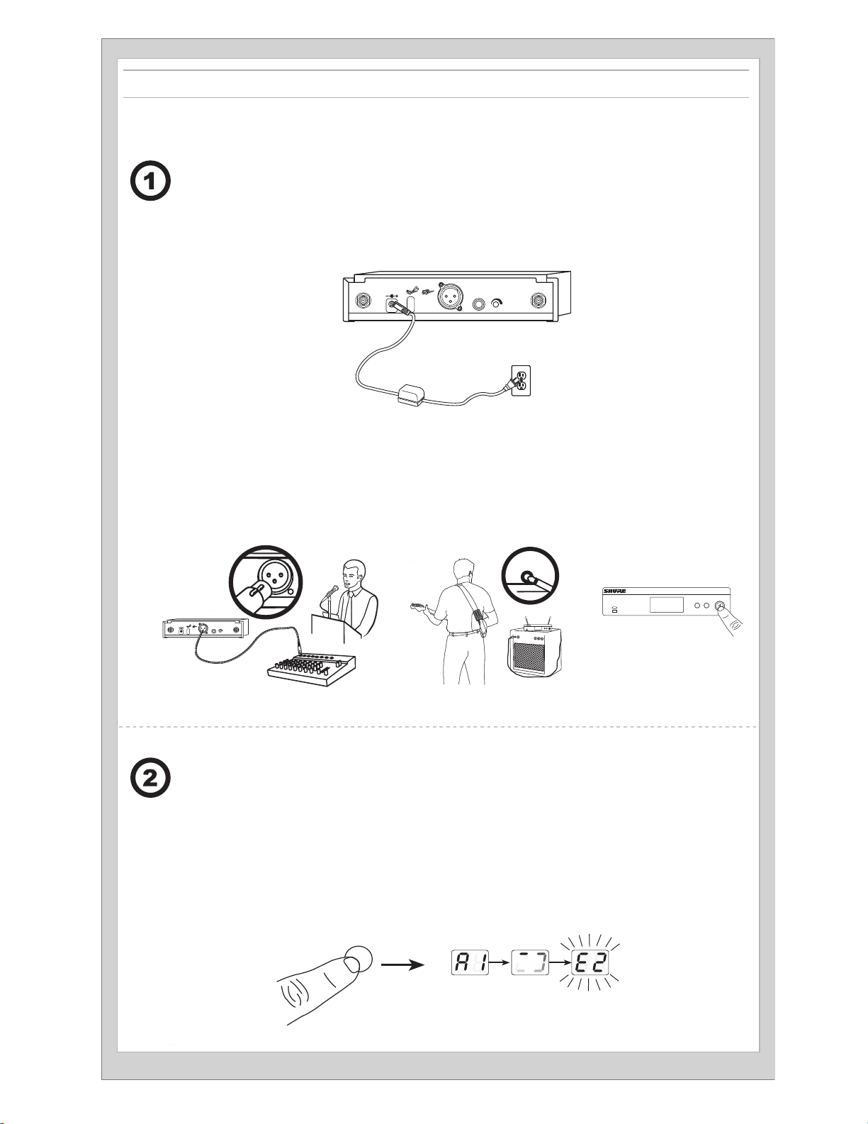
Connect receiver to power source.
Brancher le récepteur à une source d'alimentation.
Den Empfänger an die Stromversorgung
a)
anschließen.
Conecte el receptor a la fuente de alimentación.
Connect receiver to mixer or amplifier. Press
the power button to turn on the receiver.
Brancher le récepteur à un mélangeur ou un amplificateur. Appuyer sur le bouton d'alimentation
b)
pour allumer le récepteur.
Den Empfänger an das Mischpult oder den
Verstärker anschließen. Die Taste power drücken,
um den Empfänger einzuschalten.
Collegate il ricevitore alla presa di alimentazione.
Подключите приемник к источнику питания.
Sluit ontvanger aan op voedingsbron.
① ②
POWER
ANTENNA B
MIC OUT INSTRUMENT OUT VOLUME ANTENNA A
Conecte el receptor a la mezcladora o amplificador. Oprima el botón
de alimentación para encender el receptor.
Collegate il ricevitore al mixer o all'amplificatore. Premete il
pulsante power per accendere il ricevitore.
Подключите приемник к микшеру или усилителю. Чтобы
включить приемник, нажмите кнопку Power.
Sluit ontvanger aan op mengpaneel of versterker. Druk op
de aan/uit-knop om de ontvanger in te schakelen.
① ②
POWER
ANTENNA B
MIC OUT INSTRUMENT OUT VOLUME ANTENNA A
Press group button on receiver to perform
a group scan.
Appuyer sur le bouton group du récepteur pour effectuer un balayage des groupes.
Am Empfänger die group-Taste drücken, um
einen Gruppensuchlauf durchzuführen.
Oprima el botón de grupo en el receptor para
realizar un escaneo de grupo.
group
(A-Y)
BLX4R
BLX4R
group channel
(A-Y) (0-9)
group channel
(A-Y) (0-9)
Premete il pulsante group sul ricevitore per eseguire una ricerca del gruppo.
Чтобы выполнить сканирование групп,
нажмите на приемнике кнопку Group.
Druk op de knop 'group' op de ontvanger om een
groepsscan uit te voeren.
5
Page 6
Install batteries and turn on transmitter.
a)
Installer les piles et allumer l’émetteur.
Die Batterien/Akkus einlegen und den
Sender einschalten.
Instale las baterías y encienda el transmisor.
group
channel
(A-Y)
(0-9)
Installate le pile ed accendete il trasmettitore.
Вставьте батарейки и включите передатчик.
Plaats de batterijen en schakel de zender in.
On the transmitter, set the group and channel to
b)
match the receiver. The RF bars and battery LED
on the receiver should illuminate.
Sur l'émetteur, régler le groupe et le canal afin qu'ils correspondent à ceux du récepteur. Les barres RF et la LED des
piles du récepteur doivent s'allumer.
Am Sender Gruppe und Kanal entsprechend
der Empfängereinstellung einstellen. Auf dem
Empfänger sollten die HF-Balken und Akku-LEDs
aufleuchten.
En el transmisor, seleccione el grupo y canal para
que coincidan con el receptor. Se deben iluminar las
barras de RF y el LED de batería en el receptor.
Sul trasmettitore impostate il gruppo ed il canale corrispondenti a quelli del ricevitore. Le barre RF ed il LED della pila
situati sul ricevitore devono illuminarsi.
Установите на передатчике группу и канал
для согласования с настройкой приемника.
На приемнике должны загореться индикаторы
интенсивности РЧ сигнала и светодиод батарейки.
Stel de groep en het kanaal op de zender in zodat
deze overeenkomen met de ontvanger. De RF-balkjes
en batterij-LED op de ontvanger lichten op.
group channel
group
group
group
group
channel
channel
channel
6
Page 7
group
(A-Y)
channel
(0-9)
If setting up additional systems, leave the first transmitter and receiver on. For each additional receiver, manually set the group to match the
first receiver. Note: The receiver will automatically perform a channel scan to find an available frequency after the group has been selected. Set
the transmitter frequency to match the receiver.
Si l'on configure d'autres systèmes, laisser les premiers émetteur et récepteur allumés. Pour chaque système supplémentaire, régler manuellement le groupe pour qu'il corresponde à celui du premier récepteur. Remarque : une fois le groupe sélectionné, le récepteur exécutera automatiquement un scan des canaux afin de trouver une fréquence disponible. Régler la fréquence de l'émetteur pour qu'elle corresponde à celle du
récepteur.
Falls weitere Systeme eingerichtet werden, den ersten Sender und Empfänger eingeschaltet lassen. Für jeden weiteren Empfänger die Gruppe
manuell auf den ersten Empfänger einstellen. Hinweis: Der Empfänger führt automatisch einen Kanalscan durch, um nach der Auswahl der
Gruppe eine verfügbare Frequenz zu finden. Die Senderfrequenz entsprechend der des Empfängers einstellen.
Si está configurando sistemas adicionales, deje encendidos el primer transmisor y receptor. Por cada receptor adicional, fije manualmente el
grupo para hacerlo coincidir con el primer receptor. Nota: El receptor automáticamente realizará un escaneo de canales para encontrar una
frecuencia disponible después que se ha seleccionado el grupo. Fije la frecuencia del transmisor para que coincida con el receptor.
Se impostate altri sistemi, lasciate accesi il primo trasmettitore e ricevitore. Per ciascun ricevitore aggiuntivo, impostate manualmente il gruppo
in modo che corrisponda al quello del primo ricevitore. Nota: all'avvenuta selezione del gruppo il ricevitore esegue automaticamente una
scansione del canale per individuare una frequenza disponibile. Impostate la frequenza del trasmettitore in modo che corrisponda a quella del
ricevitore.
Пр настройке дополнительных систем оставьте включенными первый передатчик и приемник. Для каждого дополнительного
приемника вручную установите группу, соответствующую первому приемнику. Примечание. После выбора группы приемник
автоматически выполнит сканирование каналов и найдет свободную частоту. Согласуйте частоты передатчика и приемника.
Bij het instellen van aanvullende systemen laat u de eerste zender en ontvanger AAN staan. Stel handmatig voor elke aanvullende ontvanger
de groep zo in dat deze overeenkomt met de eerste ontvanger. Opmerking: Wanneer de groep is geselecteerd, voert de ontvanger automatisch
een kanaalscan uit om een beschikbare frequentie te zoeken. Stel de zenderfrequentie zo in dat deze overeenkomt met de ontvanger.
If sound is too faint or distorted, adjust the
gain accordingly.
Si le son est trop faible ou distordu, régler le gain en
conséquence.
Falls der Ton zu schwach oder verzerrt ist, die Verstärkung
dementsprechend korrigieren.
Si el sonido es demasiado débil o distorsionado,
ajuste la ganancia según sea necesario.
Se il suono è troppo debole o distorto, regolate il
guadagno di conseguenza.
Если звук слишком слабый или искажен,
подрегулируйте усиление.
Als het geluid te zacht of vervormd is, regel dan
de versterkingsfactor hierop af.
group
-10 dB
channel
-10 dB
group
channel
5 s
7
Page 8
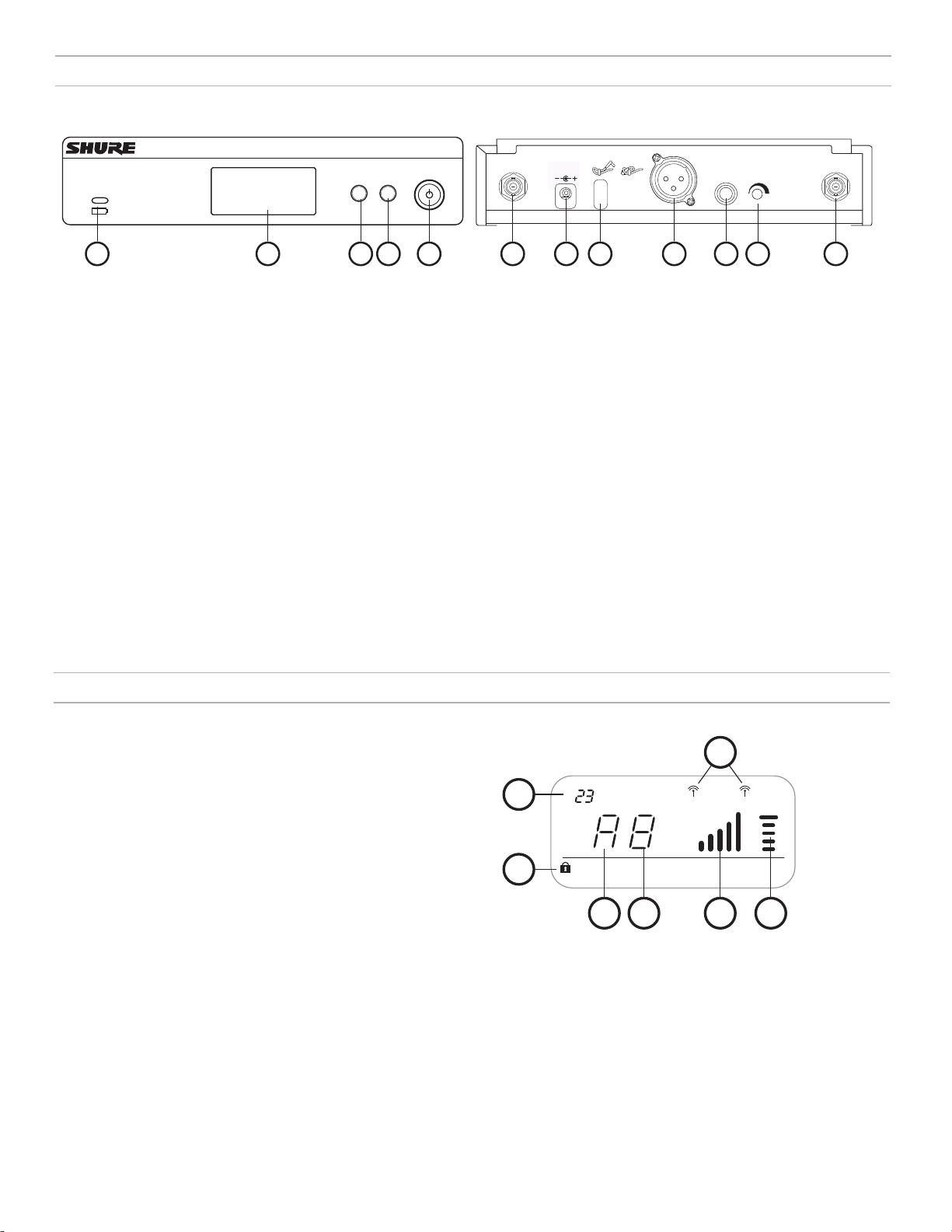
BLX4R Receiver
Front Panel
BLX4R
① Transmitter Battery LED
• Green = Runtime greater than 1 hour
• Red = Runtime less than 1 hour
② LCD Display
Displays receiver and transmitter
settings.
③ group Button
• Scan: push and release group button to scan for an open group and
channel
• Manual: push and hold group button
to select a group.
Rear Panel
group channel
(A-Y) (0-9)
ANTENNA B
21
3
④ channel Button
• Scan: push and release channel button to
scan for an open channel
• Manual: push and hold channel button to select a channel.
⑤ Power Button
Powers the receiver on/off.
⑥ Antenna Jack B
BNC connector for antenna B.
⑦ DC Power Jack
For DC external power supply (12 to 15 V DC).
4
5 6
POWER
MIC OUT INSTRUMENT OUT VOLUME ANTENNA A
7
98
⑧ Strain-relief loop for power cord
Secures power cord to receiver.
⑨ Mic Out XLR audio output jack
Supplies microphone-level audio output.
⑩ INST Out audio output jack
Supplies instrument-level audio signal.
⑪ Volume Control
Use a screwdriver to adjust the output
level.
⑫ Antenna Jack A
BNC connector for antenna A.
1110
12
Receiver LCD Screen
① TV Channel
TV channel for selected frequency.
② Receiver Lock
Indicates control and power lock enabled.
③ Group
Displays selected group.
④ Channel
Displays selected channel.
⑤ RF Signal Strength
Number of bars corresponds to RF signal strength. OL indicates
signal overload.
⑥ Audio Meter
Number of bars indicates audio signal level. OL indicates signal
clipping.
⑦ Active Antenna Indicator
Indicates active antenna for the diversity signal.
7
1
2
tv
group channel rf
3
4
AOLB
OL
audio
5 6
8
Page 9
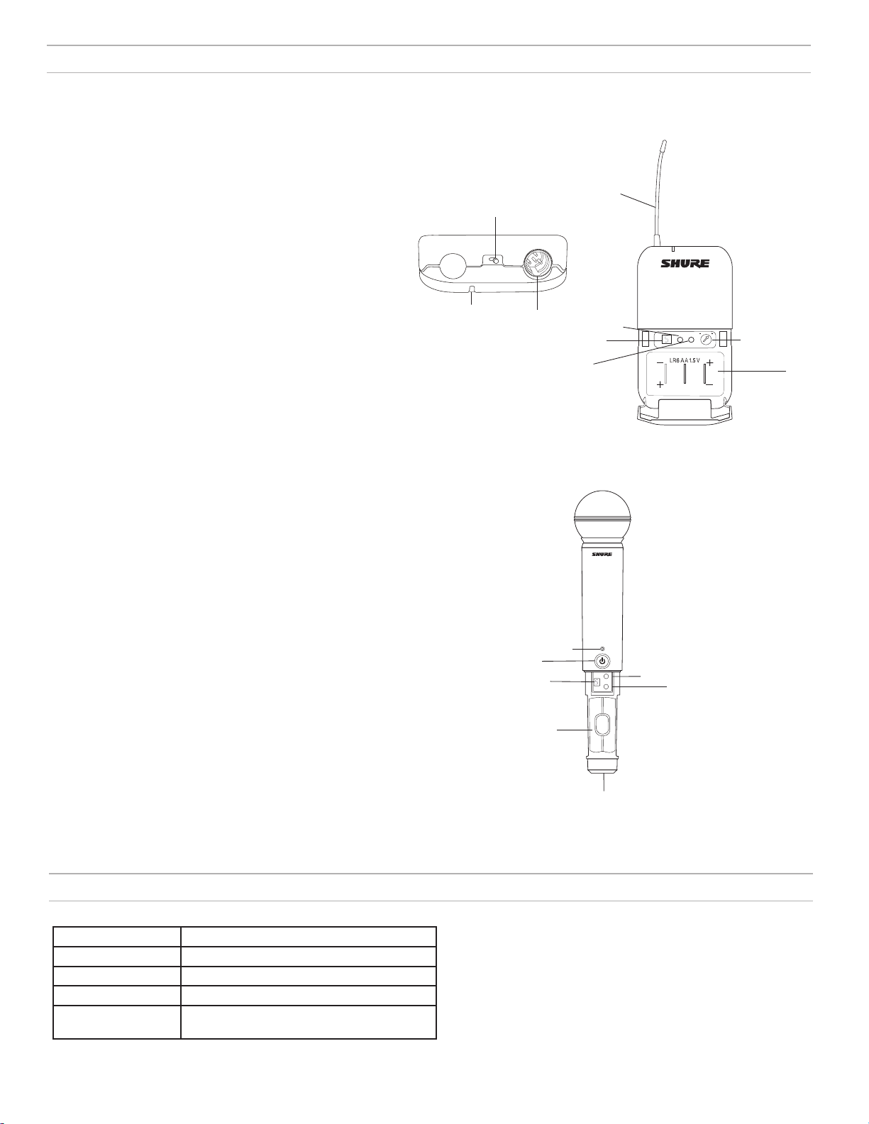
Transmitters
BLX1
① LED Indicator
Displays power and battery status (see table).
② power Switch
Toggles power on or off.
③ 4-Pin Microphone Input Jack (TA4 connector)
④ Antenna
⑤ group Button
Changes group setting.
⑥ LED Display
Displays group and channel setting.
⑦ channel Button
Changes channel setting.
⑧ Battery Compartment
⑨ Audio Gain Adjustment
Rotate to increase or decrease transmitter gain.
BLX2
① LED Indicator
Displays power and battery status (see table).
② power Button
Push to turn power on or off.
③ group Button
Changes group setting.
④ channel Button
Changes channel and gain setting.
⑤ LED Display
Displays group and channel setting.
⑥ Identification Cap
⑦ Battery Compartment
BLX1
BLX2
①
②
③
②
⑤
⑦
①
⑦
⑥
-10 dB
④
⑤
group
channel
③
④
group
channel
(A-Y)
(0-9)
⑨
⑧
Transmitter LED Indicators
LED Indicator Status
Green Ready
Rapidly Flashing Red Controls locked
Solid Red Battery power low (less than 1 hour remaining*)
Flashing Red and shuts
off
*For alkaline batteries only. For rechargeable batteries, solid red means the batteries are dead.
Batteries dead (change batteries to power on
transmitter)
⑥
9
Page 10
Single System Set Up
group
(A-Y)
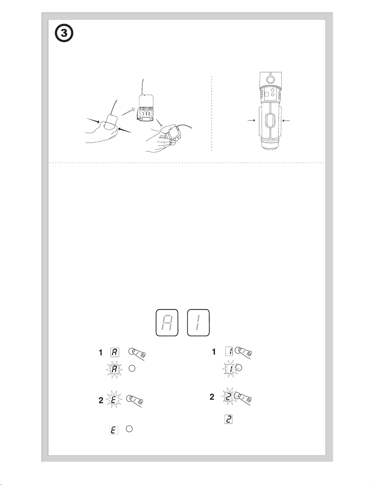
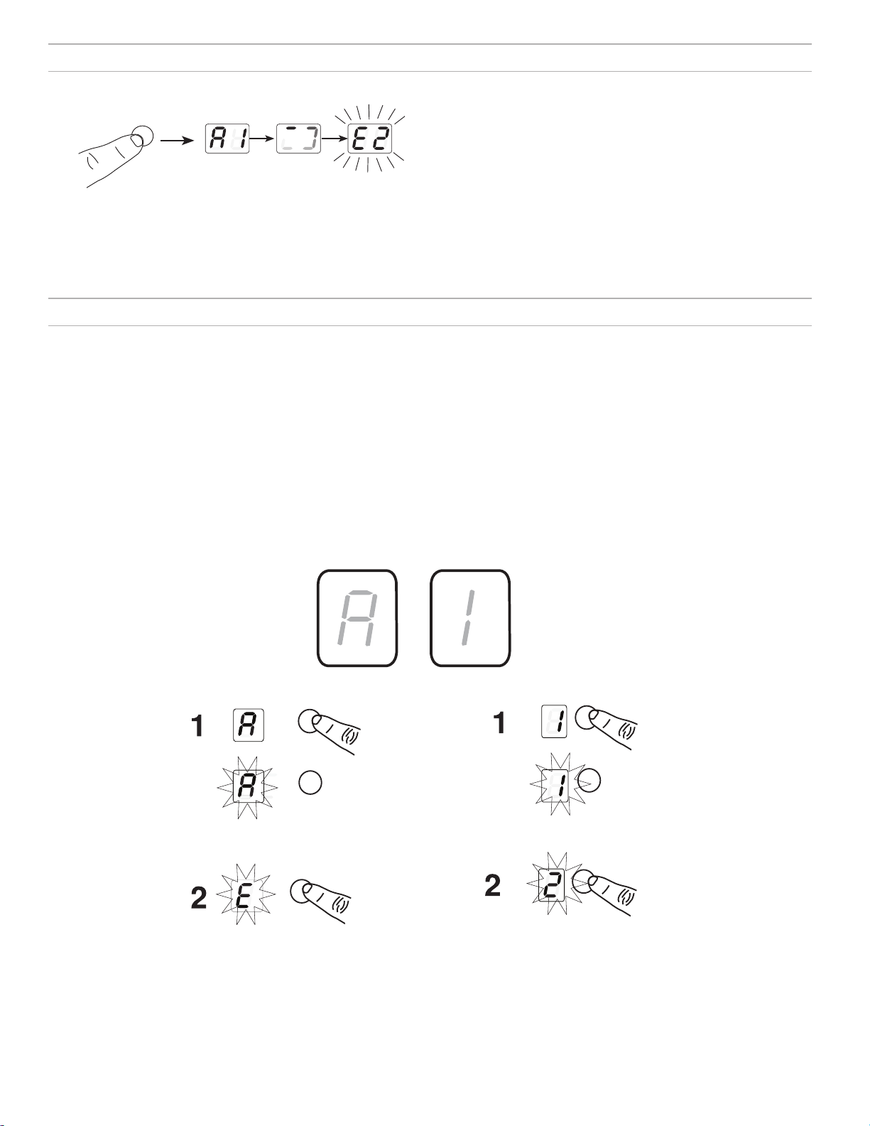
Setting Transmitter Group and Channel
Transmitter group and channel must be manually set to match the receiver.
Group (letter)
1. Press and release the group button on the transmitter to activate the display. Press the group button again and the display
flashes.
2. While the display is flashing, press the group button again to advance to the desired group setting.
Before you begin, turn off all transmitters and turn on any equipment (other
microphones or personal monitoring systems) that could cause interference
during the performance.
1. Press and release the group button on the receiver.
The receiver scans for the clearest group and channel.
Note: If you want to stop the scan, push the group button again.
2. Turn on transmitter and change the group and channel to match the receiver (See Setting Transmitter Group and Channel).
Once the system is set up, perform an audio check and adjust the gain if necessary.
Channel (number)
If channel needs to be changed, follow the same procedure using the channel
button instead of the group button.
Note:
• When the group and channel correctly match the receiver, the RF bars
and battery LED on the receiver illuminate.
• After manual setup, the transmitter alternately displays the group and
channel setting for about two seconds.
group
group
group
group channel
channel
channel
channel
10
Page 11

Multiple System Set Up
Up to 12 systems can operate simultaneously (band and RF environment dependent).
Important: Set up each system one-at-a-time. Once a receiver and transmitter are tuned to the same group and channel, leave the transmitter powered
on. Otherwise, scans from the other receivers will not detect that channel as occupied.
Turn on any other equipment that could cause interference during the performance so it will be detected during the group and channel scans in the following steps.
Before you begin system set up, turn all receivers
For the first receiver:
1. Perform a group scan to find the group with the most clear channels.
2. Turn on the first transmitter and change the group and channel to match the receiver.
3. Leave the transmitter on and continue with the additional systems.
Note: If the selected group does not contain enough open channels, manually select group "d" when setting up larger systems.
For each additional receiver:
1. Manually change the receiver to match the group setting of the first receiver. Recall that each time the group setting is changed, a channel scan is
automatically done.
2. Turn on the transmitter and change the group and channel to match the receiver.
3. Leave the transmitter on and continue to the next system.
4. Once all receivers are set up, perform an audio check on all microphones.
ON and all transmitters OFF.
Manually Setting Receiver Group and Channel
The receiver group may need to be changed as part of a multiple system setup.
Group (letter)
1. Hold the group button on the receiver until the display begins to flash.
2. While the display is flashing, press the group button again to advance to the next group.
Note: Only the group setting will be displayed during the manual setup.
3. Once the desired group is reached, release the group button. The receiver automatically performs a channel scan.
Channel (number)
Always use a channel selected by the channel scan. However, if necessary, the channel can be set manually. Follow the same steps above using the
channel button instead of the group button.
11
Page 12
group
(A-Y)
channel
(0-9)
13 mm
(.5 in.)
Tips to Improve Wireless System Performance
If you encounter interference or dropouts, try the following suggestions:
• Choose a different receiver channel
• Reposition the receiver so there is nothing obstructing a line of
sight to the transmitter (including the audience)
• Avoid placing transmitter and receiver where metal or other
dense materials may be present
• Move the receiver to the top of the equipment rack
• Remove nearby sources of wireless interference, such as cell phones,
two-way radios, computers, media players, Wi-Fi devices, and digital
signal processors
• Charge or replace the transmitter battery
• Keep transmitters more than two meters (6 feet) apart
• Keep the transmitter and receiver more than 5 meters (16 feet) apart
• During sound check, mark trouble spots and ask presenters or
performers to avoid those areas
Getting Good Sound
Correct Microphone Placement
• Hold the microphone within 12 inches from the sound source. For a warmer sound with
increased bass presence, move the microphone closer.
• Do not cover grille with hand.
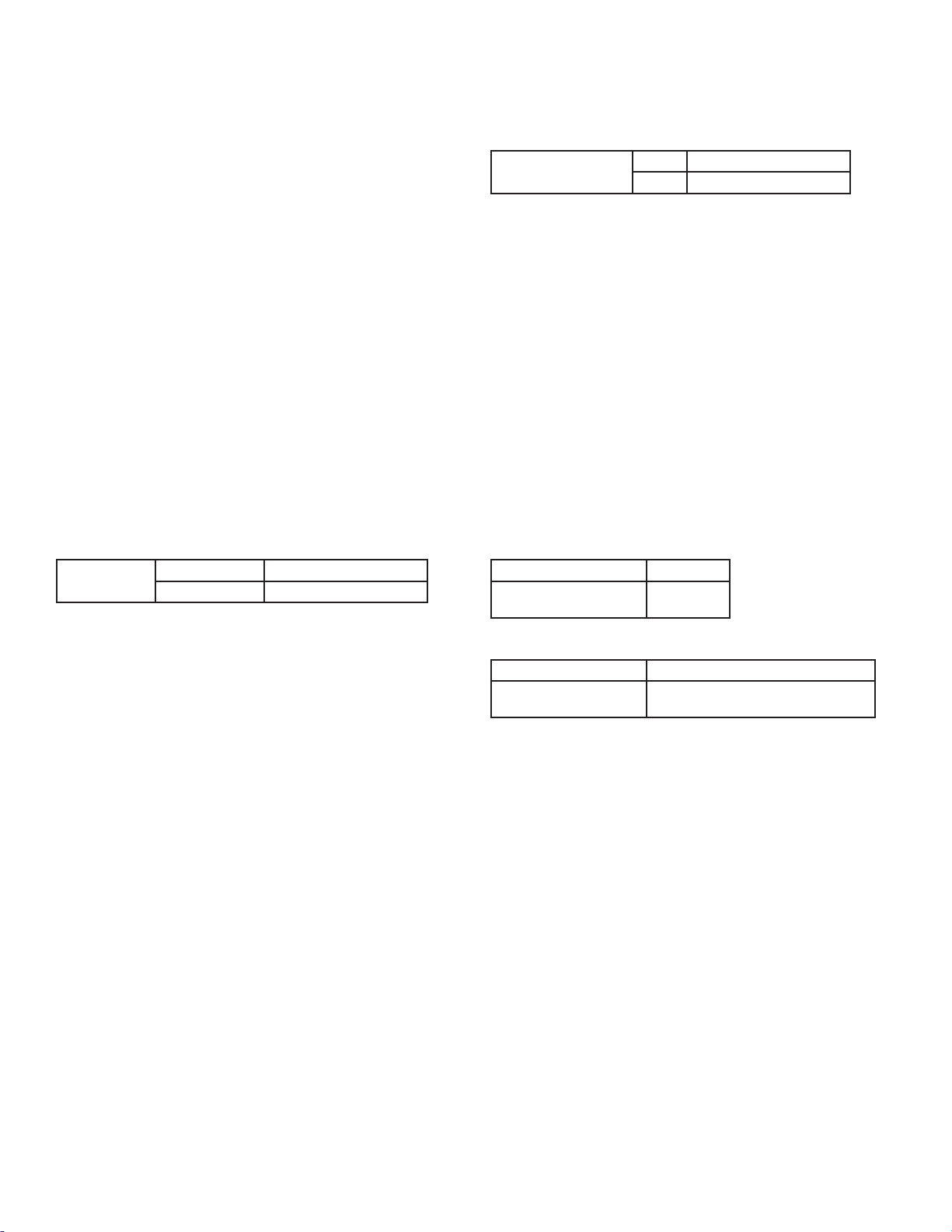
Wearing the Headworn Microphone
• Position the headworn microphone 13 mm (1/2 in.) from the corner of your mouth.
• Position lavalier and headworn microphones so that clothing, jewelry, or other items do not
bump or rub against the microphone.
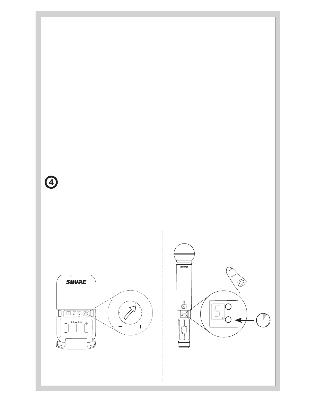
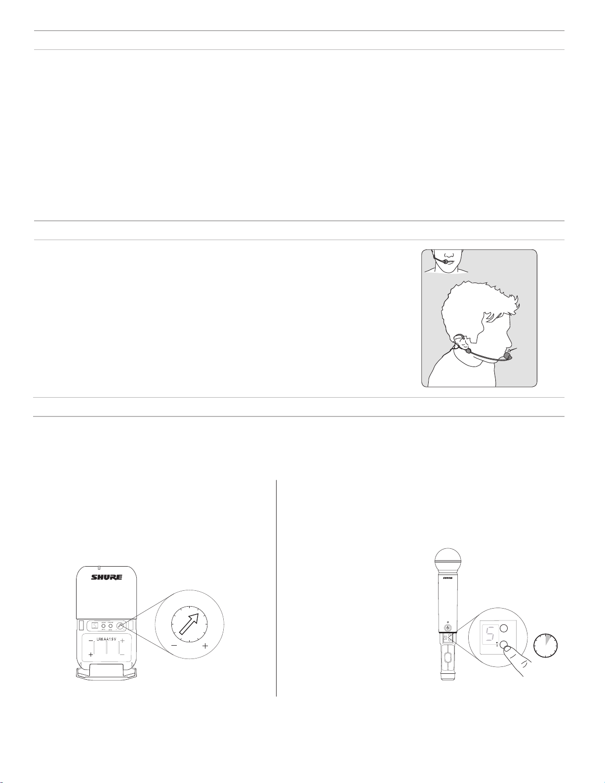
Adjusting Gain
Monitor the audio meter on the receiver display when setting the transmitter gain. The OL indicator should only illuminate infrequently when you speak
loudly or play your instrument loudly.
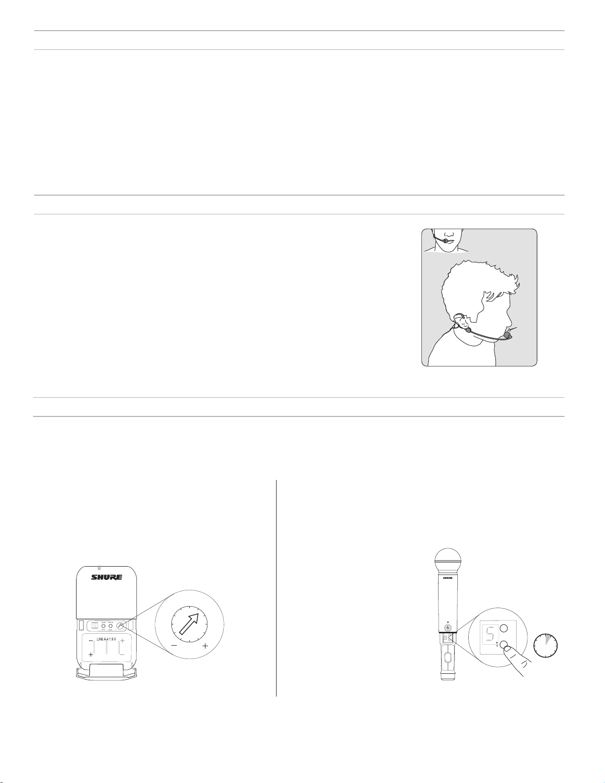
BLX1
Rotate the audio gain adjustment to increase (+) or decrease
(−) the gain until desired level is reached.
For instruments, turn gain to minimum setting. For lavaliers,
increase the gain as desired.
BLX2
The BLX2 features two gain level settings:
•
Default
• -10 dB
Use the default setting for most
situations. If the receiver audio OL
indicator displays often, set the microphone to -10 dB.
1. To change the gain to -10 dB,
hold down the channel button
until a small dot appears in the
lower right hand corner of the
transmitter display.
2. To change the gain back to default, hold the channel button
until the dot disappears.
-10 dB
group
5 s
channel
group
-10 dB
channel
12
Page 13
Batteries
Expected life for AA batteries is up to 14 hours (total battery life varies depending upon battery
type and manufacturer).
When the LED indicator turns red, it signifies "low battery" with approximately 60 minutes of remaining battery life.
For alkaline batteries only. For rechargeable batteries, solid red means the batteries are dead.
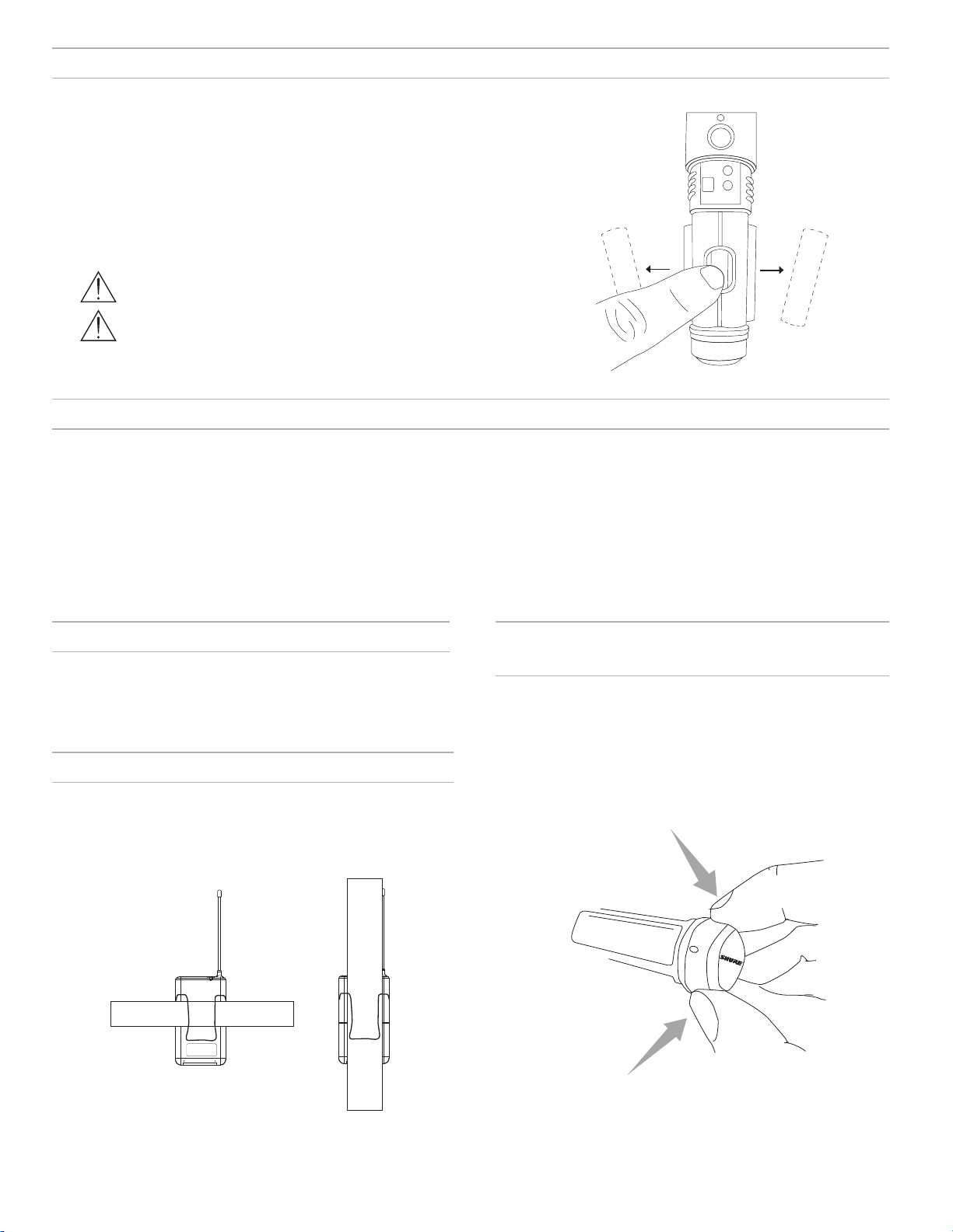
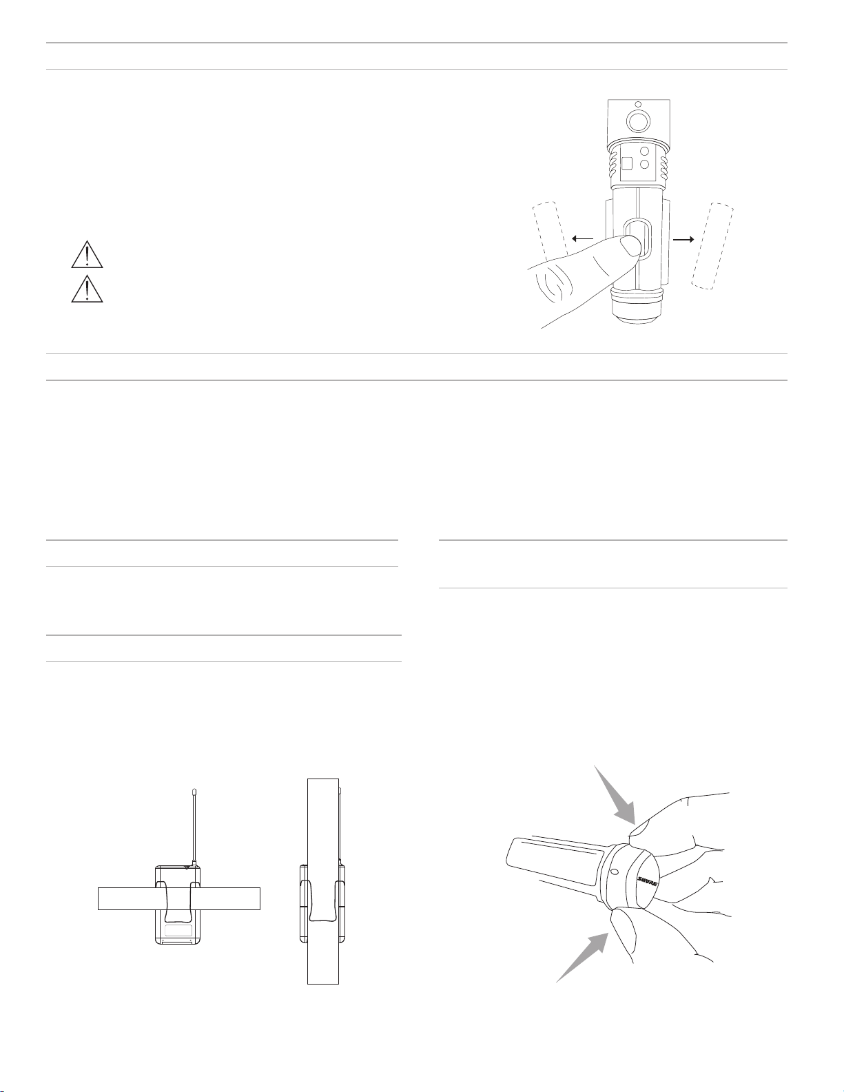
To remove batteries from the handheld transmitter, push them out through the opening in the
microphone battery compartment.
WARNING: Danger of explosion if battery incorrectly
replaced. Operate only with Shure compatible batteries.
WARNING: Battery packs shall not be exposed to ex-
cessive heat such as sunshine, fire, or the like.
Locking and Unlocking Controls
Lock system controls to prevent accidental setting changes or power-off.
Transmitter (lock/unlock)
Turn the transmitter on. Hold the group button, then press the channel
button for approximately 2 seconds. The LED indicator rapidly flashes
red when locked.
Power Off
Press and hold the power button to power off the BLX2 or BLX4R. To
power off the BLX1, slide the power switch to OFF.
Wearing the Bodypack Transmitter
Clip the transmitter to a belt or slide a guitar strap through the transmitter
clip as shown.
For best results, the belt should be pressed against the base of the clip.
Receiver (lock/unlock)
Turn the receiver on. Simultaneously hold the group and channel button until the flashing lock icon appears in the lower left-hand corner of
the display, indicating the controls are locked. Repeat to unlock the
controls.
Removing and Installing Identification
Caps
The BLX2 is equipped with a black identification cap from the factory
(dual vocal systems ship with additional gray cap).
To remove: Remove battery cover. Squeeze sides and pull off cap.
To install: Align the cap and click into place. Replace battery cover.
An Identification Cap Kit containing assorted colored caps is available
as an optional accessory.
13
Page 14
ANTENNA B
POWER
MIC OUT LINE OUT ANTENNA A
SHURE INCORPORATED
NILES, IL 60714
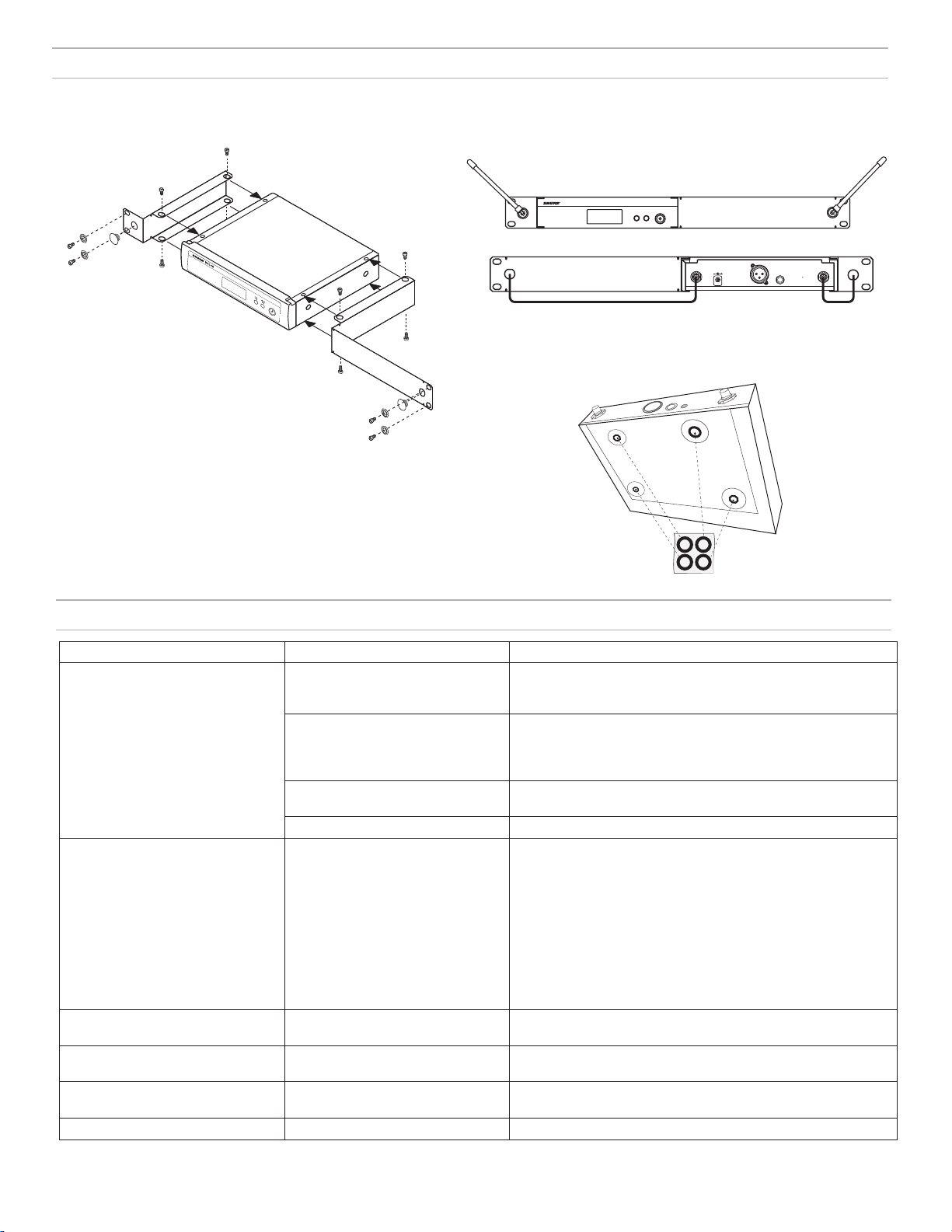
Rack-Mounting a Receiver
Use the supplied mounting hardware to install the receiver in a standard 19" audio equipment rack.
Troubleshooting
BXL4R
group channel
(A-Y) (0-9)
POWER
ANTENNA B
Antenna Connection
Diagram
SHURE INCORPORATED
NILES, IL 60714
MIC OUT LINE OUT ANTENNA A
Issue Indicator Status Solution
No sound or faint sound Receiver RF bars and battery LED
illuminated
• Verify all sound system connections or adjust gain as needed (see
Adjusting Gain)
• Verify that the receiver is connected to mixer/amplifier
Receiver RF bars and battery LED off • Turn on transmitter
• Make sure the batteries are installed correctly
• Perform transmitter setup (see Single System Setup)
• Insert fresh batteries
Receiver screen off • Make sure AC adapter is securely plugged into electrical outlet.
• Make sure receiver is powered on.
Transmitter indicator LED flashing red Replace transmitter batteries (see Changing Batteries).
Audio artifacts or dropouts Receiver RF bars and battery LED
flickering
• Change receiver and transmitter to a different group and/or
channel.
• Identify nearby sources of RF interference, and shutdown or remove source.
• Replace transmitter batteries.
• Ensure that receiver and transmitter are positioned within system
parameters
• System must be set up within recommended range and receiver
kept away from metallic surfaces.
• Transmitter must be used in line of sight from receiver for optimal
sound
Distortion Audio meter on receiver indicates
Reduce transmitter gain (see Adjusting Gain).
overload (OL)
Sound level variations when switching
N/A Adjust transmitter gain as necessary (see Adjusting Gain).
to different sources
Receiver/transmitter won't turn off LED indicator flashing rapidly, lock
See Locking and Unlocking Controls.
icon shown on receiver display
Transmitter beyond receiver range Receiver display dimmed to 50% Move transmitter closer to receiver
14
Page 15
Specifications
System
Working Range
91 m (300 ft) Line of Sight
Note: Actual range depends on RF signal absorption, reflection and interference.
Audio Frequency Response
50 to 15,000 Hz
Note: Dependent on microphone type
Total Harmonic Distortion
Ref. ±33 kHz deviation with 1 kHz tone
0.5%, typical
Dynamic Range
100 dB, A-weighted, typical
Operating Temperature
-18°C (0°F) to 57°C (135°F)
Note: Battery characteristics may limit this range.
Polarity
Positive pressure on microphone diaphragm (or positive voltage applied to tip of WA302 phone plug) produces positive voltage on pin 2
(with respect to pin 3 of low-impedance output) and the tip of the high
impedance 1/4-inch output.
BLX1
Audio Input Level
gain position max -16 dBV maximum
min (0 dB) +10 dBV maximum
Gain Adjustment Range
26 dB
Input Impedance
1 MΩ
RF Transmitter Output
10 mW, typical
varies by region
Dimensions
110 mm X 64 mm X 21 mm H x W x D
Weight
75 g (2.6 oz.), without batteries
Housing
Molded ABS
Power Requirements
2 LR6 AA batteries, 1.5 V, alkaline
Battery Life
up to 14 hours (alkaline)
BLX2
Audio Input Level
gain position 0dB -20 dBV maximum
-10dB -10 dBV maximum
Gain Adjustment Range
10 dB
RF Transmitter Output
10 mW, typical
varies by region
Dimensions
224 mm X 53 mm L x Dia.
Weight
218 g (7.7 oz.) (without batteries)
Housing
Molded ABS
Power Requirements
2 LR6 AA batteries, 1.5 V, alkaline
Battery Life
up to 14 hours (alkaline)
BLX4R
Output Impedance
XLR connector 200 Ω
6.35 mm (1/4") connec-
tor
Audio Output Level
Ref. ±33 kHz deviation with 1 kHz tone
XLR connector –20.5 dBV (into 100 kΩ load)
6.35 mm (1/4") connec-
tor
RF Sensitivity
-105 dBm for 12 dB SINAD, typical
Image Rejection
>50 dB, typical
Dimensions
50 mm X 198 mm X 163 mm H x W x D
Weight
without antennas
998 g (2.2 lb.)
Housing
Molded ABS, steel
Power Requirements
12–15 V DC @ 260 mA, supplied by external power supply (tip positive)
50 Ω
–13 dBV (into 100 kΩ load)
15
Page 16

Certifications
This Class B digital apparatus complies with Canadian ICES-003. Cet appareil numérique de la classe B est conforme à la norme NMB-003 du Canada.
Meets requirements of the following standards: EN 300 422 Parts 1 and 2, EN 301 489 Parts 1 and 9, EN60065.
Meets essential requirements of the following European Directives:
• R&TTE Directive 99/5/EC
• WEEE Directive 2002/96/EC, as amended by 2008/34/EC
• RoHS Directive 2002/95/EC, as amended by 2008/35/EC
Note: Please follow your regional recycling scheme for batteries and electronic waste
Approved under the Declaration of Conformity (DoC) provision of FCC Part 15.
Certified by IC in Canada under RSS-123 and RSS-102.
Certified under FCC Part 74.
Certified by IC in Canada under RSS-123 and RSS-102.
FCC ID: DD4BLX1A, DD4BLX1B, DD4BLX1C, DD4BLX1D; DD4BLX2A, DD4BLX2B, DD4BLX2C, DD4BLX2D. IC: 616A-BLX1A, 616A-BLX1B,
616A-BLX1C, 616A-BLX1D; 616A-BLX2A, 616A-BLX2B, 616A-BLX2C, 616A-BLX2D
This device complies with Industry Canada licence-exempt RSS standard(s). Operation of this device is subject to the following two conditions: (1) this
device may not cause interference, and (2) this device must accept any interference, including interference that may cause undesired operation of the
device.
Le présent appareil est conforme aux CNR d'Industrie Canada applicables aux appareils radio exempts de licence. L'exploitation est autorisée aux deux
conditions suivantes : (1) l'appareil ne doit pas produire de brouillage, et (2) l'utilisateur de l'appareil doit accepter tout brouillage radioélectrique subi,
même si le brouillage est susceptible d'en compromettre le fonctionnement.
The CE Declaration of Conformity can be obtained from Shure Incorporated or any of its European representatives. For contact information please visit
www.shure.com
The CE Declaration of Conformity can be obtained from: www.shure.com/europe/compliance
Authorized European representative:
Shure Europe GmbH
Headquarters Europe, Middle East & Africa
Department: EMEA Approval
Jakob-Dieffenbacher-Str. 12
75031 Eppingen, Germany
Phone: 49-7262-92 49 0
Fax: 49-7262-92 49 11 4
Email: EMEAsupport@shure.de
LICENSING INFORMATION
Licensing: A ministerial license to operate this equipment may be required in certain areas. Consult your national authority for possible requirements.
Changes or modifications not expressly approved by Shure Incorporated could void your authority to operate the equipment. Licensing of Shure wireless
microphone equipment is the user’s responsibility, and licensability depends on the user’s classification and application, and on the selected frequency.
Shure strongly urges the user to contact the appropriate telecommunications authority concerning proper licensing, and before choosing and ordering
frequencies.
Information to the user
This equipment has been tested and found to comply with the limits for a Class B digital device, pursuant to Part 15 of the FCC Rules. These limits are
designed to provide reasonable protection against harmful interference in a residential installation. This equipment generates uses and can radiate radio
frequency energy and, if not installed and used in accordance with the instructions, may cause harmful interference to radio communications. However,
there is no guarantee that interference will not occur in a particular installation. If this equipment does cause harmful interference to radio or television
reception, which can be determined by turning the equipment off and on, the user is encouraged to try to correct the interference by one or more of the
following measures:
• Reorient or relocate the receiving antenna.
• Increase the separation between the equipment and the receiver.
• Connect the equipment to an outlet on a circuit different from that to which the receiver is connected.
• Consult the dealer or an experienced radio/TV technician for help.
Note: EMC conformance testing is based on the use of supplied and recommended cable types. The use of other cable types may degrade EMC
performance.
Changes or modifications not expressly approved by the manufacturer could void the user’s authority to operate the equipment.
16
Page 17

Récepteur BLX4R
Panneau avant Panneau arrière
BLX4R
group channel
(A-Y) (0-9)
① LED des piles de l'émetteur
• Vert = durée de fonctionnement supérieure à une heure
• Rouge = durée de fonctionnement inférieure à une heure
② Écran LCD
Affiche les paramètres du récepteur et de
l'émetteur.
③ Bouton group
• Balayage : appuyer sur le bouton group
et le relâcher pour rechercher un groupe
et un canal ouverts
• Manuel : appuyer sur le bouton group
sans le relâcher pour sélectionner un
groupe.
ANTENNA B
21
3
④ Bouton channel
• Balayage : appuyer sur le bouton channel et
le relâcher pour rechercher un canal ouvert
• Manuel : appuyer sur le bouton channel sans
le relâcher pour sélectionner un canal.
⑤ Bouton d'alimentation
Met le récepteur sous tension et hors tension.
⑥ Jack d’antenne B
Connecteur BNC destiné à l'antenne B.
⑦ Prise d'alimentation c.c.
Destiné à une alimentation externe c.c. (12 à
15 V c.c.).
⑧ Serre-câble pour le cordon d'alimentation
Fixe le cordon d'alimentation au récepteur.
4
5 6
POWER
MIC OUT INSTRUMENT OUT VOLUME ANTENNA A
7
98
⑨ Prise de sortie audio XLR pour sortie
micro
Fournit une sortie audio niveau
microphone.
⑨ Prise de sortie audio pour sortie
instrument
Fournit un signal audio niveau instrument.
⑪ Commande de volume
Régler le niveau de sortie à l'aide d'un
tournevis.
⑫ Jack d’antenne A
Connecteur BNC destiné à l'antenne A.
1110
12
Écran LCD du récepteur
① Canal de télévision
Canal de télévision pour la fréquence sélectionnée.
② Verrouillage du récepteur
Indique que les commandes et l'alimentation sont verrouillées.
③ Groupe
Affiche le groupe sélectionné.
④ Canal
Affiche le canal sélectionné.
⑤ Intensité du signal RF
Le nombre de barres correspond à l'intensité du signal RF. OL
indique une surcharge de signal.
⑥ Vumètre audio
Le nombre de barres indique le niveau du signal audio. OL indique
l'écrêtage du signal.
⑦ Témoin d'antenne active
Indique l'antenne active pour le signal Diversity.
7
tv
1
2
group channel rf
3
4
AOLB
OL
audio
5 6
17
Page 18

Émetteurs
BLX1
① Témoin LED
Affiche l'état de l'alimentation et des piles (voir tableau).
② Interrupteur power
Met l'appareil sous tension ou hors tension.
③ Connecteur d’entrée à 4 broches du microphone (connecteur TA4)
④ Antenne
⑤ Bouton group
Modifie le réglage du groupe.
⑥ Affichage LED
Affiche le réglage du groupe et du canal.
⑦ Bouton channel
Modifie le réglage du canal.
⑧ Compartiment pile
⑨ Réglage du gain audio
Tourner pour augmenter ou réduire le gain de l'émetteur.
BLX2
① Témoin LED
Affiche l'état de l'alimentation et des piles (voir tableau).
② Bouton power
Appuyer dessus pour mettre l'appareil sous tension ou hors
tension.
③ Bouton group
Modifie le réglage du groupe.
④ Bouton channel
Modifie le réglage du canal et du gain.
⑤ Affichage LED
Affiche le réglage du groupe et du canal.
⑥ Capuchon d'identification
⑦ Compartiment pile
BLX1
BLX2
①
②
③
②
⑤
⑦
①
⑦
⑥
-10 dB
④
⑤
group
channel
③
④
group
channel
(A-Y)
(0-9)
⑨
⑧
Témoins LED d'émetteur
Témoin LED État
Vert Prêt
Clignote rapidement en
rouge
Rouge continu Piles presque déchargées (autonomie inférieure
Clignote en rouge et
s'éteint
*Pour les piles alcalines seulement. Pour les piles rechargeables, le témoin rouge allumé en continu signifie que les piles sont déchargées.
18
Commandes verrouillées
à une heure*)
Énergie des piles épuisée (changer les piles
pour pouvoir allumer l’émetteur)
⑥
Page 19

Configuration d'un seul système
group
(A-Y)
Avant de commencer, éteindre tous les émetteurs et allumer tout appareil
(autres microphones ou systèmes de retour personnel) susceptible de
causer des parasites pendant le spectacle.
1. Appuyer sur le bouton group du récepteur et le relâcher.
Le récepteur recherche le groupe et le canal les plus libres.
Remarque : Pour arrêter le balayage, appuyer à nouveau sur le bouton group.
2. Allumer l'émetteur et modifier le groupe et le canal afin qu'ils correspondent à ceux du récepteur (voir la section Réglage du groupe et du canal
de l'émetteur).
Une fois le système configuré, effectuer un test audio et régler le gain si nécessaire.
Réglage du groupe et du canal de l'émetteur
Le groupe et le canal de l'émetteur doivent être réglés manuellement afin de correspondre à ceux du récepteur.
Groupe (lettre)
1. Appuyer sur le bouton group de l'émetteur et le relâcher pour
activer l'affichage. Appuyer de nouveau sur le bouton group et
l'affichage clignote.
2. Quand l'affichage clignote, appuyer de nouveau sur le bouton
group pour passer au réglage de groupe désiré.
Canal (chiffre)
Si le canal doit être modifié, suivre la même procédure en utilisant le bouton
channel au lieu du bouton group.
Remarque :
• Lorsque le groupe et le canal correspondent bien à ceux du récepteur,
les barres RF et la LED des piles du récepteur s'allument.
• Après la configuration manuelle, l'émetteur affiche en alternance le
réglage de groupe et de canal pendant environ deux secondes.
group
group
group
group channel
channel
channel
channel
19
Page 20

Configuration de plusieurs systèmes
Il est possible d'utiliser jusqu'à 12 systèmes simultanément (selon la disponibilité des bandes et des plages HF).
Important : Configurer chaque système un par un. Une fois qu'un récepteur et un émetteur sont réglés sur le même groupe et le même canal, laisser l'émetteur sous tension. Autrement, les balayages
effectués par les autres récepteurs ne permettront pas de détecter que ce canal est occupé.
Allumer tout autre appareil susceptible de causer des parasites pendant le spectacle de façon à ce qu'il soit détecté pendant les balayages de groupes et de canaux effectués lors des étapes suivantes.
Avant de commencer la configuration des systèmes, ALLUMER tous les récepteurs et ÉTEINDRE tous les émetteurs.
Pour le premier récepteur :
1. Effectuer un balayage de groupes pour trouver le groupe présentant le plus grand nombre de canaux libres.
2. Allumer le premier émetteur et modifier le groupe et le canal afin qu'ils correspondent à ceux du récepteur.
3. Laisser l'émetteur allumé et poursuivre en passant aux autres systèmes.
Remarque : Si le groupe sélectionné ne contient pas assez de canaux ouverts, sélectionner manuellement le groupe « d » lors de configuration de grands systèmes.
Pour chaque récepteur supplémentaire :
1. Modifier manuellement le récepteur afin que son réglage de groupe corresponde à celui du premier récepteur. Il ne faut pas oublier que, chaque fois
que le réglage de groupe est modifié, un balayage des canaux s'effectue automatiquement.
2. Allumer l'émetteur et modifier le groupe et le canal afin qu'ils correspondent à ceux du récepteur.
3. Laisser l'émetteur allumé et poursuivre en passant au système suivant.
4. Une fois tous les récepteurs configurés, effectuer un test audio de tous les microphones.
Réglage manuel du groupe et du canal du récepteur
Dans une configuration à plusieurs systèmes, il peut falloir changer le groupe du récepteur.
Groupe (lettre)
1. Maintenir enfoncé le bouton group du récepteur jusqu'à ce que l'affichage se mette à clignoter.
2. Quand l'affichage clignote, appuyer de nouveau sur le bouton group pour passer au groupe suivant.
Remarque : Seul le réglage du groupe s'affiche pendant l'opération de configuration manuelle.
3. Une fois le groupe désiré atteint, relâcher le bouton group. Le récepteur effectue automatiquement un balayage des canaux.
Canal (chiffre)
Toujours utiliser un canal sélectionné par le balayage des canaux. Toutefois, si nécessaire, il est possible de régler le canal manuellement. Suivre la
procédure ci-dessus en utilisant le bouton channel au lieu du bouton group.
20
Page 21
group
(A-Y)
channel
(0-9)
13 mm
(.5 in.)
Conseils pour améliorer les performances du système sans fil
En cas de parasites ou de pertes de signal, essayer les mesures suivantes :
• Choisir un autre canal de récepteur
• Repositionner le récepteur de façon à ce qu'aucun obstacle
ne se trouve dans la ligne de visée de l'émetteur (y compris le
public)
• Éviter de placer l'émetteur et le récepteur à des endroits où du
métal ou des matériaux denses sont présents
• Placer le récepteur en haut du rack de matériel
• Éliminer toutes les sources proches de parasites de matériel sans fil,
telles que téléphones portables, radios bidirectionnelles, ordinateurs,
lecteurs multimédia, appareils Wi-Fi et processeurs de signal numérique
• Charger ou remplacer l'accu de l'émetteur
• Laisser plus de deux mètres (6 pieds) entre les émetteurs
• Laisser plus de 5 mètres (16 pieds) entre l'émetteur et le récepteur
• Pendant la vérification du son, repérer les zones à problème et
demander aux présentateurs ou aux artistes d'éviter ces zones
Comment obtenir une bonne qualité sonore
Placement correct du microphone
• Maintenir le microphone dans un rayon de 12 pouces autour de la source sonore. Pour
obtenir un son plus chaud avec une présence accrue des basses, rapprocher le microphone.
• Ne pas couvrir la grille avec la main.
Port du microphone sur casque
• Placer le microphone sur casque à 13 mm (1/2 po) du coin de la bouche.
• Positionner les micros-cravates et les microphones sur casque de façon à éviter tout heurt ou
frottement contre les vêtements, les bijoux ou d'autres éléments.
Réglage du gain
Surveiller le vumètre sur l'affichage du récepteur lors du réglage du gain de l'émetteur. Le témoin OL ne doit s'allumer que rarement, quand on parle fort
ou quand le son de l'instrument est fort.
BLX1
Tourner le bouton de réglage du gain audio pour augmenter (+)
ou réduire (–) le gain jusqu'au niveau souhaité.
Pour les instruments, mettre le gain au réglage minimum. Pour
les micros-cravates, augmenter le gain au niveau désiré.
BLX2
Le BLX2 comporte deux réglages du niveau de gain :
•
Réglage par défaut
• -10 dB
Utiliser le réglage par défaut dans
la plupart des cas. Si le témoin OL
d'audio du récepteur s'affiche souvent, régler le micro à -10 dB.
1. Pour régler le gain a -10 dB,
maintenir le bouton channel enfoncé jusqu'à ce qu'un petit point
apparaisse dans le coin inférieur
droit de l'affichage de l'émetteur.
2. Pour revenir au réglage par défaut du gain, maintenir le bouton
channel jusqu'à ce que le point
disparaisse.
group
-10 dB
channel
-10 dB
group
5 s
channel
21
Page 22
Piles
L’autonomie estimée des piles AA peut aller jusqu'à 14 heures (l'autonomie totale des piles
dépend de leur type et de leur fabricant).
Lorsque le témoin LED devient rouge, cela signifie que les piles sont « presque déchargées » et
qu'il leur reste environ 60 minutes d'autonomie.
Pour les piles alcalines seulement. Pour les piles rechargeables, le témoin rouge allumé en continu signifie que les piles sont
déchargées.
Pour retirer les piles de l'émetteur main, les extraire en les poussant par l'ouverture du compartiment pile du microphone.
AVERTISSEMENT : Danger d'explosion si l'accu
est mal placé. N'utiliser qu'avec des accus compatibles
Shure.
AVERTISSEMENT : Les accus ne doivent pas être
exposés à une chaleur excessive, p. ex. lumière du soleil,
feu ou similaire.
Verrouillage et déverrouillage des commandes
Verrouiller les commandes du système pour éviter de modifier les réglages ou de mettre le système hors tension accidentellement.
Émetteur (verrouiller/déverrouiller)
Allumer l'émetteur. Maintenir enfoncé le bouton group, puis appuyer sur
le bouton channel pendant environ 2 secondes. Le témoin LED clignote
rapidement en rouge une fois verrouillé.
Mise hors tension
Appuyer sans relâcher sur le bouton power pour éteindre le BLX2 ou le
BLX4R. Pour éteindre le BLX1, mettre l'interrupteur d'alimentation sur
OFF.
Port de l’émetteur de poche
Accrocher l’émetteur à une ceinture ou glisser une sangle de guitare
dans l’attache de l’émetteur comme illustré.
Pour obtenir les meilleurs résultats, la ceinture doit être appuyée contre
la base de l’attache.
Récepteur (verrouiller/déverrouiller)
Mettre le récepteur sous tension. Appuyer simultanément sur le bouton
group et le bouton channel jusqu'à ce que l'icône de cadenas clignotante apparaisse dans le coin inférieur gauche de l'affichage, indiquant
que les commandes sont verrouillées. Répéter pour déverrouiller les
commandes.
Retrait et mise en place des capuchons
d'identification
Le BLX2 est équipé en usine d'un capuchon d'identification noir (les
systèmes doubles pour la voix sont fournis avec un capuchon supplémentaire de couleur grise).
Retrait : Enlever le couvercle du compartiment pile. Presser sur les cô-
tés du capuchon pour l'extraire.
Mise en place : Aligner le capuchon et le mettre en place avec un déclic.
Remettre le couvercle du compartiment pile.
Un kit de capuchons d'identification contenant un assortiment de capuchons colorés est disponible comme accessoire en option.
22
Page 23

ANTENNA B
POWER
MIC OUT LINE OUT ANTENNA A
SHURE INCORPORATED
NILES, IL 60714
Montage en rack d'un récepteur
Installer le récepteur dans un rack de matériel audio 19 po standard à l'aide des pièces de montage fournies.
Dépannage
Problème État du témoin Solution
Son faible ou inexistant Les barres RF et la LED des piles du
récepteur sont allumées
Les barres RF et la LED des piles du
récepteur sont éteintes
Écran du récepteur éteint • S'assurer que l'adaptateur c.a. est solidement branché sur une prise
Témoin LED de l’émetteur clignotant
en rouge
Artéfacts audio ou pertes de signal Les barres RF et la LED des piles du
récepteur clignotent
Distorsion Le vumètre du récepteur indique une
surcharge (OL)
Variations du niveau sonore lors du
N/A Réduire le gain de l’émetteur selon le besoin (voir Réglage du gain).
passage à d'autres sources
Impossible d'éteindre le récepteur
ou l'émetteur
Le témoin LED clignote rapidement,
l'icône de cadenas est affichée sur
l'affichage du récepteur
Émetteur hors portée du récepteur Luminosité de l'affichage du récepteur
réduite à 50 %
• Vérifier tous les branchements de la sonorisation ou régler le gain
selon le besoin (voir la section Réglage du gain)
• Vérifier que le récepteur est raccordé au mélangeur/amplificateur
• Allumer l'émetteur
• S'assurer que les piles sont bien en place
• Effectuer la mise en service de l’émetteur (voir la section Mise en service d’un système unique)
• Insérer des piles neuves
électrique.
• S'assurer que le récepteur est sous tension.
Remplacer les piles de l'émetteur (voir Remplacement des piles).
• Faire passer le récepteur et l’émetteur à un groupe et/ou canal
différents.
• Identifier les sources proches de parasites HF et les éteindre ou les
éliminer.
• Remplacer les piles de l'émetteur.
• S'assurer que le récepteur et l'émetteur sont positionnés dans les limites des paramètres du système
• Le système doit être configuré dans la plage recommandée et le récepteur éloigné des surfaces métalliques.
• L'émetteur doit être utilisé dans la ligne de visée du récepteur pour
obtenir un son optimal
Réduire le gain de l’émetteur (voir Réglage du gain).
Voir Verrouillage et déverrouillage des commandes.
Rapprocher l'émetteur du récepteur
BXL4R
group channel
(A-Y) (0-9)
Schéma de connexion
des antennes
POWER
ANTENNA B
SHURE INCORPORATED
NILES, IL 60714
MIC OUT LINE OUT ANTENNA A
23
Page 24

Caractéristiques
Système
Plage de fonctionnement
91 m (300 pi) Ligne de visée
Remarque : La portée réelle dépend de l'absorption et de la réflexion des signaux HF, ainsi
que des parasites.
Réponse en fréquence audio
50 à 15,000 Hz
Remarque : dépend du type de microphone
Distorsion harmonique totale
Réf. ±33 kHz de déviation avec 1 kHz de tonalité
0,5%, typique
Plage dynamique
100 dB, pondéré en A, typique
Température de fonctionnement
-18°C (0°F) à 57°C (135°F)
Remarque : Les caractéristiques des piles peuvent limiter cette plage.
Polarité
Une pression positive sur le diaphragme du microphone (ou une tension positive appliquée à la pointe du jack téléphone WA302) produit
une tension positive à la broche 2 (par rapport à la broche 3 de la
sortie basse impédance) et à la pointe de la sortie haute impédance
de 1/4 po.
BLX1
Niveau d’entrée audio
position de gain max -16 dBV maximum
min (0 dB) +10 dBV maximum
Plage de réglage de gain
26 dB
Impédance d’entrée
1 MΩ
Sortie HF de l’émetteur
10 mW, typique
varie suivant la région
Dimensions
110 mm X 64 mm X 21 mm H x L x P
Poids
75 g (2,6 oz), sans piles
Boîtier
ABS moulé
Alimentation
2 LR6 Piles AA, 1,5 V, Alcaline
Autonomie des piles
jusqu'à 14 heures (Alcaline)
BLX2
Niveau d’entrée audio
position de gain 0dB -20 dBV maximum
-10dB -10 dBV maximum
Plage de réglage de gain
10 dB
Sortie HF de l’émetteur
10 mW, typique
varie suivant la région
Dimensions
224 mm X 53 mm L x diam.
Poids
218 g (7,7 oz.) (sans piles)
Boîtier
ABS moulé
Alimentation
2 LR6 Piles AA, 1,5 V, Alcaline
Autonomie des piles
jusqu'à 14 heures (Alcaline)
BLX4R
Impédance de sortie
Connecteur XLR 200 Ω
Connecteur de 6,35 mm
(1/4 po)
Niveau de sortie audio
Réf. ±33 kHz de déviation avec 1 kHz de tonalité
Connecteur XLR –20.5 dBV (dans 100 kΩ de charge)
Connecteur de 6,35 mm
(1/4 po)
Sensibilité HF
-105 dBm pour 12 dB SINAD, typique
Suppression de la fréquence image
>50 dB, typique
Dimensions
50 mm X 198 mm X 163 mm H x L x P
Poids
sans antennes
998 g (2,2 lb.)
Boîtier
ABS moulé, Stahl
Alimentation
12–15 V c.c. @ 260 mA, provenant d’un bloc d’alimentation externe
(pointe positive)
50 Ω
–13 dBV (dans 100 kΩ de charge)
24
Page 25

Homologations
Cet appareil numérique de la classe B est conforme à la norme ICES-003 du Canada. Cet appareil numérique de la classe B est conforme à la norme
NMB-003 du Canada.
Conforme aux exigences des normes suivantes : EN 300 422 parties 1 et 2., EN 301 489 parties 1 et 9, EN60065.
Conforme aux exigences essentielles des directives européennes suivantes :
• Directive R&TTE 99/5/CE
• Directive DEEE 2002/96/CE, telle que modifiée par 2008/34/CE
• Directive RoHS 2002/95/CE, telle que modifiée par 2008/35/CE
Remarque : Suivre le plan de recyclage régional en vigueur pour les accus et les déchets électroniques
Approuvé selon la déclaration de conformité de la partie 15 des réglementations FCC.
Homologué par IC au Canada selon RSS-123 et RSS-102.
Homologué selon la partie 74 des réglementations FCC.
Homologué par IC au Canada selon RSS-123 et RSS-102.
Code FCC : DD4BLX1A, DD4BLX1B, DD4BLX1C, DD4BLX1D; DD4BLX2A, DD4BLX2B, DD4BLX2C, DD4BLX2D. IC : 616A-BLX1A, 616A-BLX1B,
616A-BLX1C, 616A-BLX1D; 616A-BLX2A, 616A-BLX2B, 616A-BLX2C, 616A-BLX2D
Cet appareil est conforme à la ou aux normes RSS d'exemption de licence d'Industrie Canada. L'utilisation de ce dispositif est assujettie aux deux condi-
tions suivantes : (1) ce dispositif ne doit pas causer d’interférences et (2) ce dispositif doit accepter toutes les interférences, y compris celles qui pourraient provoquer un fonctionnement non souhaitable de l’appareil.
Le présent appareil est conforme aux CNR d'Industrie Canada applicables aux appareils radio exempts de licence. L'exploitation est autorisée aux deux
conditions suivantes : (1) l'appareil ne doit pas produire de brouillage, et (2) l'utilisateur de l'appareil doit accepter tout brouillage radioélectrique subi,
même si le brouillage est susceptible d'en compromettre le fonctionnement.
La déclaration de conformité CE peut être obtenue auprès de Shure Incorporated ou de ses représentants européens. Pour les coordonnées, visiter
www.shure.com
La déclaration de conformité CE peut être obtenue auprès de : www.shure.com/europe/compliance
Représentant agréé européen :
Shure Europe GmbH
Siège Europe, Moyen-Orient et Afrique
Service : Homologation EMA
Jakob-Dieffenbacher-Str. 12
75031 Eppingen, Allemagne
Téléphone : 49-7262-92 49 0
Télécopie : 49-7262-92 49 11 4
Courriel : EMEAsupport@shure.de
RENSEIGNEMENTS SUR L'OCTROI DE LICENCE
Autorisation d'utilisation : Une licence officielle d'utilisation de ce matériel peut être requise dans certains pays. Consulter les autorités compétentes pour
les exigences éventuelles. Tout changement ou modification n'ayant pas fait l'objet d'une autorisation expresse de Shure Incorporated peut entraîner
la nullité du droit d'utilisation de l'équipement. La licence d’utilisation de l'équipement de microphone sans fil Shure demeure de la responsabilité de
l'utilisateur, et dépend de la classification de l'utilisateur et de l'application prévue par lui ainsi que de la fréquence sélectionnée. Shure recommande
vivement de se mettre en rapport avec les autorités compétentes des télécommunications pour l'obtention des autorisations nécessaires, et ce avant de
choisir et de commander des fréquences.
Information à l'utilisateur
Cet équipement a été testé et déclaré conforme aux limites pour les appareils numériques de classe B, selon la section 15 des règlements de la FCC.
Ces limites sont destinées à assurer une protection raisonnable contre les interférences nuisibles dans une installation résidentielle. Cet équipement
produit, utilise et peut émettre de l'énergie radio électrique et, s'il n'est pas installé et utilisé conformément aux présentes instructions, peut causer des
interférences nuisibles aux communications radio. Il n'existe toutefois aucune garantie que de telles interférences ne se produiront pas dans une installation particulière. Si cet équipement produit des interférences nuisibles à la réception d'émissions de radio ou de télévision, ce qui peut être établi en
mettant l'appareil sous, puis hors tension, il est recommandé à l'utilisateur d'essayer de corriger le problème en prenant l'une ou plusieurs des mesures
suivantes :
• Réorienter ou déplacer l'antenne réceptrice.
• Augmenter la distance séparant l'équipement du récepteur.
• Brancher l'équipement sur un circuit électrique différent de celui du récepteur.
• Consulter le distributeur ou un technicien radio et télévision.
Remarque : Les essais de conformité CEM sont basés sur l'utilisation de types de câbles fournis et recommandés. L’utilisation d'autres types de câble peut dégrader la performance CEM.
Tout changement ou modification n'ayant pas fait l'objet d'une autorisation expresse du fabricant peut entraîner la nullité du droit d'utilisation de l'équipement.
25
Page 26

BLX4R Empfänger
BLX4R
Vorderseite Rückseite
group channel
(A-Y) (0-9)
① Senderakku-LED
• Grün = Laufzeit mehr als 1 Stunde
• Rot = Laufzeit weniger als 1 Stunde
② LCD-Anzeige
Zeigt Empfänger- und Sendereinstellungen
an.
③ Taste group
• Scan: Die group-Taste kurz drücken,
um nach einer freien Gruppe und einem
freien Kanal zu suchen.
• Manuell: Die group-Taste gedrückt
halten, um eine Gruppe auszuwählen.
ANTENNA B
21
3
④ Taste channel
• Scan: Die channel-Taste kurz drücken, um
nach einem freien Kanal zu suchen.
• Manuell: Die channel-Taste gedrückt halten,
um einen Kanal auszuwählen.
⑤ An/Aus-Taste
Schaltet den Empfänger an und aus.
⑥ Antennenbuchse B
BNC-Anschluss für Antenne B.
⑦ Gleichstrombuchse
Für externes Gleichstromnetzteil (12 bis 15 V
Gleichspannung).
4
5 6
POWER
MIC OUT INSTRUMENT OUT VOLUME ANTENNA A
7
98
⑧ Zugentlastungsschleife für Netzkabel
Sichert das Netzkabel am Empfänger.
⑨ Mic Out XLR-Audio-Ausgangsbuchse
Versorgt Mikrofonpegel-Audioausgang.
⑨ INST Out Audio-Ausgangsbuchse
Liefert das Instrumentpegel-Audiosignal.
⑪ Lautstärkeregler
Der Ausgangspegel wird mit einem
Schraubendreher eingestellt.
⑫ Antennenbuchse A
BNC-Anschluss für Antenne A.
1110
12
LCD-Anzeige des Empfängers
① Fernsehkanal
Fernsehkanal für die ausgewählte Frequenz.
② Sperrung des Empfängers
Zeigt an, dass die Sperre der Bedienelemente und des An/AusSchalters aktiviert ist.
③ group
Zeigt die ausgewählte Gruppe an.
④ channel
Zeigt den ausgewählten Kanal an.
⑤ HF-Signalfeldstärke
Anzahl der Balken entspricht der HF-Signalstärke. OL zeigt
Übersteuerung an.
⑥ Audio-Pegelanzeige
Anzahl der Balken entspricht der Audiosignalstärke. OL zeigt
Signalbegrenzung an.
⑦ Anzeige für aktive Antenne
Zeigt die aktive Antenne für das Diversity-Signal an.
7
1
2
tv
group channel rf
3
4
AOLB
OL
audio
5 6
26
Page 27

Sender
BLX1
① LED-Anzeige
Zeigt den Netz- und Akkustatus an (siehe Tabelle).
② Schalter power
Schaltet die Stromversorgung an und aus.
③ 4-polige Mikrofon-Eingangsbuchse (TA4-Buchse)
④ Antenne
⑤ Taste group
Ändert die Gruppeneinstellung.
⑥ LED-Anzeige
Zeigt die Gruppen- und Kanaleinstellungen an.
⑦ Taste channel
Ändert die Kanaleinstellung.
⑧ Akku-/Batteriefach
⑨ Audio-Gain-Einstellung
Drehen, um die Eingangsverstärkung (Gain) am Sender zu erhöhen
oder verringern.
BLX2
① LED-Anzeige
Zeigt den Netz- und Akkustatus an (siehe Tabelle).
② Taste power
Drücken, um die Stromversorgung an- bzw. auszuschalten.
③ Taste group
Ändert die Gruppeneinstellung.
④ Taste channel
Ändert die Kanal- und Gain-Einstellung.
⑤ LED-Anzeige
Zeigt die Gruppen- und Kanaleinstellungen an.
⑥ Kennzeichnungskappe
⑦ Akku-/Batteriefach
BLX1
BLX2
①
②
③
②
⑤
⑦
①
⑦
⑥
-10 dB
④
⑤
group
channel
③
④
group
channel
(A-Y)
(0-9)
⑨
⑧
Sender-LED-Anzeigen
LED-Anzeige Status
Grün Bereit
Schnell rot blinkend Bedienelemente gesperrt
Ständig rot Batteriestand niedrig (weniger als 1 Stunde
Rot blinkend und
schaltet sich ab
*Nur bei Alkalibatterien. Bei wiederaufladbaren Akkus bedeutet ständig rot, dass die Akkus entladen sind.
Laufzeit*)
Batterien/Akkus entladen (Batterien/Akkus er-
setzen, um Sender einzuschalten)
⑥
27
Page 28

Einrichten von Einzelsystemen
group
(A-Y)
Zunächst alle Sender ausschalten und alle Geräte (andere Mikrofone oder
In-Ear-Abhörsysteme) einschalten, die während der Vorstellung Störungen
verursachen könnten.
1. Die group-Taste auf dem Empfänger kurz drücken.
Der Empfänger führt einen Scan durch, um Gruppe und Kanal zu finden,
die am ungestörtesten sind.
Hinweis: Falls der Scan gestoppt werden soll, die group-Taste noch einmal
drücken.
2. Den Sender einschalten und Gruppe und Kanal entsprechend der
Empfängereinstellung einstellen (siehe Einstellen von Sendergruppe und
-kanal).
Nachdem das System eingestellt ist, einen Klangtest durchführen und das Gain
nach Bedarf einstellen.
Einstellen von Sendergruppe und -kanal
Gruppe und Kanal des Senders müssen manuell auf die gleiche Gruppe und den gleichen Kanal wie der Empfänger eingestellt werden.
Gruppe (Buchstabe)
1. Die group-Taste auf dem Sender kurz drücken, um die Anzeige
zu aktivieren. Die group-Taste noch einmal drücken; die Anzeige
blinkt.
2. Während die Anzeige blinkt, die group-Taste noch einmal drücken, um zur gewünschten Gruppeneinstellung zu gelangen.
Kanal (Nummer)
Falls der Kanal geändert werden muss, ebenso vorgehen wie oben, jedoch die
channel-Taste anstelle der group-Taste verwenden.
Hinweis:
• Wenn Gruppe und Kanal mit dem Empfänger übereinstimmen, leuchten
die HF-Balken und die Akku-LED auf dem Empfänger.
• Nach der manuellen Einrichtung zeigt der Sender ca. zwei Sekunden
lang abwechselnd die Gruppen- und Kanaleinstellungen an.
group
group
group
group channel
channel
channel
channel
28
Page 29

Einrichten mehrerer Systeme
Es können bis zu 12 Systeme gleichzeitig betrieben werden (abhängig von Band und HF-Umgebung).
Wichtig: Die Systeme müssen eines nach dem anderen eingerichtet werden. Nachdem ein Empfänger und Sender auf die gleiche Gruppe und den gleichen Kanal eingestellt wurden, muss der Sender
eingeschaltet bleiben. Andernfalls werden Scans der anderen Empfänger diesen Kanal nicht als belegt erkennen.
Alle anderen digitalen Geräte einschalten, die während der Vorstellung Störungen verursachen könnten, damit diese bei den folgenden Schritten während der Gruppen- und Kanalscans erkannt
werden.
Vor Beginn der Systemeinrichtung alle Empfänger auf EIN und alle Sender auf AUS schalten.
Für den ersten Empfänger:
1. Einen Group Scan durchführen, um die Gruppe mit den meisten freien Kanälen zu finden.
2. Den ersten Sender einschalten und Gruppe und Kanal entsprechend der Empfängereinstellung einstellen.
3. Den Sender eingeschaltet lassen und weitere Systeme einrichten.
Hinweis: Falls die ausgewählte Gruppe nicht genug freie Kanäle enthält, manuell Gruppe „d“ auswählen, wenn größere Systeme eingerichtet werden.
Für jeden weiteren Empfänger:
1. Den Empfänger manuell auf die Gruppeneinstellung des ersten Empfängers einstellen. Es ist zu beachten, dass bei jeder Änderung der
Gruppeneinstellung automatisch ein Channel Scan durchgeführt wird.
2. Den Sender einschalten und Gruppe und Kanal entsprechend der Empfängereinstellung einstellen.
3. Den Sender eingeschaltet lassen und das nächste System einrichten.
4. Nachdem alle Empfänger eingerichtet sind, an allen Mikrofonen einen Klangtest durchführen.
Manuelles Einstellen von Empfängergruppe und -kanal
Die Empfängergruppe muss beim Einrichten mehrerer Systeme eventuell geändert werden.
Gruppe (Buchstabe)
1. Die group-Taste auf dem Empfänger gedrückt halten, bis die Anzeige zu blinken beginnt.
2. Während die Anzeige blinkt, die group-Taste noch einmal drücken, um zur nächsten Gruppe zu wechseln.
Hinweis: Beim manuellen Einrichten wird nur die Gruppeneinstellung angezeigt.
3. Nachdem die gewünschte Gruppe erreicht ist, die group-Taste loslassen. Der Empfänger führt automatisch einen Channel Scan durch.
Kanal (Nummer)
Immer einen Kanal verwenden, der durch den Channel Scan ausgewählt wurde. Bei Bedarf kann der Kanal allerdings manuell eingestellt werden. Dabei
ebenso vorgehen wie oben, jedoch die channel-Taste anstelle der group-Taste verwenden.
29
Page 30

group
(A-Y)
channel
(0-9)
13 mm
(.5 in.)
Hinweise zum Verbessern der Systemleistung bei Drahtlossystemen
Falls Funkstörungen oder Aussetzer der Übertragung auftreten, Folgendes versuchen:
• Einen anderen Empfangskanal auswählen.
• Den Empfänger anders platzieren, so dass die Sichtverbindung
zum Sender durch nichts verdeckt wird (einschließlich
Publikum).
• Den Sender und den Empfänger nicht in der Nähe von Metall
oder anderen dichten Materialien aufstellen.
• Den Empfänger auf die oberste Etage des Geräte-Racks
umsetzen.
• Nahe gelegene Drahtlosfunkstörungsquellen, wie z. B. Handys,
Funksprechgeräte, Computer, Medienabspielgeräte, Wi-Fi-Geräte und
digitale Signalprozessoren, entfernen.
• Den Akku des Senders laden oder ersetzen.
• Sender mehr als zwei Meter voneinander entfernt halten.
• Den Sender und den Empfänger mehr als 5 Meter voneinander entfernt
halten.
• Während des Klangtests „Problemstellen“ markieren und die
Vortragenden oder Ausführenden bitten, diese Bereiche zu vermeiden.
Erzielung guter Tonqualität
Korrekte Mikrofonplatzierung
• Das Mikrofon maximal 30 cm von der Tonquelle entfernt halten. Für einen wärmeren Klang
mit stärkerer Basspräsenz das Mikrofon näher heranrücken.
• Den Grill nicht mit der Hand verdecken.
Tragen des Kopfbügelmikrofons
• Das Kopfbügelmikrofon etwa 13 mm vom Mundwinkel entfernt platzieren.
• Lavalier- und Kopfbügelmikrofone so platzieren, dass Kleidung, Schmuck oder andere
Gegenstände nicht am Mikrofon anschlagen oder daran reiben.
Einstellen der Verstärkung
Die Audio-Pegelanzeige auf der Empfängeranzeige beobachten, während die Eingangsverstärkung (Gain) am Sender eingestellt wird. Die OL-Anzeige
darf nur gelegentlich leuchten, wenn laut gesprochen oder das Instrument laut gespielt wird.
BLX1
Den Audio-Gain-Regler drehen, um das Gain zu erhöhen (+)
oder verringern (–), bis der gewünschte Pegel eingestellt ist.
Bei Instrumenten die Verstärkung auf die Mindesteinstellung
einstellen. Bei Lavalier-Mikrofonen die Verstärkung nach
Wunsch erhöhen.
BLX2
Das Modell BLX2 verfügt über zwei Verstärkungspegel-Einstellungen:
•
Voreinstellung
• -10 dB
Die Voreinstellung wird für die
meisten Situationen verwendet.
Falls die OL-Audioanzeige des
Empfängers häufig an ist, das
Mikrofon auf -10 dB einstellen.
1. Um das Gain auf -10 dB
einzustellen, die channel-Taste
gedrückt halten, bis ein kleiner
Punkt in der rechten, unteren
Ecke der Senderanzeige eingeblendet wird.
2. Um das Gain wieder auf den
Normalwert einzustellen,
die channel-Taste bis zum
Erlöschen des Punkts gedrückt
halten.
group
-10 dB
channel
-10 dB
group
channel
5 s
30
Page 31

Batterien/Akkus
Die Lebensdauer von AA-Batterien beträgt bis zu 14 Stunden (die Gesamtlebensdauer der
Batterie ist je nach Batterietyp und -hersteller unterschiedlich).
Wenn die LED-Anzeige rot aufleuchtet, bedeutet das „Batterie schwach“; normalerweise verbleiben dann ca. 60 Minuten Batterielebensdauer.
Nur für Alkalibatterien. Bei wiederaufladbaren Akkus bedeutet ständig rot, dass die Akkus entladen sind.
Um die Akkus/Batterien aus dem Handsender zu entfernen, diese durch die Öffnung im
Mikrofon-Batteriefach hinausdrücken.
ACHTUNG: Es besteht Explosionsgefahr, wenn die
Batterie nicht richtig ersetzt wird. Nur mit kompatiblen
Shure-Batterien betreiben.
ACHTUNG: Akkusätze dürfen keiner starken Hitze
wie Sonnenschein, Feuer oder dergleichen ausgesetzt
werden.
Sperren und Entsperren der Bedienelemente
Die Bedienelemente des Systems sperren, um das versehentliche Ändern der Einstellungen oder Ausschalten der Stromversorgung zu verhindern.
Sender (sperren/entsperren)
Den Sender anschalten. Die group-Taste gedrückt halten und danach
die channel-Taste ca. 2 Sekunden lang gedrückt halten. Die LEDAnzeige blinkt im gesperrten Zustand schnell rot.
Ausschalten
Zum Ausschalten des BLX2 oder BLX4R die power-Taste gedrückt
halten. Zum Ausschalten des BLX1 den An/Aus-Schalter auf OFF
schieben.
Tragen des Taschensenders
Den Sender an einem Gürtel festklemmen oder einen Gitarrengurt wie
abgebildet durch den Senderclip ziehen.
Für ein optimales Ergebnis muss der Gürtel an der Auflagefläche des
Clips anliegen.
Empfänger (sperren/entsperren)
Den Empfänger anschalten. Gleichzeitig die group- und channelTaste gedrückt halten, bis das blinkende Schloss-Symbol in der
unteren, linken Ecke der Anzeige eingeblendet wird; es gibt an, dass
die Bedienelemente gesperrt sind. Diesen Schritt zum Entsperren der
Bedienelemente wiederholen.
Entfernen und Anbringen der
Kennzeichnungskappen
Das Modell BLX2 ist ab Werk mit einer schwarzen
Kennzeichnungskappe ausgestattet (Doppelgesangssysteme werden
mit einer zusätzlichen grauen Kappe geliefert).
Entfernen: Die Akku-/Batteriefachabdeckung abnehmen. Die Seiten
zusammendrücken und die Kappe abziehen.
Anbringen: Die Kappe ausrichten und einrasten lassen. Die Akku-/
Batteriefachabdeckung wieder anbringen.
Ein Kennzeichnungskappensatz mit verschiedenfarbigen Kappen ist als Sonderzubehör
lieferbar.
31
Page 32

ANTENNA B
POWER
MIC OUT LINE OUT ANTENNA A
SHURE INCORPORATED
NILES, IL 60714
Rack-Montage eines Empfängers
Der Empfänger wird mit den mitgelieferten Befestigungsteilen in einem standardmäßigen 19-Zoll-Audiogeräterack montiert.
Störungssuche
Problem Anzeigestatus Abhilfe
Kein oder nur schwacher Ton HF-Balken und Akku-LED des
Empfängers leuchten
HF-Balken und Akku-LED des
Empfängers sind aus
Empfängeranzeige aus • Sicherstellen, dass der Wechselstromadapter sicher an eine
Sender-LED-Anzeige blinkt rot Akkus/Batterien des Senders ersetzen (siehe „Ersetzen der
Audioartifakte oder Tonaussetzer HF-Balken und Akku-LED des
Empfängers flimmern
Verzerrung Audio-Pegelanzeige am Empfänger
zeigt Übersteuerung an (OL)
Variationen des Audiopegels beim
- Eingangsverstärkung (Gain) am Sender nach Bedarf einstellen
Umschalten auf verschiedene
Klangquellen
Empfänger/Sender lassen sich nicht
ausschalten
LED-Anzeige blinkt schnell, SchlossSymbol auf Empfängeranzeige
eingeblendet
Sender außerhalb des
Empfangsbereichs
Empfängeranzeige um 50 %
abgedunkelt
32
• Alle Anschlüsse der Beschallungsanlage nachprüfen oder
die Verstärkung nach Bedarf einstellen (siehe „Einstellen der
Verstärkung“).
• Sicherstellen, dass der Empfänger an das Mischpult/den
Verstärker angeschlossen ist.
• Den Sender einschalten.
• Sicherstellen, dass die Akkus/Batterien richtig eingesetzt sind.
• Die Sendereinrichtung durchführen (siehe „Einrichten von
Einzelsystemen“).
• Neue Akkus/Batterien einlegen.
Netzsteckdose angeschlossen ist.
• Sicherstellen, dass der Empfänger eingeschaltet ist.
Batterien“).
• Empfänger und Sender auf eine andere Gruppe und/oder einen
anderen Kanal einstellen.
• Lokale HF-Interferenzquellen identifizieren und diese ausschalten
oder entfernen.
• Akkus/Batterien des Senders ersetzen.
• Sicherstellen, dass Empfänger und Sender innerhalb der
Systemparameter platziert sind.
• Das System muss innerhalb der empfohlenen Reichweite eingerichtet und der Empfänger muss abseits von Metallflächen gehalten
werden.
• Der Sender muss in der Sichtlinie des Empfängers verwendet
werden, um optimale Klangqualität zu erhalten.
Eingangsverstärkung (Gain) am Sender verringern (siehe
„Einstellen der Verstärkung“).
(siehe „Einstellen der Verstärkung“).
Siehe „Sperren und Entsperren der Bedienelemente“.
Sender näher am Empfänger aufstellen.
BXL4R
group channel
(A-Y) (0-9)
SHURE INCORPORATED
NILES, IL 60714
POWER
ANTENNA B
MIC OUT LINE OUT ANTENNA A
Antennenanschlussdia-
gramm
Page 33

Technische Daten
System
Reichweite
91 m (300 ft) Sichtlinie
Hinweis: Die tatsächliche Reichweite hängt von der HF-Signalabsorption, -reflexion und
-interferenz ab.
Frequenzgang
50 bis 15,000 Hz
Hinweis: Vom Mikrofontyp abhängig
Gesamtklirrfaktor
bei ±33 kHz Hub, 1 kHz Modulation
0,5%, typisch
Dynamikbereich
100 dB, A-bewertet, typisch
Betriebstemperatur
-18°C (0°F) bis 57°C (135°F)
Hinweis: Batterieeigenschaften können diesen Bereich beeinträchtigen.
Polarität
Positiver Druck auf die Mikrofonmembran (oder positive Spannung
auf die Spitze des WA302 Klinkensteckers) erzeugt positive
Spannung an Pin 2 (in Bezug auf Pin 3 des niederohmigen
Ausgangs) und an der Spitze des hochohmigen 1/4-Zoll-Ausgangs.
BLX1
Audioeingangspegel
Verstärkungsstellung max -16 dBV Maximum
min (0 dB) +10 dBV Maximum
BLX2
Audioeingangspegel
Verstärkungsstellung 0dB -20 dBV Maximum
-10dB -10 dBV Maximum
Gain-Regelbereich
10 dB
HF-Senderausgangsleistung
10 mW, typisch
je nach Region unterschiedlich
Gesamtabmessungen
224 mm X 53 mm L x Durchm.
Gewicht
218 g (7,7 oz.) (ohne Batterien)
Gehäuse
Geformtes ABS-Gehäuse
Versorgungsspannungen
2 LR6 LR6-Mignonzellen, 1,5 V, Alkali
Batterielebensdauer
bis zu 14 Stunden (Alkali)
BLX4R
Ausgangsimpedanz
XLR-Stecker 200 Ω
6,35-mm-Stecker 50 Ω
Gain-Regelbereich
26 dB
Eingangsimpedanz
1 MΩ
HF-Senderausgangsleistung
10 mW, typisch
je nach Region unterschiedlich
Gesamtabmessungen
110 mm X 64 mm X 21 mm H x B x T
Gewicht
75 g (2,6 oz.), ohne Batterien
Gehäuse
Geformtes ABS-Gehäuse
Versorgungsspannungen
2 LR6 LR6-Mignonzellen, 1,5 V, Alkali
Batterielebensdauer
bis zu 14 Stunden (Alkali)
Audioausgangspegel
bei ±33 kHz Hub, 1 kHz Modulation
XLR-Stecker –20.5 dBV (in 100 kΩ Last)
6,35-mm-Stecker –13 dBV (in 100 kΩ Last)
HF-Empfindlichkeit
-105 dBm für 12 dB SINAD, typisch
Spiegelfrequenzdämpfung
>50 dB, typisch
Gesamtabmessungen
50 mm X 198 mm X 163 mm H x B x T
Gewicht
ohne Antennen
998 g (2,2 lb.)
Gehäuse
Geformtes ABS-Gehäuse, Stahl
Versorgungsspannungen
12–15 V DC @ 260 mA, durch externes Netzteil (Spitze positiv)
33
Page 34

Zulassungen
Dieses digitale Gerät der Klasse B entspricht den kanadischen ICES-003-Vorschriften. Cet appareil numérique de la classe B est conforme à la norme
NMB-003 du Canada.
Entspricht den Anforderungen der folgenden Normen: EN 300 422, Teile 1 und 2, EN 301 489, Teile 1 und 9, EN 60065.
Entspricht den Grundanforderungen der folgenden Richtlinien der Europäischen Union:
• Richtlinie für Funk und Telekommunikationsendgeräte 99/5/EG
• WEEE-Richtlinie 2002/96/EG über Elektro- und Elektronik-Altgeräte in der Fassung der Richtlinie 2008/34/EG
• ROHS-Richtlinie 2002/95/EG zur Beschränkung der Verwendung bestimmter gefährlicher Stoffe in der Fassung der Richtlinie 2008/35/EG
Hinweis: Bitte befolgen Sie die regionalen Recyclingverfahren für Akkus und Elektronikschrott.
Zugelassen unter der Übereinstimmungserklärungsvorschrift von FCC Teil 15.
Zertifizierung in Kanada durch IC unter RSS-123 und RSS-102.
Zertifizierung unter FCC Teil 74.
Zertifizierung in Kanada durch IC unter RSS-123 und RSS-102.
FCC-Kennnummer: DD4BLX1A, DD4BLX1B, DD4BLX1C, DD4BLX1D; DD4BLX2A, DD4BLX2B, DD4BLX2C, DD4BLX2D. IC: 616A-BLX1A,
616A-BLX1B, 616A-BLX1C, 616A-BLX1D; 616A-BLX2A, 616A-BLX2B, 616A-BLX2C, 616A-BLX2D
Dieses Gerät entspricht der/den lizenzbefreiten RSS-Norm(en) von Industry Canada. Der Betrieb dieses Geräts unterliegt den beiden folgenden
Bedingungen: (1) Dieses Gerät darf keine Interferenzen verursachen und (2) dieses Gerät muss jegliche Interferenzen aufnehmen können, einschließlich Interferenzen, die einen unerwünschten Betrieb des Geräts verursachen können.
Le présent appareil est conforme aux CNR d'Industrie Canada applicables aux appareils radio exempts de licence. L'exploitation est autorisée aux deux
conditions suivantes: (1) l'appareil ne doit pas produire de brouillage, et (2) l'utilisateur de l'appareil doit accepter tout brouillage radioélectrique subi,
même si le brouillage est susceptible d'en compromettre le fonctionnement.
Die CE-Konformitätserklärung kann von Shure Incorporated oder einem der europäischen Vertreter bezogen werden. Kontaktinformationen sind im
Internet unter www.shure.com zu finden.
Die CE-Übereinstimmungserklärung ist erhältlich bei: www.shure.com/europe/compliance
Bevollmächtigter Vertreter in Europa:
Shure Europe GmbH
Zentrale für Europa, Nahost und Afrika
Abteilung: EMEA-Approval
Jakob-Dieffenbacher-Str. 12
75031 Eppingen, Deutschland
Telefon: +49 (0) 7262 9249 0
Telefax: +49 (0) 7262 9249 114
E-Mail: EMEAsupport@shure.de
LIZENZINFORMATIONEN
Zulassung: In einigen Gebieten ist für den Betrieb dieses Geräts u. U. eine behördliche Zulassung erforderlich. Wenden Sie sich bitte an die zuständige Behörde, um Informationen über etwaige Anforderungen zu erhalten. Nicht ausdrücklich von Shure Incorporated genehmigte Änderungen
oder Modifikationen können den Entzug der Betriebsgenehmigung für das Gerät zur Folge haben. Das Erlangen einer Lizenz für drahtlose ShureMikrofonsysteme obliegt dem Benutzer. Die Erteilung einer Lizenz hängt von der Klassifizierung und Anwendung durch den Benutzer sowie von
der ausgewählten Frequenz ab. Shure empfiehlt dem Benutzer dringend, sich vor der Auswahl und Bestellung von Frequenzen mit der zuständigen
Fernmelde-/Regulierungsbehörde hinsichtlich der ordnungsgemäßen Zulassung in Verbindung zu setzen.
Informationen für den Benutzer
Dieses Gerät wurde geprüft und entspricht demnach den Grenzwerten für ein digitales Gerät der Klasse B gemäß Teil 15 der Richtlinien der USFernmeldebehörde (FCC Rules). Diese Grenzwerte sollen einen angemessenen Schutz gegen störende Interferenzen in Wohngebieten bieten. Dieses
Gerät erzeugt und arbeitet mit HF-Energie und kann diese ausstrahlen; wenn es nicht gemäß den Anweisungen installiert und verwendet wird, kann
es störende Interferenzen mit dem Funkverkehr verursachen. Allerdings wird nicht gewährleistet, dass es bei einer bestimmten Installation keine
Interferenzen geben wird. Wenn dieses Gerät störende Interferenzen beim Radio- und Fernsehempfang verursacht (was durch Aus- und Anschalten des
Geräts festgestellt werden kann), wird dem Benutzer nahe gelegt, die Interferenz durch eines oder mehrere der folgenden Verfahren zu beheben:
• Die Empfangsantenne anders ausrichten oder anderswo platzieren.
• Den Abstand zwischen dem Gerät und dem Empfänger vergrößern.
• Das Gerät an eine Steckdose eines Netzkreises anschließen, der nicht mit dem des Empfängers identisch ist.
• Den Händler oder einen erfahrenen Radio- und Fernsehtechniker zu Rate ziehen.
Hinweis: Die Prüfung der normgerechten elektromagnetischen Verträglichkeit beruht auf der Verwendung der mitgelieferten und empfohlenen Kabeltypen. Bei Verwendung anderer Kabeltypen kann
die elektromagnetische Verträglichkeit beeinträchtigt werden.
Nicht ausdrücklich vom Hersteller genehmigte Änderungen oder Modifikationen können den Entzug der Betriebsgenehmigung für das Gerät zur Folge haben.
34
Page 35

Receptor BLX4R
Panel delantero
BLX4R
21
① LED de batería del transmisor
• Verde = Tiempo de funcionamiento
mayor que 1 hora
• Rojo = Tiempo de funcionamiento menor
que 1 hora
② Pantalla LCD
Presenta los parámetros del receptor y el
transmisor.
③ Botón group
• Escaneo: oprima y suelte el botón de
grupo para escanear en busca de un
grupo y canal desocupados
• Manual: mantenga oprimido el botón de
grupo para seleccionar un grupo.
group channel
(A-Y) (0-9)
ANTENNA B
3
④ Botón channel
• Escaneo: oprima y suelte el botón de canal
para escanear en busca de un canal abierto
• Manual: mantenga oprimido el botón de canal para seleccionar un canal.
⑤ Botón de alimentación
Enciende y apaga el receptor.
⑥ Jack para antena B
Conector BNC para antena B.
⑦ Jack de alimentación de CC
Para fuente de alimentación externa de CC (12
a 15 VCC).
⑧ Bucle de alivio de esfuerzo para cordón
eléctrico
Asegura el cordón eléctrico al receptor.
4
5 6
POWER
7
Panel trasero
MIC OUT INSTRUMENT OUT VOLUME ANTENNA A
98
⑨ Jack de salida de audio XLR para salida
de micrófono
Suministra salida de audio a nivel de
micrófono.
⑩ Jack de salida para audio de salida de
instrumento
Suministra salida de audio a nivel de
instrumento.
⑪ Control de volumen
Use un destornillador para ajustar el nivel
de salida.
⑫ Jack de antena A
Conector BNC para antena A.
1110
12
Pantalla LCD del receptor
① Canal de TV
Canal de TV para la frecuencia seleccionada.
② Bloqueo del receptor
Indica que el control y el bloqueo de alimentación están habilitados.
③ Grupo
Muestra el grupo seleccionado.
④ Canal
Muestra el canal seleccionado.
⑤ Intensidad de señal de RF
El número de barras corresponde a la intensidad de la señal de RF.
OL indica sobrecarga de señal.
⑥ Medidor de audio
El número de barras indica el nivel de la señal de audio. OL indica
limitación de señal.
⑦ Indicador de antena activa
Indica la antena activa para la señal de diversidad.
7
tv
1
2
group channel rf
3
4
AOLB
OL
audio
5 6
35
Page 36

Transmisores
BLX1
① Indicador LED
Muestra el estado de alimentación y baterías (vea la tabla).
② Conmutador power
Enciende y apaga la unidad.
③ Jack de entrada de micrófono con 4 clavijas (conector TA4)
④ Antena
⑤ Botón group
Cambia la selección de grupo.
⑥ Pantalla LED
Visualiza el ajuste de grupo y canal.
⑦ Botón channel
Cambia la selección de canal.
⑧ Compartimiento de baterías
⑨ Ajuste de ganancia de audio
Gire para aumentar o disminuir la ganancia del transmisor.
BLX2
① Indicador LED
Muestra el estado de alimentación y baterías (vea la tabla).
② Botón power
Oprima para encender o apagar la unidad.
③ Botón group
Cambia la selección de grupo.
④ Botón channel
Cambia los ajustes de canal y de ganancia.
⑤ Pantalla LED
Visualiza el ajuste de grupo y canal.
⑥ Tapa de identificación
⑦ Compartimiento de baterías
BLX1
BLX2
①
②
③
②
⑤
⑦
①
⑦
⑥
-10 dB
④
⑤
group
channel
③
④
group
channel
(A-Y)
(0-9)
⑨
⑧
Indicadores LED del transmisor
Indicador LED Estado
Verde Listo
Rojo destellante rápido Controles bloqueados
Rojo continuo Batería descargada (resta menos de 1 hora*)
Destella rojo y se apaga Baterías totalmente descargadas (cambie las
baterías para encender el transmisor)
*Con baterías alcalinas solamente. Si se usan baterías recargables, el color rojo continuo significa que las baterías están totalmente descargadas.
36
⑥
Page 37

Configuración de un sistema sencillo
group
(A-Y)
Antes de empezar, apague todos los transmisores y encienda los equipos
(otros micrófonos o sistemas de monitor personal) que pudieran causar interferencias durante la presentación.
1. Oprima y suelte el botón group en el receptor.
El receptor busca el grupo y canal más claros.
Nota: Para interrumpir el escaneo, pulse nuevamente el botón group.
2. Encienda el transmisor y cambie el grupo y canal de modo que coincidan
con el receptor (vea Selección de grupo y canal del transmisor).
Después de configurar el sistema, efectúe una revisión de audio y ajuste la ganancia si es necesario.
Selección de grupo y canal del transmisor
Es necesario seleccionar manualmente el grupo y canal del transmisor de modo que coincidan con la selección del receptor.
Grupo (letra)
1. Oprima y suelte el botón group en el transmisor para activar
la pantalla. Oprima el botón group nuevamente; la pantalla
destella.
2. Mientras la pantalla destella, oprima el botón group nuevamente
para avanzar al grupo deseado.
Canal (número)
Si es necesario cambiar el canal, siga el mismo procedimiento, pero empleando el botón channel en lugar del botón group.
Nota:
• Cuando el grupo y canal coinciden correctamente con el receptor, se
iluminan las barras de RF y el LED de baterías en el receptor.
• Después de la configuración manual, el transmisor muestra de forma
alternada la selección de grupo y canal por unos dos segundos.
group
group
group
group channel
channel
channel
channel
37
Page 38

Configuración de sistemas múltiples
Hasta 12 sistemas pueden funcionar de modo simultáneo (depende de la banda de frecuencias y del entorno de RF).
Importante: Configure los sistemas uno por uno. Una vez que el receptor y el transmisor están sintonizados al mismo grupo y canal, deje el transmisor encendido. De lo contrario, los escaneos efec-
tuados por los otros receptores no detectarán que ese canal está ocupado.
Encienda cualquier otro equipo que pueda causar interferencia durante la presentación de manera que sea detectado durante los escaneos de grupos y canales en los pasos siguientes.
Antes de iniciar la configuración del sistema, encienda todos los receptores y apague todos los transmisores.
Para el primer receptor:
1. Realice un escaneo de grupos para encontrar el grupo que tiene el mayor número de canales desocupados.
2. Encienda el primer transmisor y cambie los números de grupo y canal para que coincidan con el receptor.
3. Deje el transmisor encendido y continúe con los sistemas adicionales.
Nota: Si el grupo seleccionado no contiene suficientes canales disponibles, seleccione manualmente "d" al configurar sistemas más grandes.
Para cada receptor adicional:
1. Cambie manualmente el receptor para que coincida con el ajuste de grupo del primer receptor. Recuerde que cada vez que se cambie el número de
grupo se efectúa un escaneo de canales automáticamente.
2. Encienda el transmisor y cambie los números de grupo y canal a fin de que coincidan con el receptor.
3. Deje el transmisor encendido y continúe con el sistema siguiente.
4. Una vez que se han configurado todos los receptores, efectúe una revisión de audio con todos los micrófonos.
Selección manual de grupo y canal del receptor
Podría ser necesario cambiar el grupo del receptor como parte de una configuración de sistemas múltiples.
Grupo (letra)
1. Mantenga oprimido el botón group en el receptor hasta que la pantalla empiece a destellar.
2. Mientras la pantalla destella, oprima el botón group nuevamente para avanzar al grupo siguiente.
Nota: Sólo se muestra el ajuste de grupo durante la configuración manual.
3. Una vez que se alcanza el grupo deseado, suelte el botón group. El receptor realiza automáticamente un escaneo de canales.
Canal (número)
Siempre utilice un canal seleccionado por el escaneo de canales. Sin embargo, si es necesario, el canal se puede definir manualmente. Siga los mismos pasos anteriores usando el botón channel en lugar del botón group.
38
Page 39

group
(A-Y)
channel
(0-9)
13 mm
(.5 in.)
Sugerencias para mejorar el rendimiento del sistema inalámbrico
Si encuentra interferencia o pérdidas de señal, intente lo siguiente:
• Seleccione un canal receptor diferente
• Reposicione el receptor de manera que no haya nada que
obstruya la línea visual hacia el transmisor (incluyendo el
público)
• Evite colocar el transmisor y el receptor en lugares en donde
haya materiales metálicos o muy gruesos
• Mueva el receptor a la posición superior del rack de equipos
• Elimine las fuentes de interferencia inalámbrica cercanas, tales como
teléfonos celulares, radios bidireccionales, computadoras, reproductores
de sonido, dispositivos Wi-Fi y procesadores de señales digitales
• Cargue o reemplace la batería del transmisor
• Mantenga los transmisores separados a más de dos metros (6 pies)
• Mantenga el transmisor y el receptor separados a más de 5 metros (16
pies)
• Durante la prueba de sonido, marque los "puntos problemáticos" y pida a
los presentadores o artistas que eviten dichas áreas
Cómo obtener un buen sonido
Colocación correcta de micrófonos
• Coloque el micrófono a menos de 30 cm (12 pulg) de la fuente sonora. Para un sonido más
cálido con mayor presencia de bajos, acerque el micrófono.
• No cubra la rejilla con la mano.
Uso del micrófono de diadema
• Coloque el micrófono de diadema a 13 mm (1/2 pulg) del extremo de la boca.
• Coloque los micrófonos de corbata y de diadema de modo que su vestimenta, artículos de
joyería u otros artículos no golpeen ni rocen contra el micrófono.
Ajuste de la ganancia
Observe el medidor de audio en la pantalla del receptor al ajustar la ganancia del transmisor. El indicador OL sólo debería iluminarse esporádicamente
cuando se habla con voz fuerte o se toca el instrumento fuerte.
BLX1
Gire el ajuste de la ganancia de audio para aumentar (+) o dis-
minuir (−) la ganancia hasta lograr el nivel deseado.
En el caso de instrumentos, ajuste la ganancia al mínimo. En
el caso de micrófonos de corbata, aumente la ganancia según
se desee.
BLX2
El BLX2 tiene dos ajustes del nivel de ganancia:
•
Ajuste en fábrica
• -10 dB
Use el ajuste por omisión en la
mayoría de las situaciones. Si el
indicador OL de audio del receptor
aparece con frecuencia, fije el micrófono en -10 dB.
1. Para cambiar la ganancia a -10
dB, mantenga oprimido el botón
channel hasta que aparezca un
punto pequeño en la esquina inferior derecha de la pantalla del
transmisor.
2. Para volver a ajustar la ganancia
al nivel predeterminado, mantenga oprimido el botón channel
hasta que desaparezca el punto.
group
-10 dB
channel
-10 dB
group
5 s
channel
39
Page 40

Baterías
La vida útil anticipada para las baterías AA es de hasta 14 horas (la vida útil total depende del
tipo y fabricante de las baterías).
Cuando el indicador LED se ilumina en rojo, esto significa que la batería está descargada y le
restan aproximadamente 60 minutos de vida útil.
Con baterías alcalinas solamente. Si se usan baterías recargables, el color rojo continuo significa que las baterías están totalmente descargadas.
Para sacar las baterías del transmisor de mano, empújelas para sacarlas por la abertura del
compartimiento de baterías del micrófono.
ADVERTENCIA: Si se sustituye la batería incor-
rectamente, se crea el riesgo de causar una explosión.
Funciona sólo con baterías compatibles con dispositivos
Shure.
ADVERTENCIA: Los conjuntos de baterías no deben
exponerse al calor excesivo causado por la luz del sol, las
llamas o condiciones similares.
Bloqueo y desbloqueo de controles
Bloquee los controles del sistema para evitar que se cambie accidentalmente alguna configuración o se apague la unidad.
Transmisor (bloqueo/desbloqueo)
Encienda el transmisor. Mantenga oprimido el botón group y luego
oprima el botón channel por aproximadamente 2 segundos. El indicador
LED destella rápidamente en rojo cuando está bloqueado.
Apagado
Mantenga oprimido el botón power para apagar el BLX2 ó el BLX4R.
Para apagar el BLX1, mueva el interruptor de alimentación a la posición
OFF.
Uso del transmisor de cuerpo
Enganche el transmisor a un cinturón o deslice una correa de guitarra a
través del gancho del transmisor, de la manera ilustrada.
Para obtener los mejores resultados, presione la correa contra la base
del gancho.
Receptor (bloqueo/desbloqueo)
Encienda el receptor. Oprima simultáneamente los botones group y
channel hasta que aparezca el icono de candado destellando en la es-
quina inferior izquierda de la pantalla, indicando que los controles están
bloqueados. Repita para desbloquear los controles.
Retiro e instalación de tapas de
identificación
El BLX2 tiene una tapa de identificación negra instalada en fábrica (los
sistemas para voz dobles tienen una tapa gris adicional).
Para quitar: Retire la cubierta de la batería. Comprima los costados de
la tapa y tire de la misma para quitarla.
Para instalar: Alinee la tapa y engánchela en su sitio. Vuelva a colocar la
cubierta de baterías.
Se ofrece como accesorio opcional un juego de tapas de identificación que contiene tapas de
varios colores.
40
Page 41

ANTENNA B
POWER
MIC OUT LINE OUT ANTENNA A
SHURE INCORPORATED
NILES, IL 60714
Montaje de un receptor en rack
Use la tornillería de montaje provista para instalar el receptor en un rack estándar para equipo de audio de 19 pulg.
Localización de averías
Problema Estado del indicador Solución
No hay sonido o es débil Barras de RF del receptor y LED de
baterías iluminados
Barras de RF del receptor y LED de
baterías apagados
Pantalla del receptor apagada • Asegúrese que el adaptador de CA esté bien enchufado en el
El LED indicador del transmisor
destella rojo
Pérdida de señal o artefactos de audio Barras de RF del receptor y LED de
baterías destellando
Distorsión El medidor de audio del receptor in-
dica sobrecarga (OL)
Variaciones en la intensidad del soni-
N/C Ajuste la ganancia del transmisor según sea necesario (vea Ajuste
do cuando se cambia a una fuente
diferente
El receptor/transmisor no se apaga El indicador LED destella rápidam-
ente, se muestra el icono de candado
en la pantalla del receptor
El transmisor está fuera del alcance
del receptor
La pantalla del receptor está atenuada
al 50%
• Verifique todas las conexiones del sistema de sonido o ajuste la
ganancia según sea necesario (vea Ajuste de ganancia)
• Compruebe que el receptor esté conectado a la consola
mezcladora/amplificador
• Encienda el transmisor
• Asegúrese que las baterías están instaladas correctamente
• Efectúe la configuración del transmisor (vea Preparación de un
sistema sencillo)
• Inserte baterías nuevas
tomacorriente.
• Compruebe que el receptor esté encendido.
Sustituya las baterías del transmisor (vea Cambio de baterías).
• Cambie el receptor y el transmisor a un grupo y/o canal diferente.
• Identifique las fuentes cercanas de interferencia de RF y apague o
elimine dichas fuentes.
• Reemplace las baterías del transmisor.
• Verifique que el receptor y el transmisor estén colocados conforme
a los parámetros del sistema
• El sistema debe configurarse dentro del alcance recomendado y el
receptor debe mantenerse alejado de las superficies metálicas.
• El transmisor debe colocarse en trayectoria visual con respecto al
receptor para obtener un sonido óptimo
Reduzca la ganancia del transmisor (vea Ajuste de ganancia).
de ganancia).
Vea Bloqueo y desbloqueo de controles.
Acerque el transmisor al receptor
BXL4R
group channel
(A-Y) (0-9)
Diagrama de conexión de
la antena
SHURE INCORPORATED
NILES, IL 60714
POWER
ANTENNA B
MIC OUT LINE OUT ANTENNA A
41
Page 42

Especificaciones
Sistema
Alcance
91 m (300 pies) Línea de vista
Nota: El alcance real depende de los niveles de absorción, reflexión e interferencia de la
señal de RF.
Respuesta de audiofrecuencia
50 a 15,000 Hz
Nota: Depende del tipo de micrófono
Distorsión armónica total
Ref. desviación de ±33 kHz, tono de 1 kHz
0,5%, típico
Rango dinámico
100 dB, Ponderación A, típico
Temperatura de funcionamiento
-18°C (0°F) a 57°C (135°F)
Nota: Las características de la pila podrían limitar este rango.
Polaridad
Una presión positiva en el diafragma del micrófono (o un voltaje positivo aplicado a la punta del conector tipo audífono WA302) produce
un voltaje positivo en la clavija 2 (con respecto a la clavija 3 de la
salida de baja impedancia) y con respecto a la punta de la salida de
alta impedancia con jack de 1/4 pulg.
BLX1
Nivel de entrada de audio
posición de ganancia max -16 dBV máximo
min (0 dB) +10 dBV máximo
Rango de ajuste de ganancia
26 dB
Impedancia de entrada
1 MΩ
Salida RF de transmisor
10 mW, típico
varía según la región
Dimensiones
110 mm X 64 mm X 21 mm Al x an x pr
Peso
75 g (2,6 oz), sin pilas
Caja
Plástico ABS moldeado
Requisitos de alimentación
2 LR6 Baterías AA, 1,5 V, alcalina
Duración de la pila
hasta 14 horas (alcalina)
BLX2
Nivel de entrada de audio
posición de ganancia 0dB -20 dBV máximo
-10dB -10 dBV máximo
Rango de ajuste de ganancia
10 dB
Salida RF de transmisor
10 mW, típico
varía según la región
Dimensiones
224 mm X 53 mm L x Diám.
Peso
218 g (7,7 oz.) (sin pilas)
Caja
Plástico ABS moldeado
Requisitos de alimentación
2 LR6 Baterías AA, 1,5 V, alcalina
Duración de la pila
hasta 14 horas (alcalina)
BLX4R
Impedancia de salida
Conector XLR 200 Ω
Conector de 6,35 mm
(1/4 pulg)
Nivel de salida de audio
Ref. desviación de ±33 kHz, tono de 1 kHz
Conector XLR –20.5 dBV (en carga de 100 kΩ)
Conector de 6,35 mm
(1/4 pulg)
Sensibilidad de RF
-105 dBm para 12 dB SINAD, típico
Rechazo de imágenes
>50 dB, típico
Dimensiones
50 mm X 198 mm X 163 mm Al x an x pr
Peso
sin antenas
998 g (2,2 lb.)
Caja
Plástico ABS moldeado, acero
Requisitos de alimentación
12–15 VCC @ 260 mA, suministrado por una fuente de alimentación
externa (punta positiva)
50 Ω
–13 dBV (en carga de 100 kΩ)
42
Page 43

Certificaciones
Este aparato digital categoría B cumple la norma canadiense ICES-003. Cet appareil numérique de la classe B est conforme à la norme NMB-003 du
Canada.
Cumple los requisitos de las siguientes normas: EN 300 422 Partes 1 y 2, EN 301 489 Partes 1 y 9, EN60065.
Cumple los requisitos de las siguientes directrices europeas:
• Directriz R&TTE 99/5/EC
• Directriz WEEE 2002/96/EC, según enmienda 2008/34/EC
• Directriz RoHS 2002/95/EC, según enmienda 2008/35/EC
Nota: Se recomienda respetar las directrices de reciclado de la región relativas a desechos electrónicos y de baterías
Aprobado bajo la provisión de la declaración de homologación (DoC), Parte 15 de las normas de la FCC.
Certificado en Canadá por la IC bajo las normas RSS-123 y RSS-102.
Homologado según la Parte 74 de las normas de la FCC.
Certificado en Canadá por la IC bajo las normas RSS-123 y RSS-102.
IDENT. FCC: DD4BLX1A, DD4BLX1B, DD4BLX1C, DD4BLX1D; DD4BLX2A, DD4BLX2B, DD4BLX2C, DD4BLX2D. IC: 616A-BLX1A, 616A-BLX1B,
616A-BLX1C, 616A-BLX1D; 616A-BLX2A, 616A-BLX2B, 616A-BLX2C, 616A-BLX2D
Este dispositivo cumple las normas RSS de excepción de licencia de Industry Canada. El uso de este dispositivo está sujeto a las dos condiciones
siguientes: (1) no se permite que este dispositivo cause interferencias, y (2) este dispositivo deberá aceptar cualquier interferencia, incluso la que pudiera causar su mal funcionamiento.
Le présent appareil est conforme aux CNR d'Industrie Canada applicables aux appareils radio exempts de licence. L'exploitation est autorisée aux deux
conditions suivantes : (1) l'appareil ne doit pas produire de brouillage, et (2) l'utilisateur de l'appareil doit accepter tout brouillage radioélectrique subi,
même si le brouillage est susceptible d'en compromettre le fonctionnement.
La declaración de homologación de CE puede obtenerse de Shure Incorporated o de cualquiera de sus representantes europeos. Para información de
contacto, por favor visite www.shure.com
La declaración de homologación de CE se puede obtener en: www.shure.com/europe/compliance
Representante europeo autorizado:
Shure Europe GmbH
Casa matriz en Europa, Medio Oriente y Africa
Departamento: Aprobación para región de EMEA
Jakob-Dieffenbacher-Str. 12
75031 Eppingen, Alemania
Teléfono: 49-7262-92 49 0
Fax: 49-7262-92 49 11 4
Correo electrónico: EMEAsupport@shure.de
INFORMACION DE LICENCIA
Licencia de uso: Se puede requerir una licencia ministerial para utilizar este equipo en algunas áreas. Consulte a la autoridad nacional para posibles
requisitos. Los cambios o modificaciones que no tengan la aprobación expresa de Shure Incorporated podrían anular su autoridad para usar el equipo.
La obtención de licencias para los equipos de micrófonos inalámbricos Shure es responsabilidad del usuario, y la posibilidad de obtenerlas depende de
la clasificación del usuario y el uso que va a hacer del equipo, así como de la frecuencia seleccionada. Shure recomienda enfáticamente que el usuario
se ponga en contacto con las autoridades de telecomunicaciones correspondientes respecto a la obtención de licencias antes de seleccionar y solicitar
frecuencias.
Información para el usuario
Este equipo ha sido probado y hallado en cumplimiento con los límites establecidos para un dispositivo digital categoría B, según la Parte 15 de las
normas de la FCC. Estos límites han sido diseñados para proporcionar una protección razonable contra las interferencias perjudiciales en instalaciones
residenciales. Este equipo genera, utiliza y puede irradiar energía de radiofrecuencia y, si no se instala y utiliza de acuerdo con las instrucciones, puede causar interferencias perjudiciales a las comunicaciones de radio. Sin embargo, no se garantiza que no ocurrirán interferencias en una instalación
particular. Si este equipo causara interferencias perjudiciales a la recepción de radio o televisión, que se puede determinar apagando y encendiendo el
equipo, se recomienda tratar de corregir la interferencia realizando una de las siguientes acciones:
• Cambie la orientación o la ubicación de la antena receptora.
• Aumente la distancia entre el equipo y el receptor.
• Conecte el equipo a un tomacorriente de un circuito diferente al que está conectado el receptor.
• Consulte al concesionario o a un técnico de radio/TV con experiencia para recibir ayuda.
Nota: Las pruebas de cumplimiento de las normas EMC suponen el uso de tipos de cables suministrados y recomendados. El uso de otros tipos de cables puede degradar el rendimiento EMC.
Los cambios o modificaciones que no tengan la aprobación expresa del fabricante podrían anular su autoridad para usar el equipo.
43
Page 44

BLX4R
Pannello anteriore Pannello posteriore
group channel
(A-Y) (0-9)
① LED della pila del trasmettitore
• Verde = autonomia maggiore di 1 ora
• Rosso = autonomia minore di 1 ora
② Display LCD
Visualizza le impostazioni del ricevitore e
del trasmettitore.
③ Pulsante group
• Scansione: premete e rilasciate il pulsante group per trovare un gruppo e un
canale disponibili
• Manuale: tenete premuto il pulsante
group per selezionare un gruppo.
ANTENNA B
21
3
④ Pulsante channel
• Scansione: premete e rilasciate il pulsante
channel per trovare un canale disponibile
• Manuale: tenete premuto il pulsante channel
per selezionare un canale.
⑤ Pulsante di alimentazione
Consente di accendere/spegnere il ricevitore.
⑥ Connettore per antenna B
Connettore BNC per antenna B.
⑦ Jack di alimentazione c.c.
Per l'alimentazione c.c. esterna (da 12 a 15 V
c.c.).
4
5 6
POWER
MIC OUT INSTRUMENT OUT VOLUME ANTENNA A
7
98
⑧ Anello pressacavo per cavo di
alimentazione
Fissa il cavo di alimentazione al ricevitore.
⑨ Jack di uscita audio XLR microfono
Fornisce l'uscita audio a livello microfonico.
⑩ Jack di uscita audio strumento
Fornisce l'uscita audio a livello di
strumento.
⑪ Controllo del volume
Utilizzate un cacciavite per regolare il
livello di uscita.
⑫ Connettore per antenna A
Connettore BNC per antenna A.
1110
12
Display LCD del ricevitore
① Canale TV
Il canale TV corrispondente alla frequenza selezionata.
② Blocco del ricevitore
Indica l'attivazione del blocco dei comandi e dell'alimentazione.
③ Group
Visualizza il gruppo selezionato.
④ Channel
Visualizza il canale selezionato.
⑤ Intensità del segnale RF
Il numero di barre corrisponde all'intensità del segnale RF. OL indica
un sovraccarico del segnale.
⑥ Indicatore audio
Il numero delle barre indica il livello del segnale audio. OL indica la
limitazione del segnale.
⑦ Indicatore di antenna attiva
Indica che l'antenna è attiva per il segnale di diversità.
7
tv
1
2
group channel rf
3
4
AOLB
OL
audio
5 6
44
Page 45

Trasmettitori
BLX1
① Indicatore a LED
Visualizza lo stato di alimentazione e batteria (vedi tabella).
② Interruttore power
Consente di accendere e spegnere l'unità.
③ Connettore di ingresso a 4 pin per microfono (connettore TA4)
④ Antenna
⑤ Pulsante group
Consente di modificare l'impostazione di gruppo.
⑥ Display a LED
Visualizza le impostazioni di gruppo e canale.
⑦ Pulsante channel
Consente di modificare l'impostazione del canale.
⑧ Vano pile
⑨ Regolazione del guadagno audio
Ruotate per aumentare o diminuire il guadagno del trasmettitore.
BLX2
① Indicatore a LED
Visualizza lo stato di alimentazione e batteria (vedi tabella).
② Pulsante power
Premete per accendere e spegnere l'unità.
③ Pulsante group
Consente di modificare l'impostazione di gruppo.
④ Pulsante channel
Consente di modificare l'impostazione del canale e del guadagno.
⑤ Display a LED
Visualizza le impostazioni di gruppo e canale.
⑥ Cappuccio di identificazione
⑦ Vano pile
BLX1
BLX2
①
②
③
②
⑤
⑦
①
⑦
⑥
-10 dB
④
⑤
group
channel
③
④
group
channel
(A-Y)
(0-9)
⑨
⑧
Indicatori LED del trasmettitore
Indicatore LED Stato
Verde Ready
Rosso lampeggiante
veloce
Rosso fisso Bassa carica della pila (autonomia minore di 1
Rosso lampeggiante e
spegnimento
*Solo per le pile alcaline. Per le pile ricaricabili, rosso fisso significa che le pile sono esaurite.
Comandi bloccati
ora*)
Pile esaurite (per accendere il trasmettitore,
sostituite le pile)
⑥
45
Page 46

Messa a punto di un singolo sistema
group
(A-Y)
Prima di iniziare, spegnete tutti i trasmettitori e accendete tutti gli apparecchi (altri microfoni o sistemi di monitoraggio personale) che potrebbero causare interferenze durante lo spettacolo.
1. Premete e rilasciate il pulsante group sul ricevitore.
Il ricevitore cerca il gruppo e il canale più chiari.
Nota: per interrompere la ricerca, premete nuovamente il pulsante group.
2. Accendete il trasmettitore e cambiate il gruppo e il canale per farli corrispondere all'impostazione del ricevitore (vedi Impostazione di gruppo e
canale del trasmettitore).
Dopo aver impostato il sistema, eseguite un controllo audio e regolate il guadagno
se necessario.
Impostazione di gruppo e canale del trasmettitore
Il gruppo e il canale del trasmettitore devono essere impostati manualmente per corrispondere al ricevitore.
Gruppo (lettera)
1. Premete e rilasciate il pulsante group sul trasmettitore per attivare il display. Premete nuovamente il pulsante group; il display
lampeggia.
2. Mentre il display lampeggia, premete ancora il pulsante group
per passare all'impostazione del gruppo desiderata.
Canale (numero)
Se è necessario cambiare il canale, eseguite la stessa procedura utilizzando il
pulsante channel anziché il pulsante group.
Nota:
• Quando gruppo e canale corrispondono correttamente al ricevitore, le
barre RF ed il LED della pila situati sul ricevitore si illuminano.
• Dopo l'impostazione manuale, il trasmettitore visualizza alternativamente
per circa due secondi l'impostazione di gruppo e canale.
group
group
group
group channel
channel
channel
channel
46
Page 47

Messa a punto di più sistemi
È possibile il funzionamento contemporaneo di un massimo di 12 sistemi (in base all'ambiente RF e alla banda disponibile).
Importante: impostate un sistema alla volta. Dopo che un trasmettitore ed un ricevitore sono stati sintonizzati sullo stesso gruppo e canale, lasciate acceso il trasmettitore. In caso contrario, le ricerche
degli altri ricevitori non rileveranno il canale come occupato.
Accendete qualsiasi altro apparecchio digitale che potrebbe causare interferenze durante lo spettacolo, in modo che possa essere riconosciuto durante le ricerche di gruppo e canale, procedendo
come segue.
Prima di iniziare l'impostazione del sistema, accendete tutti i ricevitori e spegnete tutti i trasmettitori.
Sul primo ricevitore:
1. Eseguite la ricerca di un gruppo per individuare il gruppo con i canali più liberi.
2. Accendete il primo trasmettitore e cambiate il gruppo ed il canale per corrispondere all'impostazione del ricevitore.
3. Lasciate acceso il trasmettitore e proseguite con i sistemi aggiuntivi.
Nota: se il gruppo selezionato non contiene un numero sufficiente di canali disponibili, quando impostate sistemi più ampi selezionate manualmente il gruppo "d".
Per ciascun ricevitore aggiuntivo:
1. Modificate manualmente il ricevitore in modo da corrispondere all'impostazione del gruppo del primo ricevitore. Ricordate che ogni volta che viene
modificata l'impostazione del gruppo, viene effettuata automaticamente una ricerca del canale.
2. Accendete il trasmettitore e cambiate il gruppo e il canale per corrispondere all'impostazione del ricevitore.
3. Lasciate acceso il trasmettitore e proseguite con il sistema successivo.
4. Dopo aver impostato tutti i ricevitori, eseguite un controllo audio su tutti i microfoni.
Impostazione manuale del gruppo e del canale del ricevitore
Durante un'impostazione di sistemi multipli può essere necessario modificare il gruppo del ricevitore.
Gruppo (lettera)
1. Tenete premuto il pulsante group del ricevitore finché il display non inizia a lampeggiare.
2. Mentre il display lampeggia, premete ancora il pulsante group per passare al gruppo successivo.
Nota: durante l'impostazione manuale, viene visualizzata soltanto l'impostazione del gruppo.
3. Quando raggiungete il gruppo desiderato, rilasciate il pulsante group. Il ricevitore esegue automaticamente una ricerca del canale.
Canale (numero)
Utilizzate sempre un canale selezionato da una ricerca del canale. Se necessario, potete comunque impostare manualmente il canale. Seguite le procedure sopra descritte, utilizzando il pulsante channel anziché group.
47
Page 48

group
(A-Y)
channel
(0-9)
13 mm
(.5 in.)
Indicazioni per migliorare le prestazioni del sistema senza fili
In presenza di interferenze o perdite di segnale, provate a seguire le seguenti indicazioni:
• Scegliete un diverso canale nel ricevitore
• Riposizionate il ricevitore in modo che non vi siano ostacoli
(pubblico incluso) sulla linea ottica verso il trasmettitore
• Non collocate né il trasmettitore né il ricevitore in prossimità di
oggetti metallici o densi
• Spostate il ricevitore nella parte superiore del rack per
apparecchi
• Rimuovete le sorgenti vicine di interferenza tra i dispositivi
radiomicrofonici, quali telefoni cellulari, walkie-talkie, computer,
riproduttori digitali, dispositivi Wi-Fi e processori di segnali digitali
• Caricate o sostituite la pila del trasmettitore
• Tenete i trasmettitori a oltre due metri uno dall'altro
• Tenete trasmettitore e ricevitore a oltre 5 metri uno dall'altro
• Durante il controllo del suono, contrassegnate le zone problematiche e
chiedete a presentatori o esecutori di evitarle
Come ottenere un audio soddisfacente
Posizionamento corretto del microfono
• Tenete il microfono a 30 cm dalla sorgente sonora. Per un suono più caldo con una maggior
presenza di bassi, spostate il microfono più vicino.
• Non coprite la griglia con la mano.
Posizionamento del microfono con supporto attorno alla testa
• Tenete il microfono con supporto attorno alla testa a 13 mm dall'angolo della bocca.
• Posizionate i microfoni lavalier e con supporto attorno alla testa in modo da evitare l'urto o lo
sfregamento con abiti, gioielli o altro.
Regolazione del guadagno
Controllate l'indicatore dell'audio sul display del ricevitore durante l'impostazione del guadagno del trasmettitore. L'indicatore OL si deve accendere solo
raramente, quando parlate ad alta voce o suonate lo strumento ad alto volume.
BLX1
Girate il comando di regolazione del guadagno audio per aumentare (+) o diminuire (-) il guadagno fino a raggiungere il
livello desiderato.
Per gli strumenti, impostate il guadagno al minimo. Per i microfoni lavalier, aumentate il guadagno in base alle esigenze.
BLX2
Il sistema BLX2 offre due impostazioni di livello del guadagno:
•
Default
• -10 dB
Utilizzate l'impostazione predefinita
per la maggior parte delle situazioni. Se l'indicatore audio OL viene
visualizzato spesso sul ricevitore,
impostate il microfono a -10 dB.
1. Per impostare il guadagno
su -10 dB, tenete premuto il
pulsante channel finché non
compare un punto nell'angolo
inferiore destro del display del
trasmettitore.
2. Per riportare il guadagno al valore predefinito, tenete premuto
il pulsante channel finché non
scompare il punto.
group
-10 dB
channel
-10 dB
group
channel
5 s
48
Page 49

Pile
La durata massima prevista delle pile alcaline AA è di 14 ore (la durata totale delle pile varia in
funzione del tipo e del produttore della pila).
Quando l'indicatore LED diventa rosso, indica "pila quasi scarica", che di norma significa meno
di 60 minuti circa di autonomia.
Solo per le pile alcaline. Per le pile ricaricabili, rosso fisso significa che le pile sono esaurite.
Per togliere le pile dal trasmettitore palmare, estraetele attraverso l'apertura nello scomparto pile
del microfono.
AVVERTENZA: pericolo di esplosione in caso di errato
posizionamento della pila. Da utilizzare esclusivamente
con pile compatibili Shure.
AVVERTENZA: le pile non devono essere esposte a
calore eccessivo (luce del sole diretta, fuoco o simili).
Bloccaggio e sbloccaggio dei comandi
Bloccate i comandi del sistema per prevenire modifiche accidentali alle impostazioni o lo spegnimento fortuito del sistema.
Trasmettitore (bloccaggio/sbloccaggio)
Accendete il trasmettitore. Tenete premuto il pulsante group, quindi tenete premuto il pulsante channel per circa 2 secondi. L'indicatore a LED
lampeggia rapidamente in rosso se bloccato.
Spegnimento
Tenete premuto il pulsante power per spegnere il sistema BLX2 o
BLX4R. Per spegnere l'unità BLX1, portate l'interruttore su OFF.
Posizionamento del trasmettitore Bodypack
Agganciate il trasmettitore a una cintura o infilate una cinghia da chitarra
nel fermaglio del trasmettitore, come illustrato.
Per ottenere i migliori risultati, premete la cintura contro la base del
fermaglio.
Ricevitore (bloccaggio/sbloccaggio)
Accendete il ricevitore. Tenete premuti contemporaneamente i pulsanti
group e channel finché non appare l'icona lampeggiante di blocco
nell'angolo inferiore sinistro del display, ad indicare che i comandi sono
bloccati. Ripetete la procedura per sbloccare i comandi.
Rimozione e installazione dei cappucci di
identificazione
Il sistema BLX2 è dotato di un cappuccio di identificazione nero installato in fabbrica (i sistemi vocali doppi sono dotati di un cappuccio grigio
aggiuntivo).
Rimozione: rimuovete il coperchio della pila. Comprimete i lati ed es-
traete il cappuccio.
Installazione: allineate il cappuccio e fate scattare in posizione.
Riposizionate il coperchio dello scomparto.
Un kit di cappucci di identificazione contenente cappucci colorati assortiti è disponibile come
accessorio opzionale.
49
Page 50

ANTENNA B
POWER
MIC OUT LINE OUT ANTENNA A
SHURE INCORPORATED
NILES, IL 60714
Montaggio a rack di un ricevitore
Servitevi della viteria fornita per il montaggio del ricevitore su un rack da 19" standard per apparecchi audio.
Risoluzione dei problemi
Problema Stato dell'indicatore Soluzione
Nessun suono o suono debole Barre RF e LED della pila sul ricevi-
tore illuminati
Barre RF e LED della pila sul ricevitore spenti
Schermo del ricevitore spento • Accertatevi che il convertitore di corrente alternata sia ben colle-
LED indicatore del trasmettitore lampeggiante in rosso
Artefatti o perdite del segnale audio Barre RF e LED della pila sul ricevi-
tore lampeggianti
Distorsione L'indicatore audio del ricevitore indica
sovraccarico (OL)
Variazioni del livello audio durante il
N/D Regolate il guadagno del trasmettitore secondo necessità (vedi
passaggio a sorgenti diverse
Mancato spegnimento del ricevitore/
trasmettitore
Indicatore LED lampeggiante rapidamente, icona di blocco visualizzata
sul display del ricevitore
Trasmettitore fuori dalla portata del
ricevitore
Display del ricevitore attenuato del
50%
• Verificate tutti i collegamenti dell'impianto acustico o regolate il
guadagno in base alle esigenze (vedi Regolazione del guadagno)
• Verificate che il ricevitore sia connesso al mixer/all'amplificatore
• Accendete il trasmettitore.
• Accertatevi che le pile siano installate correttamente
• Eseguite la configurazione del trasmettitore (vedi Installazione di
un singolo sistema).
• Inserite pile nuove.
gato alla presa di corrente.
• Assicuratevi che il ricevitore sia acceso.
Sostituite le pile del trasmettitore (vedi Sostituzione delle pile).
• Sintonizzate il ricevitore e il trasmettitore su un gruppo e/o un
canale diverso.
• Individuate sorgenti di interferenze RF vicine e spegnetele o
eliminatele.
• Sostituite le pile del trasmettitore.
• Verificate che trasmettitore e ricevitore siano posizionati entro i
parametri di sistema
• Il sistema deve essere impostato entro la gamma consigliata e il
ricevitore deve essere lontano da superfici metalliche.
• Per un audio ottimale, il trasmettitore deve trovarsi in linea di visuale con il ricevitore.
Riducete il guadagno del trasmettitore (vedi Regolazione del
guadagno).
Regolazione del guadagno).
Vedi Bloccaggio e sbloccaggio dei comandi.
Avvicinate il trasmettitore al ricevitore.
BXL4R
group channel
(A-Y) (0-9)
SHURE INCORPORATED
NILES, IL 60714
POWER
ANTENNA B
MIC OUT LINE OUT ANTENNA A
Schema di collegamento
dell'antenna
50
Page 51

Dati tecnici
Sistema
Portata di esercizio
91 m (300 piedi) Linea ottica
Nota: la portata effettiva dipende dall'attenuazione e dalle riflessioni del segnale a radiofrequenza e dall'interferenza che esso subisce.
Risposta audio in frequenza
50 - 15,000 Hz
Nota: a seconda del tipo di microfono
Distorsione armonica totale (THD)
Rif. ±33 kHz di deviazione con tono ad 1 kHz
0,5%, tipico
Gamma dinamica
100 dB, ponderazione A, tipico
Temperatura di funzionamento
-18°C (0°F) - 57°C (135°F)
Nota: le caratteristiche della pila possono limitare questo campo.
Polarità
Una pressione positiva sul diaframma del microfono (oppure una
tensione positiva applicata alla punta del jack del WA302) produce
una tensione positiva sul piedino 2 (rispetto al piedino 3 dell'uscita
a bassa impedenza) e sulla punta del jack dell'uscita da 1/4” ad alta
impedenza.
BLX1
Livello di ingresso audio
posizione guadagno max -16 dBV massimo
min (0 dB) +10 dBV massimo
Campo di regolazione del guadagno
26 dB
Impedenza di ingresso
1 MΩ
Uscita RF del trasmettitore
10 mW, tipico
varia in base alla regione
Dimensioni
110 mm X 64 mm X 21 mm A x L x P
Peso
75 g (2,6 once), senza batteria
Alloggiamento
ABS stampato
Alimentazione
2 LR6 Pile AA, 1,5 V, alcalina
Durata delle pile
fino a 14 ore (alcalina)
BLX2
Livello di ingresso audio
posizione guadagno
0dB -20 dBV massimo
-10dB -10 dBV massimo
Campo di regolazione del guadagno
10 dB
Uscita RF del trasmettitore
10 mW, tipico
varia in base alla regione
Dimensioni
224 mm X 53 mm L x Diam.
Peso
218 g (7,7 oz.) (senza batteria)
Alloggiamento
ABS stampato
Alimentazione
2 LR6 Pile AA, 1,5 V, alcalina
Durata delle pile
fino a 14 ore (alcalina)
BLX4R
Impedenza di uscita
connettore XLR 200 Ω
connettore da 6,35 mm
(1/4 di pollice)
Livello dell’uscita audio
Rif. ±33 kHz di deviazione con tono ad 1 kHz
connettore XLR –20.5 dBV (in carico da 100 kΩ)
connettore da 6,35 mm
(1/4 di pollice)
Sensibilità RF
-105 dBm per 12 dB SINAD, tipico
Reiezione della frequenza immagine
>50 dB, tipico
Dimensioni
50 mm X 198 mm X 163 mm A x L x P
Peso
senza antenne
998 g (2,2 lb.)
Alloggiamento
ABS stampato, acciaio
Alimentazione
12–15 V c.c. @ 260 mA, applicata da un alimentatore esterno (punta
positiva)
50 Ω
–13 dBV (in carico da 100 kΩ)
51
Page 52

Omologazioni
Questo apparato digitale di Classe B è conforme alle norme canadesi ICES-003. Cet appareil numérique de la classe B est conforme à la norme NMB003 du Canada.
Conformità ai requisiti delle seguenti norme: EN 300 422 Parti 1 e 2, EN 301 489 Parti 1 e 9, EN60065.
Conformità ai requisiti essenziali specificati nelle seguenti Direttive dell'Unione Europea:
• Direttiva 99/5/CE R&TTE (Radio Equipment & Telecommunications Terminal Equipment, direttiva europea riguardante le apparecchiature radio e
le apparecchiature terminali di telecomunicazione)
• direttiva WEEE 2002/96/CE, come modificata dalla 2008/34/CE
• direttiva RoHS 2002/95/CE, come modificata dalla 2008/35/CE
Nota: per lo smaltimento di pile e apparecchiature elettroniche, seguite il programma di riciclo dell'area di appartenenza
Omologazione in base alla clausola della Dichiarazione di conformità della FCC Parte 15.
Omologazione della IC in Canada a norma RSS-123 ed RSS-102.
Omologazione a norma FCC Parte 74.
Omologazione della IC in Canada a norma RSS-123 ed RSS-102.
ID FCC: DD4BLX1A, DD4BLX1B, DD4BLX1C, DD4BLX1D; DD4BLX2A, DD4BLX2B, DD4BLX2C, DD4BLX2D. IC: 616A-BLX1A, 616A-BLX1B,
616A-BLX1C, 616A-BLX1D; 616A-BLX2A, 616A-BLX2B, 616A-BLX2C, 616A-BLX2D
Questo dispositivo è conforme alla norma RSS esonerata dal pagamento di imposte della IC in Canada. Il funzionamento di questa apparecchiatura
dipende dalle seguenti due condizioni: (1) questo apparecchio non deve causare interferenza; (2) questo apparecchio deve accettare qualsiasi interferenza, comprese eventuali interferenze che possano causare un funzionamento indesiderato.
Le présent appareil est conforme aux CNR d'Industrie Canada applicables aux appareils radio exempts de licence. L'exploitation est autorisée aux deux
conditions suivantes: (1) l'appareil ne doit pas produire de brouillage, et (2) l'utilisateur de l'appareil doit accepter tout brouillage radioélectrique subi,
même si le brouillage est susceptible d'en compromettre le fonctionnement.
La Dichiarazione di conformità CE può essere ottenuta da Shure Incorporated o da uno qualsiasi dei suoi rappresentanti europei. Per informazioni sui
contatti, visitate il sito www.shure.com
La Dichiarazione di conformità CE può essere ottenuta da: www.shure.com/europe/compliance
Rappresentante europeo autorizzato:
Shure Europe GmbH
Sede per Europa, Medio Oriente e Africa
Department: EMEA Approval
Jakob-Dieffenbacher-Str. 12
75031 Eppingen, Germania
Telefono: 49-7262-92 49 0
Fax: 49-7262-92 49 11 4
E-mail: EMEAsupport@shure.de
INFORMAZIONI SULLA CONCESSIONE DI LICENZA
Concessione della licenza all'uso: per usare questo apparecchio, in determinate aree può essere necessaria una licenza ministeriale. Per i possibili requisiti, rivolgetevi alle autorità competenti. Eventuali modifiche di qualsiasi tipo non espressamente autorizzate dalla Shure Incorporated possono annullare il permesso di utilizzo di questo apparecchio. Chi usa l'apparecchio radiomicrofonico Shure ha la responsabilità di procurarsi la licenza adatta al suo
impiego; la concessione di tale licenza dipende dalla classificazione dell'operatore, dall'applicazione e dalla frequenza selezionata. La Shure suggerisce
vivamente di rivolgersi alle autorità competenti per le telecomunicazioni riguardo alla concessione della licenza adeguata, e prima di scegliere e ordinare
frequenze.
Avviso per gli utenti
in base alle prove su di esso eseguite, si è determinata la conformità ai limiti relativi ai dispositivi digitali di Classe B, secondo la Parte 15 delle norme
FCC. Tali limiti sono stati concepiti per fornire una protezione adeguata da interferenze pericolose in ambiente domestico. Questo apparecchio genera, utilizza e può irradiare energia a radiofrequenza e, se non installato ed utilizzato secondo le istruzioni, può causare interferenze dannose per le
comunicazioni radio. Tuttavia, non esiste alcuna garanzia che, in una specifica installazione, non si verificheranno interferenze. Se questo apparecchio
causasse interferenze dannose per la ricezione dei segnali radio o televisivi, determinabili spegnendolo e riaccendendolo, si consiglia di tentare di rimediare all'interferenza tramite uno o più dei seguenti metodi:
• cambiate l'orientamento dell'antenna ricevente o spostatela;
• aumentate la distanza tra l'apparecchio ed il ricevitore;
• collegate l'apparecchio ad una presa inserita in un circuito diverso da quello a cui è collegato il ricevitore;
• rivolgetevi al rivenditore o ad un tecnico radio/TV qualificato.
Nota: la prova di conformità ai requisiti relativi alla compatibilità elettromagnetica è basata sull'uso dei cavi in dotazione e consigliati. Utilizzando altri tipi di cavi si possono compromettere le prestazioni
relative alla compatibilità elettromagnetica.
Eventuali modifiche di qualsiasi tipo non espressamente autorizzate dal produttore possono annullare il permesso di utilizzo di questo apparecchio.
52
Page 53

Приемник BLX4R
BLX4R
Передняя панель Задняя панель
group channel
(A-Y) (0-9)
21
① Светодиод батарейки передатчика
• Зеленый — ресурс больше 1 часа
• Красный — ресурс меньше 1 часа
② ЖК дисплей
Вывод настроек приемника и
передатчика.
③ Кнопка group.
• Сканирование: для поиска свободной
группы и канала нажмите и отпустите
кнопку.
• Выбор вручную: для выбора группы
нажмите и удерживайте кнопку.
ANTENNA B
3
④ Кнопка channel.
• Сканирование: для поиска открытого
канала нажмите и отпустите кнопку.
• Выбор вручную: для выбора канала
нажмите и удерживайте кнопку.
⑤ Кнопка питания
Включает и выключает питание приемника.
⑥ Гнездо антенны B
Разъем BNC для антенны B.
⑦ Разъем питания постоянного тока
Для внешнего источника питания (12 – 15 В
пост. тока).
4
5 6
POWER
MIC OUT INSTRUMENT OUT VOLUME ANTENNA A
7
98
⑧ Разгрузочная петля для шнура
питания
Крепление шнура питания к приемнику.
⑨ Аудиоразъем XLR для выхода
микрофона
Аудиовыход уровня микрофона.
⑩ Аудиоразъем для выхода инструмента
Выход аудиосигнала уровня
инструмента.
⑪ Регулятор громкости
Регулируйте уровень выходной
громкости при помощи отвертки.
⑫ Гнездо антенны A
Разъем BNC для антенны A.
1110
12
Экран ЖКД приемника
① ТВ канал
TV канал для выбранной частоты.
② Блокирование приемника
Сообщает о блокировании управления и питания.
③ Группа
Показывает выбранную группу.
④ Канал
Показывает выбранный канал.
⑤ Интенсивность РЧ сигнала
Число столбцов соответствует интенсивности РЧ сигнала. OL
указывает на перегрузку.
⑥ Измеритель аудиосигнала
Число полосок показывает уровень аудиосигнала. OL указывает
на клиппирование сигнала.
⑦ Индикатор активной антенны
Показывает активные антенны при частотном разнесении.
7
tv
1
2
group channel rf
3
4
AOLB
OL
audio
5 6
53
Page 54

Передатчики
BLX1
① Светодиодный индикатор
Показывает наличие питания и состояние батареи (см. таблицу).
② Переключатель power
Включает и выключает питание.
③ 4-контактное входное гнездо микрофона (разъем TA4)
④ Антенна
⑤ Кнопка group.
Изменяет выбор группы.
⑥ Светодиодный дисплей
Показывает настройку группы и канала.
⑦ Кнопка channel.
Изменяет выбор канала.
⑧ Отсек для батареек
⑨ Настройка усиления аудиосигнала
Вращайте, чтобы увеличить или уменьшить усиление передатчика.
BLX2
① Светодиодный индикатор
Показывает наличие питания и состояние батареи (см.
таблицу).
② Кнопка power.
Включает и выключает питание.
③ Кнопка group.
Изменяет выбор группы.
④ Кнопка channel.
Изменяет выбор канала и настройку усиления.
⑤ Светодиодный дисплей
Показывает настройку группы и канала.
⑥ Идентификационный колпачок
⑦ Отсек для батареек
BLX1
BLX2
①
②
③
②
⑤
⑦
①
⑦
⑥
-10 dB
④
⑤
group
channel
③
④
group
channel
(A-Y)
(0-9)
⑨
⑧
Светодиодные индикаторы передатчика
Светодиодный
индикатор
Зеленый Готов
Часто мигающий
красный
Постоянный красный Малый ресурс батарейки (осталось меньше
Мигает красным и
гаснет
*Только для щелочных батареек. Для аккумуляторных батареек постоянный красный означает, что батарейки не работают.
54
Состояние
Переключатели блокированы
чем на 1 час работы*)
Батарейки разряжены (чтобы включить
передатчик, замените батарейки)
⑥
Page 55

Настройка одиночной системы
group
(A-Y)
Прежде чем начать, выключите все передатчики и включите любое
оборудование (другие микрофоны или системы персонального
мониторинга), которое может создавать помехи при выступлении.
1. Нажмите и отпустите кнопку group приемника.
Приемник ищет наиболее свободную группу и канал.
Примечание. Чтобы остановить сканирование, снова нажмите кнопку group.
2. Включите передатчик и согласуйте его с приемником, изменив
группу и канал (см. Ручная настройка группы и канала).
Настроив систему, проверьте аудиосигнал и, если нужно, отрегулируйте
усиление.
Настройка группы и канала передатчика
Группу и канал передатчика нужно установить вручную в соответствии с настройкой приемника.
Группа (буква)
1. Чтобы активировать дисплей, нажмите и отпустите кнопку
group передатчика. Снова нажмите кнопку group. Дисплей
начнет мигать.
2. Чтобы перейти к следующей группе, пока дисплей мигает,
снова нажмите кнопку group.
Канал (число)
Если нужно изменить канал, действуйте таким же образом с кнопкой
channel вместо кнопки group.
Примечание.
• Когда группа и канал будут согласованы с настройкой приемника,
загорятся индикатор интенсивности РЧ и светодиод приемника.
• После ручной настройки передатчик в течение приблизительно двух
секунд будет попеременно показывать выбранные группу и канал.
group
group
group
group channel
channel
channel
channel
55
Page 56

Настройка системы с несколькими приемниками и передатчиками
Одновременно могут работать до 12 систем (в зависимости от диапазона и РЧ среды).
Внимание! Настраивайте все системы поочередно. Настроив приемник и передатчик на одни и те же группу и канал, оставьте передатчик включенным. В противном случае другие
приемники не смогут определить, что канал занят.
Включите любое другое цифровое оборудование, которое может создавать помехи при выступлении, чтобы это можно было обнаружить при последующем сканировании групп и каналов.
Прежде чем настраивать систему, ВКЛЮЧИТЕ все приемники и ВЫКЛЮЧИТЕ все передатчики.
Для первого приемника:
1. Выполните сканирование групп, чтобы найти группу с наибольшим числом свободных каналов.
2. Включите первый передатчик и измените группу и канал для согласования с приемником.
3. Оставьте передатчик включенным и перейдите к настройке следующей системы.
Примечание. Если при настройке крупных систем в выбранной группе не хватает свободных каналов, выберите вручную группу «d».
Для каждого дополнительного приемника:
1. Вручную установите для приемника ту же группу, на которую настроен первый приемник. Помните, что при каждом изменении группы
автоматически производится сканирование каналов.
2. Включите передатчик и измените группу и канал для согласования с приемником.
3. Оставьте передатчик включенным и перейдите к настройке следующей системы.
4. Настроив все приемники, выполните аудиопроверку всех микрофонов.
Ручная настройка группы и канала приемника
При настройке нескольких систем может понадобиться изменить группу приемника.
Группа (буква)
1. Удерживайте кнопку group приемника, пока дисплей не начнет мигать.
2. Чтобы перейти к следующей группе, пока дисплей мигает, снова нажмите кнопку group.
Примечание. При ручной настройке будет выводиться только настройка группы.
3. Дойдя до нужной группы, отпустите кнопку group. Приемник автоматически выполнит сканирование каналов.
Канал (число)
Всегда используйте канал, выбранный при сканировании каналов. Впрочем, если потребуется, канал можно выбрать вручную. Выполните те
же действия, что описаны выше, с кнопкой channel, а не group.
56
Page 57

group
(A-Y)
channel
(0-9)
13 mm
(.5 in.)
Рекомендации по улучшению работы беспроводных систем
Если при работе беспроводной системы возникают помехи или пропадание звука, попробуйте сделать следующее:
• Выберите другой частотный канал
• Переместите приемник, чтобы между ним и передатчиком
не было никаких препятствий (включая аудиторию)
• Старайтесь не размещать передатчик и приемник
поблизости от металла или других плотных материалов
• Переместите приемник на самый верх стойки
оборудования
• Уберите находящиеся поблизости источники помех — сотовые
телефоны, рации, компьютеры, медиа-плееры, устройства Wi-Fi и
цифровые процессоры сигналов
• Зарядите или замените батарейку передатчика
• Держите передатчики на расстояниях не меньше 1,8 м друг от друга
• Держите передатчик и приемник на расстоянии не меньше 5 м друг
от друга
• При проверке звука отметьте проблемные участки и попросите
выступающих или артистов избегать этих мест
Как добиться хорошего звучания
Правильное положение микрофона
• Держите микрофон на расстоянии 30 см от источника звука. Чтобы получить более
теплое звучание с увеличенным присутствием басов, приблизьте микрофон к источнику.
• Не закрывайте решетку рукой.
Как пользоваться головным микрофоном
• Установите головной микрофон на расстоянии 13 мм от угла рта.
• Устанавливайте петличный и головной микрофоны таким образом, чтобы одежда,
украшения и другие предметы не терлись о микрофон.
Настройка усиления
При настройке усиления передатчика следите за измерителем аудиосигнала на дисплее приемника. Когда вы громко говорите или громко
играете на инструменте, индикатор OL должен вспыхивать лишь изредка.
BLX1
Вращайте регулятор усиления аудиосигнала для увеличения
(+) или уменьшения (−) усиления, пока не получите нужный
уровень.
Для инструментов установите минимальное усиление. Для
петличного микрофона увеличивайте усиление до нужного
уровня.
BLX2
В передатчике BLX2 предусмотрено два уровня усиления:
•
Стандартный
• -10 дБ
В большинстве случаев
используйте стандартную
настройку. Если индикатор
клиппирования приемника (OL)
загорается часто, настройте
микрофон на -10 дБ.
1. Чтобы установить усиление
на -10 дБ, нажимайте кнопку
channel, пока в правом
нижнем углу дисплея
передатчика не засветится
точка.
2. Чтобы вернуться к
стандартному усилению, снова
нажимайте кнопку channel,
пока точка не исчезнет.
group
-10 dB
channel
-10 dB
group
channel
5 s
57
Page 58

Батарейки
Ожидаемый срок службы батареек AA — до 14 часов (полный срок службы батарейки
зависит от ее типа и изготовителя).
Когда светодиодный индикатор становится красным, это значит, что батарейки
разряжены, и оставшийся срок службы — около 60 минут.
Только для щелочных батареек. Для аккумуляторных батареек постоянный красный означает, что батарейки не
работают.
Чтобы извлечь батарейки из ручного передатчика, вытолкните их через отверстие в
отделении микрофона для батареек.
ВНИМАНИЕ: Неправильная замена батарейки
может привести к взрыву. Используйте только
батарейки, совместимые с Shure.
ВНИМАНИЕ: Не подвергайте батарейные блоки
питания чрезмерному нагреву от солнца, открытого
пламени и т.п.
Блокирование и разблокирование управления
Чтобы не допустить случайного изменения настроек или выключения питания, блокируйте управление системой.
Передатчик (блокирование / разблокирование)
Включите передатчик. Удерживая кнопку group, нажмите и
удерживайте приблизительно 2 секунды кнопку channel. В
состоянии блокирования светодиодный индикатор с большой
частотой мигает красным.
Выключение питания
Чтобы выключить питание BLX2 или BLX4R, нажмите и удерживайте
кнопку power. Чтобы выключить питание BLX1, сдвиньте
выключатель питания в положение OFF.
Крепление переносного передатчика
Пристегните передатчик зажимом к ремню или проденьте через
зажим передатчика ленту гитары, как показано на рисунке.
Для надежного крепления прижмите ремень к основанию зажима.
Приемник (блокирование / разблокирование)
Включите приемник. Одновременно нажмите и удерживайте
кнопки group и channel, пока в левом нижнем углу дисплея не
появится мигающий значок замка, показывающий, что управление
блокировано. Чтобы разблокировать управление, повторите это
действие.
Снятие и установка идентификационных
колпачков
На BLX2 установлен черный заводской идентификационный
колпачок (сдвоенные вокальные системы поставляются с
дополнительным серым колпачком).
Чтобы снять колпачок: снимите крышку батарейки. Сдавите с боков
и снимите колпачок.
Чтобы установить колпачок: Направьте колпачок и нажмите на него.
Он встанет на место со щелчком. Установите на место крышку
батарейки.
В качестве дополнительной принадлежности предлагается комплект разноцветных
идентификационных колпачков.
58
Page 59

ANTENNA B
POWER
MIC OUT LINE OUT ANTENNA A
SHURE INCORPORATED
NILES, IL 60714
Установка приемника в стойке
Для установки приемника в стандартной 19-дюймовой стойке для аудиооборудования воспользуйтесь установочным крепежом, входящим в
комплект.
Поиск и устранение неисправностей
Проблема Состояние индикаторов Решение
Звук отсутствует или слабый звук Диаграмма интенсивности РЧ
сигнала и светодиод батарейки
приемника светятся
Диаграмма интенсивности РЧ
сигнала и светодиод батарейки
приемника не светятся
Экран приемника выключен • Убедитесь, что вилка сетевого адаптера плотно вставлена в
Светодиод передатчика мигает
красным
Звуковые артефакты или
пропадание звука
Диаграмма интенсивности РЧ
сигнала и светодиод батарейки
приемника мигают
Искажение Измеритель аудиосигнала
приемника (OL) показывает
перегрузку
При переключении на различные
— Подстройте усиление передатчика, как потребуется (см.
источники уровень звука меняется
Приемник и передатчик не
выключаются
Светодиодный индикатор часто
мигает, на дисплее приемника
присутствует значок замка
Передатчик вне зоны действия
приемника
Подсветка дисплея приемника
уменьшена на 50%
• Проверьте все соединения звуковой системы или настройте
должным образом усиление (см. «Настройка усиления»)
• Убедитесь, что приемник подключен к микшеру/усилителю
• Включите передатчик
• Проверьте правильность установки батареек
• Настройте передатчик (см. «Настройка системы с одним
приемником и одним передатчиком»)
• Вставьте свежие батарейки
розетку.
• Убедитесь, что питание приемника включено.
Замените батарейки передатчика (см. «Замена батареек»).
• Перестройте приемник и передатчик на другую группу и/или
канал.
• Найдите и выключите или уберите находящиеся поблизости
источники РЧ помех.
• Замените батарейки передатчика.
• Убедитесь, что установка приемника и передатчика
соответствует параметрам системы
• Система должна быть установлена в пределах
рекомендуемой дальности, и приемник должен быть удален
от металлических поверхностей.
• Чтобы добиться оптимального звучания, передатчик должен
находиться на линии прямой видимости с приемником
Уменьшите усиление передатчика (см. «Настройка усиления»).
«Настройка усиления»).
См. «Блокирование и разблокирование управления»
Переместите передатчик ближе к приемнику
BXL4R
group channel
(A-Y) (0-9)
SHURE INCORPORATED
NILES, IL 60714
POWER
ANTENNA B
MIC OUT LINE OUT ANTENNA A
Схема соединения
антенн
59
Page 60

Технические характеристики
Система
Рабочая дальность
91 м (300 фут) В пределах прямой видимости
Примечание. Фактическая дальность зависит от поглощения, отражения и
интерференции ВЧ сигналов.
Аудиочастотная характеристика
50 до 15,000 Гц
Примечание. В зависимости от типа микрофона
Суммарный коэффициент гармонических искажений
При девиации ±33 кГц для тона 1 кГц
0,5%, типично
Динамический диапазон
100 дБ, по шкале А, типично
Рабочая температура
-18°C (0°F) до 57°C (135°F)
Примечание. Характеристики батарейки могут сузить этот диапазон.
Полярность
Положительное давление на мембрану микрофона (или
положительное напряжение, приложенное к контакту
телефонного штекера WA302) создает положительное
напряжение на контакте 2 (относительно контакта 3
низкоимпедансного выхода) и на штыре высокоимпедансного
1/4-дюймового выхода.
BLX1
Уровень входного аудиосигнала
положение
переключателя
усиления
Диапазон настройки усиления
26 дБ
Входной импеданс
1 МОм
Выход ВЧ передатчика
10 мВт, типично
Зависит от региона
Размеры
110 mm X 64 mm X 21 mm В x Ш x Г
Масса
75 г (2,6 унций), без батареек
Корпус
Прессованный полимерный
Питание
2 LR6 Батарейки типа AA, 1,5 В, щелочная
Срок службы батарейки
до 14 ч (щелочная)
max -16 дБВ максимум
min (0 dB) +10 дБВ максимум
BLX2
Уровень входного аудиосигнала
положение
переключателя
усиления
0dB -20 дБВ максимум
-10dB -10 дБВ максимум
Диапазон настройки усиления
10 дБ
Выход ВЧ передатчика
10 мВт, типично
Зависит от региона
Размеры
224 mm X 53 mm Дл. x диам.
Масса
218 г (7,7 oz.) (без батареек)
Корпус
Прессованный полимерный
Питание
2 LR6 Батарейки типа AA, 1,5 В, щелочная
Срок службы батарейки
до 14 ч (щелочная)
BLX4R
Выходной импеданс
разъем XLR 200 Ом
разъем 6,35 мм 50 Ом
Уровень выходного аудиосигнала
При девиации ±33 кГц для тона 1 кГц
разъем XLR –20.5 дБВ (для нагрузки 100 кОм)
разъем 6,35 мм –13 дБВ (для нагрузки 100 кОм)
Чувствительность по ВЧ
-105 дБм при SINAD 12 дБ , типично
Подавление помех по зеркальному каналу
>50 дБ, типично
Размеры
50 mm X 198 mm X 163 mm В x Ш x Г
Масса
без антенн
998 г (2,2 lb.)
Корпус
Прессованный полимерный, сталь
Питание
12–15 В постоянного тока @ 260 мА, питается от внешнего
источника (штырь положительный)
60
Page 61

Сертификация
Этот цифровой аппарат класса В соответствует канадским нормам ICES-003. Cet appareil numérique de la classe B est conforme à la norme NMB-
003 du Canada.
Соответствует требованиям следующих стандартов: EN 300 422, части 1 и 2, EN 301 489, части 1 и 9, EN60065.
Соответствует основным требованиям следующих европейских директив:
• Директива 99/5/EC по терминальному радио- и телекоммуникационному оборудованию (R&TTE)
• Директива WEEE 2002/96/EC с изменениями согласно 2008/34/EC
• Директива RoHS 2002/95/EC с изменениями согласно 2008/35/EC
Примечание. Следуйте местной схеме утилизации батареек и отходов электроники
Утверждено согласно положению о Декларации соответствия (DoC) FCC, часть 15.
Сертифицировано по IC в Канаде как RSS-123 и RSS-102.
Сертифицировано согласно требованиям FCC часть 74.
Сертифицировано по IC в Канаде как RSS-123 и RSS-102.
Обозначение FCC: DD4BLX1A, DD4BLX1B, DD4BLX1C, DD4BLX1D; DD4BLX2A, DD4BLX2B, DD4BLX2C, DD4BLX2D. IC: 616A-BLX1A,
616A-BLX1B, 616A-BLX1C, 616A-BLX1D; 616A-BLX2A, 616A-BLX2B, 616A-BLX2C, 616A-BLX2D
Данное устройство соответствует безлицензионным стандартам RSS Департамента промышленности (IC) Канады. Эксплуатация этого
устройства допускается при следующих двух условиях: (1) это устройство не должно создавать помех и (2) это устройство должно принимать
любые помехи, включая и те, которые могут привести к нежелательным явлениям при работе устройства.
Le présent appareil est conforme aux CNR d'Industrie Canada applicables aux appareils radio exempts de licence. L'exploitation est autorisée aux deux
conditions suivantes : (1) l'appareil ne doit pas produire de brouillage, et (2) l'utilisateur de l'appareil doit accepter tout brouillage radioélectrique subi,
même si le brouillage est susceptible d'en compromettre le fonctionnement.
Декларацию соответствия CE можно получить в компании Shure Incorporated или в любом из ее европейских представительств. Контактную
информацию см. на вебсайте www.shure.com
Декларацию соответствия CE можно получить по следующему адресу: www.shure.com/europe/compliance
Уполномоченный европейский представитель:
Shure Europe GmbH
Headquarters Europe, Middle East & Africa
Department: EMEA Approval
Jakob-Dieffenbacher-Str. 12
75031 Eppingen, Germany
Телефон: 49-7262-92 49 0
Факс: 49-7262-92 49 11 4
Эл. почта: EMEAsupport@shure.de
ЛИЦЕНЗИОННАЯ ИНФОРМАЦИЯ
Лицензирование: Для эксплуатации этого оборудования на некоторых территориях может требоваться административная лицензия. В
отношении возможных требований обращайтесь в соответствующий национальный орган. Изменения или модификации, не получившие четко
выраженного утверждения Shure Incorporated, могут лишить вас права эксплуатировать это оборудование. Лицензирование беспроводного
микрофонного оборудования Shure является обязанностью пользователя, и возможность получения пользователем лицензии зависит от
классификации и применения, а также от выбранной частоты. Компания Shure настоятельно рекомендует пользователю, прежде чем выбирать
и заказывать частоты, обратиться в соответствующий регулятивный орган по телекоммуникациям в отношении надлежащего лицензирования.
Информация для пользователя
Данное оборудование прошло испытания, и было установлено, что оно соответствует пределам для цифрового устройства класса В согласно
части 15 Правил FCC. Эти пределы определены исходя из обеспечения обоснованного уровня защиты от вредных помех при установке в
жилых зданиях. Это оборудование генерирует, использует и может излучать высокочастотную энергию; если его установка осуществляется
не в соответствии с инструкциями, оно может создавать вредные помехи для радиосвязи. Однако нет гарантии, что при конкретной установке
помехи не возникнут. Если оборудование создает вредные помехи приему радио- или телевизионных передач, в чем можно убедиться,
включая и выключая оборудование, пользователю рекомендуется устранить помехи одной или несколькими из следующих мер:
• Измените ориентацию или переместите приемную антенну.
• Увеличьте расстояние между оборудованием и приемником.
• Подключите оборудование к розетке, находящейся не в той цепи, к которой подсоединен приемник.
• Обратитесь за помощью к дилеру или опытному радио- или телевизионному технику.
Примечание. Испытания на соответствие требованиям ЭМС проводятся с использованием входящих в комплект и рекомендуемых типов кабелей. Использование кабелей других типов
может ухудшить характеристики ЭМС.
Изменения или модификации, не получившие явно выраженного подтверждения изготовителя, могут лишить вас права эксплуатировать это
оборудование.
61
Page 62

BLX4R
Voorpaneel Achterpaneel
group channel
(A-Y) (0-9)
① Batterij-LED zender
• Groen = Gebruiksduur langer dan 1 uur
• Rood = Gebruiksduur korter dan 1 uur
② LCD-display
Geeft instellingen van ontvanger en zender
weer.
③ Knop group
• Scannen: druk de knop 'group' in en laat
deze weer los om te scannen naar een
open groep en kanaal.
• Handmatig: houd de knop 'group' ingedrukt om een groep te selecteren.
ANTENNA B
21
3
④ Knop channel
• Scannen: druk de knop 'channel' in en laat
deze weer los om te scannen naar een open
kanaal.
• Handmatig: houd de knop 'channel' ingedrukt
om een kanaal te selecteren.
⑤ Aan/uit-knop
Hiermee wordt de ontvanger in- of
uitgeschakeld.
⑥ Antennebus B
BNC-connector voor antenne B.
⑦ DC-voedingsbus
Voor externe gelijkstroomvoedingsbron (12 tot
15 V DC).
4
5 6
POWER
MIC OUT INSTRUMENT OUT VOLUME ANTENNA A
7
98
⑧ Trekontlastingslus voor voedingskabel
Hiermee wordt de voedingskabel
vastgemaakt aan de ontvanger.
⑨ Mic Out XLR-audio-uitgangsconnector
Levert een audio-uitgangssignaal op
microfoonniveau.
⑩ INST Out-audio-uitgangsconnector
Levert een audiosignaal op
instrumentniveau.
⑪ Volumeregeling
Regel met een schroevendraaier het
uitgangsniveau af.
⑫ Antennebus A
BNC-connector voor antenne A.
1110
12
LCD-scherm ontvanger
① TV-kanaal
TV-kanaal voor de geselecteerde frequentie.
② Vergrendeling ontvanger
Geeft aan dat de vergrendeling van bediening en voeding is
ingeschakeld.
③ Groep
Hiermee wordt de geselecteerde groep weergegeven.
④ Kanaal
Hiermee wordt het geselecteerde kanaal weergegeven.
⑤ RF-signaalsterkte
Het aantal balkjes komt overeen met de RF-signaalsterkte. OL geeft
signaaloverbelasting aan.
⑥ Audiometer
Het aantal balkjes geeft het audiosignaalniveau aan. OL geeft
signaaloversturing aan.
⑦ Indicator actieve antenne
Geeft actieve antenne voor het diversity-signaal aan.
7
tv
1
2
group channel rf
3
4
AOLB
OL
audio
5 6
62
Page 63

Zenders
BLX1
① LED-indicator
Geeft de voedings- en batterijstatus aan (zie tabel).
② power-schakelaar
Hiermee schakelt u het apparaat in of uit.
③ 4-pens microfooningang (TA4-connector)
④ Antenne
⑤ Knop group
Hiermee kunt u de groep instellen.
⑥ LED-display
Geeft de ingestelde groep en het ingestelde kanaal weer.
⑦ Knop channel
Hiermee kunt u het kanaal instellen.
⑧ Batterijcompartiment
⑨ Audioversterkingsregeling
Draai hieraan om de zenderversterking te vergroten of te verkleinen.
BLX2
① LED-indicator
Geeft de voedings- en batterijstatus aan (zie tabel).
② Knop power
Druk hierop om het apparaat in of uit te schakelen.
③ Knop group
Hiermee kunt u de groep instellen.
④ Knop channel
Hiermee kunt u het kanaal en de versterkingsfactor instellen.
⑤ LED-display
Geeft de ingestelde groep en het ingestelde kanaal weer.
⑥ Identificatiekapje
⑦ Batterijcompartiment
BLX1
BLX2
①
②
③
②
⑤
⑦
①
⑦
⑥
-10 dB
④
⑤
group
channel
③
④
group
channel
(A-Y)
(0-9)
⑨
⑧
LED-indicatoren van zender
LED-indicator Status
Groen Gereed
Rood en knippert snel Bedieningselementen vergrendeld
Continu rood Batterijen zijn bijna leeg (minder dan 1 uur
Rood, knippert en
schakelt uit
*Uitsluitend voor alkalinebatterijen. Bij oplaadbare batterijen geeft continu rood aan dat de batterijen leeg zijn.
resterend*)
Batterijen zijn leeg (verwissel de batterijen om
de zender in te schakelen)
⑥
63
Page 64

Een enkel systeem instellen
group
(A-Y)
Voordat u begint, moet u alle zenders uitschakelen en alle apparatuur inschakelen die mogelijk storing kan veroorzaken tijdens het gebruik (zoals
andere microfoons of persoonlijke monitorsystemen).
1. Druk de knop group op de ontvanger in en laat deze weer los.
De ontvanger scant naar de helderste groep en het beste kanaal.
Opmerking: Als u wilt stoppen met scannen, drukt u op de knop group.
2. Schakel de zender in en pas de groep en het kanaal aan zodat deze
overeenkomen met de ontvanger (zie Groep en kanaal van zender
instellen).
Zodra het systeem is ingesteld, voert u een audiocontrole uit en regelt u zo nodig de
versterkingsfactor af.
Groep en kanaal van zender instellen
De groep en het kanaal van de zender moeten handmatig worden ingesteld en overeenkomen met de ontvanger.
Groep (letter)
1. Druk de knop group op de zender in en laat deze weer los om
het display te activeren. Druk nogmaals op de knop group. Het
display begint te knipperen.
2. Druk terwijl het display knippert nogmaals op de knop group om
naar de volgende gewenste groepsinstelling te gaan.
Kanaal (nummer)
Als het kanaal moet worden gewijzigd volgt u dezelfde procedure, alleen gebruikt u de knop channel in plaats van de knop group.
Opmerking:
• Wanneer de groep en het kanaal overeenkomen met de ontvanger,
lichten de RF-balkjes en batterij-LED op de ontvanger op.
• Na de handmatige instelling geeft de zender afwisselend gedurende
ongeveer twee seconden de groeps- en kanaalinstelling weer.
group
group
group
group channel
channel
channel
channel
64
Page 65

Meerdere systemen instellen
Maximaal 12 systemen kunnen tegelijk werken (afhankelijk van de band en RF-omgeving).
Belangrijk: Stel systemen één voor één in. Laat de zender ingeschakeld zodra de zender en ontvanger zijn afgestemd op dezelfde groep en hetzelfde kanaal. Anders zullen de scans van de andere
ontvangers niet detecteren dat een kanaal bezet is.
Schakel andere apparatuur in die tijdens de uitvoering storing kan veroorzaken, zodat deze wordt gedetecteerd tijdens de groep- en kanaalscans in de volgende stappen.
Voordat u het systeem gaat instellen, moeten alle ontvangers AAN staan en alle zenders UIT.
Voor de eerste ontvanger:
1. Voer een groepsscan uit om de groep met de helderste kanalen te vinden.
2. Schakel de eerste zender in en pas de groep en het kanaal aan zodat deze overeenkomen met de ontvanger.
3. Laat de zender ingeschakeld en ga verder met de extra systemen.
Opmerking: Als de geselecteerde groep niet genoeg open kanalen bevat, selecteer dan handmatig groep "d" bij het instellen van grotere systemen.
Voor elke andere aanvullende ontvanger:
1. Stel de ontvanger handmatig in zodat deze overeenkomt met de groepsinstelling van de eerste ontvanger. Bedenk dat iedere keer dat de groepsinstelling wordt gewijzigd, automatisch een kanaalscan wordt uitgevoerd.
2. Schakel de zender in en pas de groep en het kanaal aan zodat deze overeenkomen met de ontvanger.
3. Laat de zender ingeschakeld en ga verder met het volgende systeem.
4. Zodra de ontvangers zijn ingesteld, voert u een audiocontrole uit op alle microfoons.
Groep en kanaal van ontvanger handmatig instellen
De ontvangergroep moet mogelijk worden gewijzigd bij het instellen van meerdere systemen.
Groep (letter)
1. Houd de knop group op de ontvanger ingedrukt totdat het display begint te knipperen.
2. Druk terwijl het display knippert nogmaals op de knop group om naar de volgende groep te gaan.
Opmerking: Tijdens de handmatige instelling wordt alleen de groepsinstelling weergegeven.
3. Zodra u de gewenste groep hebt bereikt, laat u de knop group los. De ontvanger voert automatisch een kanaalscan uit.
Kanaal (nummer)
Gebruik altijd een door de kanaalscan geselecteerd kanaal. Indien nodig kan het kanaal echter ook handmatig worden ingesteld. Volg de hierboven
aangegeven stappen, maar gebruik de knop channel in plaats van de knop group.
65
Page 66

group
(A-Y)
channel
(0-9)
13 mm
(.5 in.)
Tips om de prestaties van een draadloos systeem te verbeteren
Als u storingen of uitval ervaart, kunt u het volgende proberen:
• Kies een ander ontvangerkanaal
• Verplaats de ontvanger zodanig dat er geen obstakels zijn
tussen de ontvanger en de zender (inclusief het publiek)
• Plaats de zender en ontvanger niet in de buurt van metaal of
andere moeilijk doordringbare materialen
• Verplaats de ontvanger naar de bovenkant van het rack met
apparatuur
• Verwijder bronnen die storingen kunnen veroorzaken in draadloze
apparatuur, zoals mobiele telefoons, walkietalkies, computers,
mediaspelers, Wi-Fi-apparaten en digitale signaalprocessors
• Laad de batterij van de zender op of vervang deze
• Houd zenders meer dan 2 meter (6 ft) uit elkaar
• Houd de zender en ontvanger meer dan 5 meter (16 ft) uit elkaar
• Breng tijdens de soundcheck een markering aan op 'probleemplekken'
en vraag sprekers of artiesten om die gebieden te vermijden
Hoe krijgt u goed geluid?
De juiste microfoonplaatsing
• Houd de microfoon binnen 30 cm (12 inch) van de geluidsbron. Zet de microfoon dichterbij
voor een warmer geluid met meer bas.
• Houd uw hand niet over het rooster heen.
De headsetmicrofoon dragen
• Positioneer de headsetmicrofoon op 13 mm (1/2 inch) afstand van uw mondhoek.
• Positioneer een lavalier- of headsetmicrofoon zodanig dat er geen kleren, sierraden of anders
dingen tegen de microfoon kunnen stoten of schuren.
Versterkingsfactor aanpassen
Let op de audiometer op het scherm van de ontvanger wanneer u de versterkingsfactor van de zender instelt. De indicator OL mag alleen onregelmatig
oplichten wanneer u luid spreekt of uw instrument luid bespeelt.
BLX1
Draai aan de audioversterkingsregeling om de versterkingsfac-
tor te verhogen (+) of te verlagen (−) tot het gewenste niveau is
bereikt.
Voor instrumenten zet u de versterkingsfactor op een minimale
instelling. Voor lavaliermicrofoons kunt u de versterkingsfactor
naar wens verhogen.
BLX2
De BLX2 heeft twee instellingen voor het versterkingsniveau:
•
Standaard
• -10 dB
Voor de meeste situaties wordt de
standaardinstelling gebruikt. Als de
audio-indicator OL van de ontvanger vaak wordt weergegeven, stel
dan de microfoon in op -10 dB.
1. Als u de versterkingsfactor op
-10 dB wilt zetten, houdt u de
knop channel ingedrukt tot
er een kleine stip verschijnt in
de hoek rechtsonder op het
zenderdisplay.
2. Als u de versterkingsfactor weer
op de standaardinstelling wilt
zetten, houdt u de knop channel
ingedrukt tot de stip verdwijnt.
group
-10 dB
channel
-10 dB
group
channel
5 s
66
Page 67

Batterijen
De verwachte levensduur van AA-batterijen is maximaal 14 uur (de totale levensduur van de
batterijen verschilt per batterijtype en merk).
Wanneer de LED-indicator rood wordt, betekent dit dat de batterij bijna leeg is. De batterij kan
nog ongeveer 60 minuten worden gebruikt.
Uitsluitend voor alkalinebatterijen. Bij oplaadbare batterijen geeft continu rood aan dat de batterijen leeg zijn.
U kunt de batterijen verwijderen uit de handheld zender door deze uit de opening van het batterijcompartiment van de microfoon te duwen.
WAARSCHUWING: Explosiegevaar indien batterij
door verkeerd exemplaar wordt vervangen. Alleen gebruiken met compatibele Shure-batterijen.
WAARSCHUWING: Batterijen mogen niet worden
blootgesteld aan grote hitte, zoals direct zonlicht, vuur,
enzovoort.
Bedieningselementen vergrendelen en ontgrendelen
U kunt de bedieningselementen van het systeem vergrendelen, zodat niet per ongeluk de instellingen worden gewijzigd of het apparaat wordt
uitgeschakeld.
Zender (vergrendelen/ontgrendelen)
Schakel de zender in. Houd de knop group ingedrukt en druk vervolgens
2 seconden lang op de knop channel. De LED-indicator knippert snel
rood bij vergrendeling.
Uitschakelen
Houd de knop power ingedrukt om de BLX2 of BLX4R uit te schakelen.
Voor het uitschakelen van de BLX1 schuift u de aan/uit-schakelaar naar
OFF.
De bodypackzender dragen
Klem de zender vast aan een riem of schuif een gitaarband door de klem
van de zender, zoals hier wordt weergegeven.
Voor de beste resultaten moet de riem tegen de basis van de klem worden geduwd.
Ontvanger (vergrendelen/ontgrendelen)
Schakel de ontvanger in. Houd tegelijkertijd de knop group en channel ingedrukt tot het knipperende vergrendelingspictogram verschijnt in
de hoek linksonder op het display, wat betekent dat de bedieningselementen zijn vergrendeld. Doe hetzelfde om de bedieningselementen te
ontgrendelen.
Identificatiekapjes verwijderen en plaatsen
De BLX2 is uitgerust met een zwart identificatiekapje van de fabriek
(dubbele zangsystemen worden geleverd met een extra grijs kapje).
Verwijderen: Verwijder de klep van het batterijcompartiment. Druk de
zijkanten in en trek het kapje eraf.
Plaatsen: Breng het kapje in positie en klik het vast. Plaats de klep van
het batterijcompartiment weer terug.
Een set met identificatiekapjes die diverse gekleurde kapjes bevat, is leverbaar als optioneel
accessoire.
67
Page 68

ANTENNA B
POWER
MIC OUT LINE OUT ANTENNA A
SHURE INCORPORATED
NILES, IL 60714
Ontvanger in rack monteren
Monteer met de meegeleverde montagematerialen de ontvanger in een standaard 19" rack voor audioapparatuur.
Probleemoplossing
Probleem Indicatorstatus Oplossing
Geen geluid of zacht geluid RF-balkjes ontvanger en batterij-LED
lichten op
RF-balkjes ontvanger en batterij-LED
uit
Scherm ontvanger uit • Controleer of de AC-adapter goed in het stopcontact is gestoken.
LED-indicator zender is rood en
knippert
Storing in of uitval van audio RF-balkjes ontvanger en batterij-LED
knipperen
Vervorming Audiometer op ontvanger geeft overb-
elasting (OL) aan
Verschillen in geluidsniveau bij het
n.v.t. Regel zo nodig de versterkingsfactor van de zender af (zie
overschakelen tussen bronnen
Ontvanger/zender kan niet worden
uitgeschakeld
LED-indicator knippert snel, vergrendelingspictogram verschijnt op
scherm van ontvanger
Zender buiten bereik ontvanger Scherm van ontvanger tot 50%
gedimd
• Controleer alle verbindingen van het geluidssysteem of regel zo
nodig de versterkingsfactor af (zie Versterkingsfactor aanpassen).
• Controleer of de ontvanger is aangesloten op het mengpaneel/de
versterker.
• Schakel de zender in.
• Controleer of de batterijen correct zijn geplaatst.
• Stel de zender in (zie Instellen van één systeem).
• Plaats nieuwe batterijen
• Controleer of de ontvanger is ingeschakeld.
Vervang de batterijen van de zender (zie Batterijen vervangen).
• Schakel de ontvanger en zender over naar een andere groep en/
of een ander kanaal.
• Kijk of er RF-storingsbronnen in de buurt zijn en schakel deze
bronnen uit of verwijder ze.
• Vervang de batterijen van de zender.
• Controleer of de ontvanger en zender binnen de systeemparameters zijn geplaatst.
• Het systeem moet zijn opgesteld binnen het aanbevolen bereik en
de ontvanger moet uit de buurt van metalen oppervlakken staan.
• Voor optimaal geluid moet de zender worden gebruikt in een ononderbroken lijn naar de ontvanger.
Verminder de versterkingsfactor van de zender (zie
Versterkingsfactor aanpassen).
Versterkingsfactor aanpassen).
Zie Bedieningselementen vergrendelen en ontgrendelen
Kom met de zender dichter bij de ontvanger
BXL4R
group channel
(A-Y) (0-9)
SHURE INCORPORATED
NILES, IL 60714
POWER
ANTENNA B
MIC OUT LINE OUT ANTENNA A
Aansluitschema an-
tennes
68
Page 69

Productgegevens
Systeem
Werkbereik
91 m (300 ft) Zichtlijn
Opmerking: Werkelijk bereik is afhankelijk van RF-signaalabsorptie, -reflectie en
-interferentie.
Audiofrequentiekarakteristiek
50 tot 15,000 Hz
Opmerking: Afhankelijk van microfoontype
Totale harmonische vervorming
Ref. afwijking ±33 kHz met 1 kHz-toon
0,5%, normaal
Dynamisch bereik
100 dB, A-gewogen, normaal
Bedrijfstemperatuur
-18°C (0°F) tot 57°C (135°F)
Opmerking: Batterijeigenschappen kunnen dit bereik beperken.
Polariteit
Een positieve druk op het microfoonmembraan (of een positieve
spanning op de punt van de WA302-steekplug) resulteert in een positieve spanning op pen 2 (ten opzichte van pen 3 van de laagohmige
uitgang) en de punt van de hoogohmige 1/4-inch uitgang.
BLX1
Audio-ingangsniveau
versterkingspositie max -16 dBV maximum
min (0 dB) +10 dBV maximum
Versterkingsregelbereik
26 dB
Ingangsimpedantie
1 MΩ
RF-zenderuitgang
10 mW, normaal
per regio verschillend
Afmetingen
110 mm X 64 mm X 21 mm H x B x D
Gewicht
75 g (2,6 oz.), zonder batterijen
Behuizing
Gegoten ABS
Voedingsvereisten
2 LR6 AA-batterijen, 1,5 V, alkaline
Batterijgebruiksduur
max. 14 uur (alkaline)
BLX2
Audio-ingangsniveau
versterkingspositie 0dB -20 dBV maximum
-10dB -10 dBV maximum
Versterkingsregelbereik
10 dB
RF-zenderuitgang
10 mW, normaal
per regio verschillend
Afmetingen
224 mm X 53 mm L x diam.
Gewicht
218 g (7,7 oz.) (zonder batterijen)
Behuizing
Gegoten ABS
Voedingsvereisten
2 LR6 AA-batterijen, 1,5 V, alkaline
Batterijgebruiksduur
max. 14 uur (alkaline)
BLX4R
Uitgangsimpedantie
XLR-connector 200 Ω
6,35 mm (1/4") connec-
tor
Audio-uitgangsniveau
Ref. afwijking ±33 kHz met 1 kHz-toon
XLR-connector –20.5 dBV (in 100 kΩ belasting)
6,35 mm (1/4") connector –13 dBV (in 100 kΩ belasting)
RF-gevoeligheid
-105 dBm voor 12 dB SINAD, normaal
Spiegelonderdrukking
>50 dB, normaal
Afmetingen
50 mm X 198 mm X 163 mm H x B x D
Gewicht
zonder antennes
998 g (2,2 lb.)
Behuizing
Gegoten ABS, staal
Voedingsvereisten
12–15 V DC @ 260 mA, geleverd door externe voeding (punt positief)
50 Ω
69
Page 70

Certificering
Dit digitale apparaat van klasse B voldoet aan de Canadese norm ICES-003. Cet appareil numérique de la classe B est conforme à la norme NMB-003
du Canada.
Voldoet aan de volgende normen: EN 300 422 Deel 1 en 2, EN 301.489 Deel 1 en 9, EN60065.
Voldoet aan de essentiële vereisten van de volgende Europese Richtlijnen:
• R&TTE-richtlijn 99/5/EG
• WEEE-richtlijn 2002/96/EG zoals gewijzigd door 2008/34/EG
• RoHS-richtlijn 2002/95/EG zoals gewijzigd door 2008/35/EG
Opmerking: Houd u aan het lokale recyclingschema voor elektronisch afval.
Goedgekeurd volgens de bepaling over conformiteitsverklaring (DoC) van FCC Deel 15.
Gecertificeerd door IC in Canada onder RSS-123 en RSS-102.
Gecertificeerd onder FCC-deel 74.
Gecertificeerd door IC in Canada onder RSS-123 en RSS-102.
FCC-ID: DD4BLX1A, DD4BLX1B, DD4BLX1C, DD4BLX1D; DD4BLX2A, DD4BLX2B, DD4BLX2C, DD4BLX2D. IC: 616A-BLX1A, 616A-BLX1B,
616A-BLX1C, 616A-BLX1D; 616A-BLX2A, 616A-BLX2B, 616A-BLX2C, 616A-BLX2D
Dit apparaat voldoet aan de RSS-norm(en) voor licentievrijstelling van Industry Canada. Voldoet aan de eisen van de Europese richtlijnen: R&TTE
richtlijn 99/5/EG, WEEE richtlijn 2002/96/EG aangevuld met 2008/34/EG, RoHS richtlijn 2002/95/EG aangevuld met 2008/35/EG. Volg de locale regelgeving voor het ontzorgen van elektronisch afval. Voldoet aan de eisen van de volgende standaardiseringen EN 300 328, EN300 422 deel 1 en deel 2,
EN 301 489 deel 1 en deel 9, EN 60065. Gebruik van dit apparaat is onderhevig aan de volgende twee voorwaarden: (1) dit apparaat mag geen storing
veroorzaken en (2) dit apparaat moet elke storing accepteren, inclusief storing die ongewenste werking van het apparaat tot gevolg kan hebben.
Le présent appareil est conforme aux CNR d'Industrie Canada applicables aux appareils radio exempts de licence. L'exploitation est autorisée aux deux
conditions suivantes : (1) l'appareil ne doit pas produire de brouillage, et (2) l'utilisateur de l'appareil doit accepter tout brouillage radioélectrique subi,
même si le brouillage est susceptible d'en compromettre le fonctionnement.
De CE-conformiteitsverklaring kan worden verkregen van Shure Incorporated of een van haar Europese vertegenwoordigers. Bezoek www.shure.nl voor
contactinformatie
De CE-conformiteitsverklaring kan worden verkregen via: www.shure.com/europe/compliance
Erkende Europese vertegenwoordiger:
Shure Europe GmbH
Hoofdkantoren in Europa, Midden-Oosten en Afrika
Afdeling: EMEA-goedkeuring
Jakob-Dieffenbacher-Str. 12
75031 Eppingen, Duitsland
Telefoon: 49-7262-92 49 0
Fax: 49-7262-92 49 11 4
E-mail: EMEAsupport@shure.de
LICENTIE-INFORMATIE
Licenties: Een vergunning om deze apparatuur te gebruiken kan in bepaalde streken nodig zijn. Raadpleeg de autoriteiten in uw land voor mogelijke vereisten. Wijzigingen of aanpassingen die niet expliciet zijn goedgekeurd door Shure Incorporated, kunnen uw bevoegdheid om de apparatuur te gebruiken tenietdoen. Het is de verantwoordelijkheid van de gebruiker een vergunning aan te vragen voor de Shure draadloze microfoon, en het verkrijgen van
de vergunning hangt af van de classificatie van de gebruiker en de toepassing, en van de geselecteerde frequentie. In Nederland is in de band 470 tot
790 Mhz geen vergunning nodig. Shure raadt de gebruiker dringend aan contact op te nemen met de desbetreffende telecommunicatie-autoriteit betreffende de juiste vergunning en alvorens frequenties te kiezen en te bestellen.
Informatie voor de gebruiker
Deze apparatuur is getest en goed bevonden volgens de limieten van een digitaal apparaat van klasse B, conform deel 15 van de FCC-regelgeving.
Deze limieten zijn bedoeld als aanvaardbare bescherming tegen schadelijke interferentie bij plaatsing in woonwijken. Deze apparatuur genereert en
gebruikt hoogfrequente energie, kan deze ook uitstralen en kan, indien niet geplaatst en gebruikt in overeenstemming met de instructies, schadelijke
interferentie aan radiocommunicatie veroorzaken. Er is echter geen garantie dat in specifieke installaties geen storingen kunnen optreden. Als deze apparatuur schadelijke interferentie in radio- of televisieontvangst veroorzaakt, wat kan worden vastgesteld door het apparaat uit- en weer in te schakelen,
wordt de gebruiker geadviseerd om de storing te corrigeren door een of meer van onderstaande maatregelen:
• Richt de ontvangstantenne opnieuw of plaats deze ergens anders.
• Vergroot de scheidingsafstand tussen het apparaat en de ontvanger.
• Sluit het apparaat aan op een contactdoos van een ander circuit dan dat waarop de ontvanger is aangesloten.
• Vraag de dealer of een ervaren radio/TV-monteur om hulp.
Opmerking: EMC-conformiteitstesten worden gebaseerd op het gebruik van meegeleverde en aanbevolen kabeltypen. Bij gebruik van andere kabeltypen kunnen de EMC-prestaties worden aangetast.
Wijzigingen of aanpassingen die niet expliciet zijn goedgekeurd door de fabrikant, kunnen de bevoegdheid om het apparaat te gebruiken tenietdoen.
70
Page 71

Page 72

www.shure.com
United States, Canada, Latin
America, Caribbean:
Shure Incorporated
5800 West Touhy Avenue
Niles, IL 60714-4608 USA
Phone: 847-600-2000
Fax: 847-600-1212 (USA)
Fax: 847-600-6446
Email: info@shure.com
©2013 Shure Incorporated
Europe, Middle East, Africa:
Shure Europe GmbH
Jakob-Dieffenbacher-Str. 12,
75031 Eppingen, Germany
Phone: 49-7262-92490
Fax: 49-7262-9249114
Email: info@shure.de
Asia, Pacific:
Shure Asia Limited
22/F, 625 King’s Road
North Point, Island East
Hong Kong
Phone: 852-2893-4290
Fax: 852-2893-4055
Email: info@shure.com.hk
 Loading...