

Page 1
Model BETA 58AR User Guide
APPLICATION AND PLACEMENT
The BETA 58A is designed for close-up vocals, and can be
hand held or mounted on a stand. Some of the most common
applications and placement techniques are listed in the following table. Keep in mind that microphone technique is
largely a matter of personal taste—there is no one “correct”
microphone position.
MODEL BETA 58A
R
SUPERCARDIOID DYNAMIC VOCAL MICROPHONE
GENERAL
The Shure BETA 58A is a high-output supercardioid dynamic vocal microphone designed for professional s ound reinforcement and project studio recording. It maintains a true
supercardioid pattern throughout its frequency range. This
insures high gain before feedback, maximum isolation from
other sound sources, and minimum off–axis tone coloration.
The BETA 58A has a shaped frequency response that is
ideal for close–up vocals. The superb performance of this
microphone is not affected by rough handling because of its
rugged construction, proven shock mount system, and hardened steel mesh grille. Typical applications for the BETA 58A
include lead vocals, backup vocals and speech.
FEATURES:
S Frequency response tailored for vocals, with brightened
midrange and bass rolloff to control proximity effect
S Uniform supercardioid pattern for high gain before
feedback and superior rejection of off–axis sound
S Neodymium magnet for high signal–to–noise output
S Hardened steel mesh grille that resists wear and abuse
S Advanced pneuma t i c s h o c k m o u n t s y s t e m that minimizes
transmission of mechanical noise and vibration
S Minimally effected by varying load impedance
S Legendary Shure quality and reliability
SUGGESTED MICROPHONE
PLACEMENT
Lips less than 15 cm (6 in.) away
or touching the windscreen, on
axis to microphone.
15 to 60 cm (6 in. to 2 ft.) away
from mouth, just above nose
height.
20 to 60 cm (8 in. to 2 ft.) away
from mouth, slightly off to one
side.
90 cm to 1.8 m (3 to 6 ft.) away.
TONE QUALITY
Robust sound, emphasized
bass, maximum isolation from
other sources.
Natural sound, reduced bass.
Natural sound, reduced bass
and minimal ”s” sounds.
Thinner, distant sound; noticeable levels of ambient noise.
GENERAL RULES FOR MICROPHONE USE
1. Aim the microphone toward the desired sound source and
away from unwanted sources. Since supercardioid m icrophones such as the BETA 58A have narrow pickup pat terns and can pick up sounds from the rear, this may not
be obvious or intuitive.
2. Place the microphone as close as practical to the desired
sound source. Refer to the table above.
3. Work close to the microphone for extra bass response.
4. Use only one microphone to pick up one sound source.
5. Keep the distance between microphones at least three
times the distance from each source to its microphone.
6. Use the fewest number of microphones as is practical.
7. Place microphones as far as possible from reflective surfaces.
8. Add a windscreen when using the microphone outdoors.
9. Avoid excessive handling to minimize pickup of mechanical noise and vibration.
10. Do not cover any part of the grille with your hand.
PROXIMITY EFFECT
Unidirectional microphones s uch a s the B ET A 58A p rogressively boost bass frequencies by 6 to 10 dB at 100 Hz when
the microphone is at a distance of about 6 mm (1/4 in.) from
the sound source. This phenomenon, known as p roximity e ffect, can be used to create a warmer, more powerful sound.
To prevent explosive low frequency sound during close–up
use, the B ETA 5 8A b ass r esponse g radually r olls o f f. T his p rovides greater control and helps the user take advantage of
proximity effect.
2002, Shure Incorporated
27B2796 (BF)
Printed in U.S.A.
Page 2
STAGE MONITOR & P.A. LOUDSPEAKER PLACEMENT
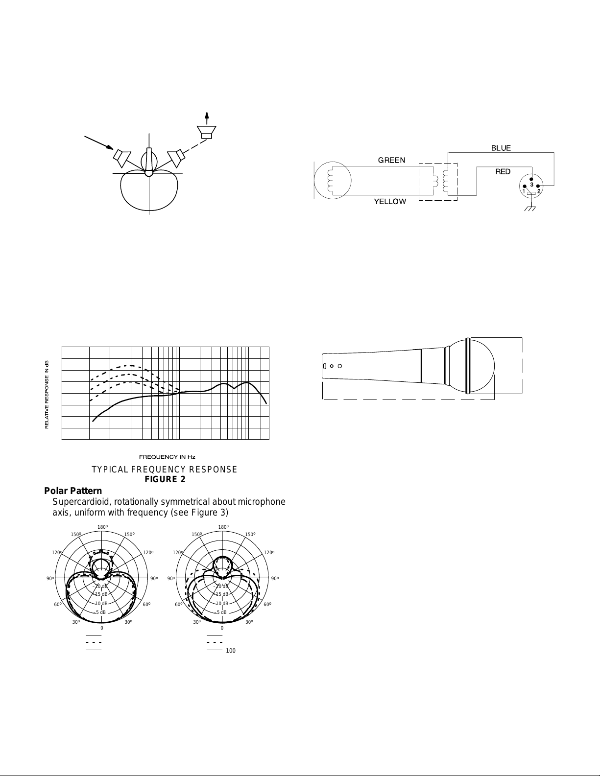
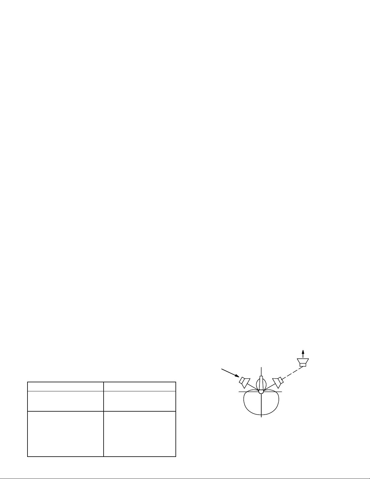
For maximum rejection of unwanted sound, place the
stage monitor(s) or P.A. system loudspeaker at a 60° angle
from the rear of the BETA 58A, not directly behind it. See
Figure 1. Always check out the stage setup before a performance to ensure that microphone and monitor placement is
optimum.
MONITOR
LOUDSPEAKER(S)
90°
180°
120°120°
0°
P.A. SYSTEM
LOUDSPEAKER
RECOMMENDED LOUDSPEAKER LOCATIONS
FIGURE 1
SPECIFICATIONS
Type
Dynamic (moving coil)
Frequency Response
50 to 16,000 Hz (see Figure 2)
NOTE: The curve below shows on-axis response at a
distance of 2 feet from a uniform sound source. Your
response may vary, depending on microphone position.
Output Level (at 1,000 Hz)
Open Circuit Voltage: –51.5 dBV/Pa* (2.6 mV)
*1 Pa = 94 dB SPL
Impedance
Rated impedance is 150 W (290 W actual) for connection
to microphone inputs rated low Z
Phasing
Positive pressure on diaphragm produces positive voltage
on pin 2 with respect to pin 3. See Figure 4.
INTERNAL WIRING
FIGURE 4
Case
Silver blue enamel-painted die cast metal with hardened,
matte-finished, spherical steel mesh grille
Adjustable, Stand Adapter
Slip-in microphone mounting, unbreakable, adjustable
through 180° with standard 5/8”-27 thread, black finish
Dimensions (See Figure 5)
+10
3 mm
(1/8 IN.)
25 mm
(1 IN.)
0
51 mm
(2 IN.)
–10
0.6 m
(2 FT)
500 1,000 2,000 5,000 10,000 20,00050 100 20020
TYPICAL FREQUENCY RESPONSE
FIGURE 2
Polar Pattern
Supercardioid, rotationally symmetrical about microphone
axis, uniform with frequency (see Figure 3)
o
180
o
150
o
120
o
90
o
60
–20 dB
–15 dB
–10 dB
–5 dB
o
30
250 Hz
500 Hz
1000 Hz
150
30
o
o
120
o
90
o
60
o
150
o
120
o
90
o
60
30
o
180
o
–20 dB
–15 dB
–10 dB
–5 dB
o
00
2500 Hz
6300 Hz
10000 Hz
150
30
o
o
TYPICAL POLAR PATTERNS
FIGURE 3
120
60
50 mm
(2 in.)
160 mm
(6.5 in.)
OVERALL DIMENSIONS
FIGURE 5
Net Weight
278 grams (9.92 oz)
Certification
Eligible to bear CE Marking. Conforms to European EMC
Directive 89/336/EEC. Meets applicable tests and performance criteria in European Standard EN55103 (1996)
parts 1 and 2, for residential (E1) and light industrial (E2)
environments.
o
FURNISHED ACCESSORIES
Adjustable Stand Adapter A25D. . . . . . . . . . . . . . . . . . . . . .
5/8” to 3/8” (Euro) Thread Adapter 95A2050. . . . . . . . . . . .
o
90
o
Storage Bag 26A21. . . . . . . . . . . . . . . . . . . . . . . . . . . . . . . . .
OPTIONAL ACCESSORIES
Windscreen A58WS Series (8 colors available). . . . . . . . . .
Isolation Mount A55M, A55HM. . . . . . . . . . . . . . . . . . . . . . .
7.6 m (25 ft.) Cable C25E, C25F. . . . . . . . . . . . . . . . . . . . . .
REPLACEMENT PARTS
Cartridge R176. . . . . . . . . . . . . . . . . . . . . . . . . . . . . . . . . . . . .
Grille Assembly RK265G. . . . . . . . . . . . . . . . . . . . . . . . . . . . .
Plug (Connector) Assembly 90F1984. . . . . . . . . . . . . . . . . .
2
Page 3
MODÈLE BETA 58A
R
MICROPHONE VOCAL DYNAMIQUE
SUPERCARDIOÏDE
GÉNÉRALITÉS
Le Shure BET A 58A est un microphone vocal dynamique
supercardioïde conçu pour la sonorisation professionnelle et
les enregistrements en studio. Il maintient une configuration
supercardioïde réelle dans toute sa gamme de fréquences.
Ceci assure un gain élevé avant Larsen, une isolation
maximum des autres sources sonores et un minimum de
coloration de tonalité hors axe. La courbe de réponse du
BETA 58A est idéale pour la prise de son vocale de près.
Grâce à sa construction robuste, sa monture antichoc
éprouvée et sa grille en acier trempé, il peut être malmené
sans que sa performance exceptionnelle soit affectée. La
sonorisation des chanteurs et choristes est l’une des
applications typiques du BETA 58A.
Avantages
S Gamme de fréquences adaptée à la voix avec médiums
extra/clairs et limiteur de basses
S Configuration cardioïde uniforme pour un gain élevé
avant Larsen et rejet supérieur des sons hors axe
S Aimant au néodymium pour un rapport signal/bruit élevé
S Grille en acier trempé résistante à l’usure et aux mauvais
traitements
S Système antichocs pneumatique avancé réduisant la
transmission des bruits mécaniques et des vibrations
S Faible sensibilité aux changements d’impédance de
charge
S Qualité et fiabilité légendaires de Shure.
APPLICATIONS ET PLACEMENT
Le BETA 58A est conçu pour la prise de son vocale de près
et peut être tenu à la main ou monté sur pied.
Quelques–unes des applications et techniques de
placement les plus courantes sont expliquées dans le
tableau ci–dessous. Ne pas oublier que la technique de
placement des micros est surtout une question de goût
personnel et qu’il n’y a pas de position ”correcte”.
PLACEMENT SUGGÉRÉ SONORITÉ
Lèvres à moins de 15 cm ou touchant le coupe–vent, dans l’axe du
micro.
15 à 60 cm de la bouche, juste
audessus de la base du nez.
20 à 60 cm de la bouche légèrment
hors axe.
90 cm à 1,8 m de distance.
Son robuste, basses accentuées, isolation maximum
d’autres sources sonores.
Sonorité naturelle, basses
réduites.
Sonorité naturelle, basses réduites, sifflements des ”s” minimum.
Petit son, distant, présence notable de bruits de fond.
RÈGLES GÉNÉRALES D’UTILISATION
DE MICROPHONES
1. Diriger le micro vers la source sonore, le plus loin possible des bruits indésirables. Les angles de captage des
microphones supercardioïdes tels que le BETA 58A étant
étroits, les bruits de l’arrière peuvent être captés et le positionnement peut ne pas être évident.
2. Placer le microphone aussi près que possible de la source sonore. Voir le tableau ci–dessus.
3. Plus la source sonore est proche du micro, plus les basses sont présentes.
4. N’utiliser qu’un microphone par source sonore.
5. La distance entre les microphones doit être d’au moins
trois fois celle de chaque micro à sa source sonore respective.
6. Utiliser le moins de microphones possible.
7. Placer les microphones aussi loin que possible des surfaces réfléchissantes.
8. Utiliser un coupe–vent si les microphones sont utilisés à
l’extérieur.
9. Éviter les manipulations inutiles pour minimiser le captage des bruits mécaniques et des vibrations.
10. Ne couvrir aucune partie de la grille avec la main.
EFFET DE PROXIMITÉ
Les microphones unidirectionnels tels que le BETA 58A
poussent progressivement les basses fréquences de 6 à 10
dB à 100 Hz lorsqu’ils sont placés à environ 6 mm de la
source sonore. Ce phénomène, connu sous le nom d’effet
de proximité peut être utilisé pour créer un son plus chaud et
plus puissant. Pour éviter les sons explosifs de basse
fréquence lorsque le microphone est utilisé de près, la
réponse de basses fréquences du BETA 58A est
progressivement atténuée. Ceci assure un meilleur contrôle
et permet à l’utilisateur de mieux tirer parti de l’effet de
proximité.
DISPOSITION DES RETOURS DE SCÈNE ET DES
HAUTS–PARLEURS DE SONORISATION
Pour un réjet maximal des sons indésirables, placer les
retours ou les haut–parleurs à 60_ par rapport au
microphone BETA 58A pas directement derrière (voir la
figure 1). Toujours examiner la mise en place de la scène
pour s’assurer que la disposition des microphones et
haut–parleurs est optimale.
RETOUR(S)
90°
PLACEMENT RECOMMANDÉ POUR LES
180°
120°120°
90°
0°
HAUT–PARLEURS
FIGURE 1
HAUT–PARLEURS DE
SONORISATION
3
Page 4
CARACTÉRISTIQUES
Á
Á
Á
Á
Á
Á
Á
Á
Á
Á
Á
Á
Type
Dynamique (bobine mobile)
Courbe de réponse
50 à 16 000 Hz (voir la figure 2)
Phase
Une pression positive sur le diaphragme produit une ten-
sion positive sur la broche 2 par rapport à la broche 3 (voir
la figure 4).
BLAU
VERT
ROUGE
+10
3 mm
25 mm
0
51 mm
–10
0.6 m
RÉPONSE RELATIVE EN DB
FRÉQUENCE HERTZIENNE
500 1,000 2,000 5,000 10,000 20,00050 100 20020
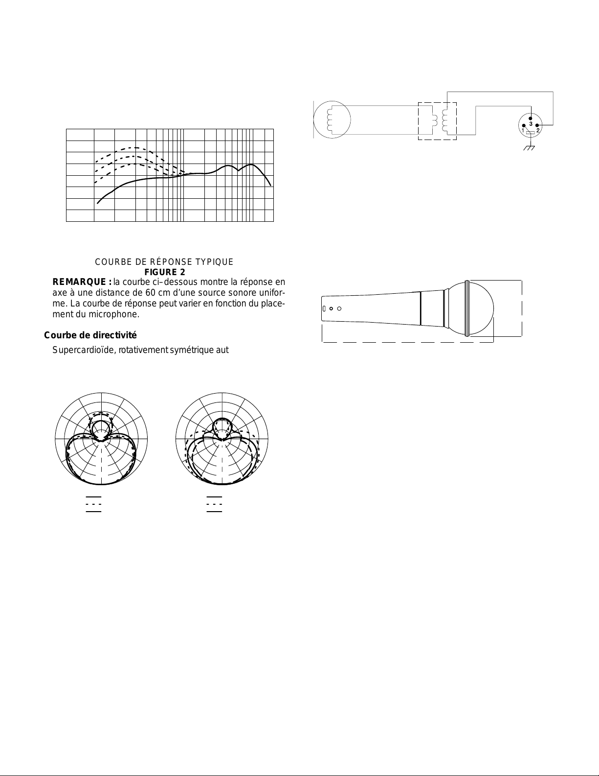
COURBE DE RÉPONSE TYPIQUE
FIGURE 2
REMARQUE : la courbe ci–dessous montre la réponse en
axe à une distance de 60 cm d’une source sonore uniforme. La courbe de réponse peut varier en fonction du placement du microphone.
Courbe de directivité
Supercardioïde, rotativement s ymétrique a utour d e l ’axe d u
microphone, constante avec la féquence (voir la figure 3)
o
180
o
150
o
120
o
90
o
60
–20 dB
–15 dB
–10 dB
–5 dB
o
30
250 Hz
500 Hz
1000 Hz
150
30
o
o
120
o
90
o
60
o
150
o
120
o
90
o
60
30
o
180
o
–20 dB
–15 dB
–10 dB
–5 dB
o
00
2500 Hz
6300 Hz
10000 Hz
150
30
o
o
COURBES DE DIRECTIVITÉ TYPIQUES
FIGURE 3
Niveau de sortie (à 1000 Hz)
Tension en circuit ouvert : –51,5 dBV* (2,6 mV)
*1 Pa = 94 dB SPL
Impédance
L’impédance nominale est de 150 W (290 W réelle) pour
connexion aux entrées de micros basse impédance.
120
60
JAUNE
CONNEXIONES INTERNES
FIGURE 4
Corps
Fonte émaillé bleu argenté avec grille sphérique matte en
acier trempé.
Adaptateur de pied réglable, verrouillable
À emboîtement, incassable, réglable à travers 180_ avec
filet standard de 5/8”–27. fini noir
Dimensions (Voir la figure 5)
50 mm
160 mm
DIMENSIONS HORS TOUT
FIGURE 5
Poids net
278 grammes
o
Homologations
Autorisé à porter la marque CE. Conforme à la directive
o
90
CEM européenne 89/336/CEE. Conforme aux critères
applicables de test et de performances de la norme
européenne EN 55103 (1996) parties 1 et 2 pour les
o
environnements résidentiels (E1) et d’industrie légère
(E2).
ACCESSOIRES FOURNIS
Adaptateur de pied réglable verrouillable A25D. . . . . . . . .
Adaptateur de filet 5/8 à 3/8 po. (Europe) 95A2050. . . . . .
Étui de rangement 26A21. . . . . . . . . . . . . . . . . . . . . . . . . . . .
ACCESSOIRES EN OPTION
Coupe vent Série A58WS (8 couleurs). . . . . . . . . . . . . . . . .
Monture isolante A55M, A55HM. . . . . . . . . . . . . . . . . . . . . .
Câble de 7,6 m C25E, C25F. . . . . . . . . . . . . . . . . . . . . . . . .
PIÈCES DE RECHANGE
Cartouche R176. . . . . . . . . . . . . . . . . . . . . . . . . . . . . . . . . . . .
Grille RK265G. . . . . . . . . . . . . . . . . . . . . . . . . . . . . . . . . . . . . .
Fiche (connecteur) 90F1984. . . . . . . . . . . . . . . . . . . . . . . . .
4
Page 5

MODELL BETA 58A
R
DYNAMISCHES SUPERNIEREN–TAUCHSPUL-
MIKROPHON FÜR SPRACHAUFNAHMEN
ALLGEMEINES
Beim Shure BETA 58A handelt e s si ch u m e in d ynamisches
Supernieren–Tauchspulmikrophon für Sprachaufnahmen mit
hoher Ausgangsleistung, das für professionelle Tonverstär-
kung und Tonstudioaufnahmen entwickelt wurde. Seine echte
Supernierencharakteristik erstreckt sich über den gesamten
Frequenzbereich. Dadurch werden hohe Verstärkung vor der
Rückkopplung, maximale Isolierung von anderen Schallquellen und minimal e a ußeraxiale Klangfärbung g ewährleistet. D as
BETA 5 8A w eist ein geformtes Frequenzverhalten auf, das für
Nahaufnahmen von Stimmen ideal ist. Aufgrund seiner robusten Konstruktion, des bewährten Schwingmetalldämpfer–Sy-
stems und des Gittergrills aus gehärtetem Stahl wird die über-
ragende Leistungsfähigkeit dieses Mikrophons durch grobe
Handhabung nicht beeinträchtigt. Zu den gebräuchlichsten
Einsatzbereichen des BETA 58A zählen seine Verwendung
durch Hauptsänger und Hintergrundsänger.
Merkmale
S Auf Sprachaufnahmen zugeschnittenes Frequenzverhal-
ten, mit aufgehelltem Mittenbereich und Baßdämpfung
S Gleichförmige Supernierencharakteristik für hohe Ver-
stärkung vor der Rückkopplung und überragende Unterdrückung außeraxialer Töne
S Neodym–Magnet für hohe S ignalrauschabstandsausgabe
S Gittergrill aus gehärtetem Stahl, widerstandsfähig gegen
Verschleiß und Mißbrauch
S Modernstes pneumatisch Schwingmetalldämpfer–Sy-
stem, dadurch nur minimale Übertragung von mechanischen Geräuschen und Vibrationen
S Geringe Empfindlichkeit gegen variable Abschlußimpe-
danz
S Bewährte Shure Qualität und Zuverlässigkeit
ANWENDUNG UND AUFSTELLUNG
Das BETA 58A ist für Nahaufnahmen von Stimmen vorge-
sehen und kann mit der Hand gehalten oder an einem Stativ
angebracht werden. Einige der gebräuchlichsten Anwen-
dungen und Aufstellungsverfahren sind in der nachfolgenden Tabelle aufgeführt. Beachten Sie bitte, daß der Mikro-
phoneinsatz weitgehend eine
„Geschmackssache“ ist – von
„richtigen“ oder „falschen“ Mikrophonpositionen kann hier
also nicht die Rede sein.
EMPFOHLENE
MIKROPHONAUF–STELLUNG
Weniger als 15 cm Abstand von
den Lippen oder Berührung des
Windschirms, axial zum Mikrophon.
15 bis 60 cm Abstand vom Mund,
etwas oberhalb der Nasenhöhe.
20 bis 60 cm Abstand vom Mund,
etwas zur Seite geneigt.
90 cm bis 1,8 m Abstand.
TONQUALITÄT
Robuster Klang, hervorgehobener Baß, maximale Isolierung
von anderen Quellen.
Natürlicher Klang, reduzierter
Baß.
Natürlicher Klang, reduzierter
Baß und minimale Zischlaute.
Dünnerer, entfernterer Klang;
merklicher Umgebungsgeräuschpegel.
ALLGEMEINE REGELN FÜR DEN MIKROPHONGEBRAUCH
1. Das Mikrophon auf die gewünschte Tonquelle und weg
von unerwünschten Quellen richten. Da Supernieren–
Mikrophone wie das BETA 58A eine enge Richtcharakteristik aufweisen und Töne aus dem Hintergrund aufgrei-
fen können, ist dies möglicherweise nicht offensichtlich.
2. Das Mikrophon so nahe wie möglich an die gewünschte
Tonquelle heranbringen. Siehe obige Tabelle.
3. Abstand verringern, wenn zusätzliches Baßverhalten gewünscht wird.
4. Je Tonquelle nur ein Mikrophon verwenden.
5. Der Abstand zwischen den Mikrophonen sollte mindestens drei m a l s o g r o ß sein wie deren Abstand zu den ein-
zelnen Quellen.
6. Die Anzahl der Mikrophone so gering wie möglich halten.
7. Mikrophone so weit wie möglich von Akustikflächen entfernt anbringen.
8. Einen Windschirm anbringen, wenn das Mikrophon im
Freien verwendet wird.
9. Mikrophone so wenig wie möglich anfassen, um die Auf-
nahme von mechanischen Geräuschen und Vibrationen
minimal zu halten.
10. Keinen Teil des Grills mit der Hand abdecken.
NAHEFFEKT
Unidirektionale Mikrophone wie das BETA 58A bewirken
eine progressive Verstärkung von Baßfrequenzen (um 6 bis
10 dB bei 100 Hz), wenn sich das Mikrophon in einem Abstand von 6 mm von der Tonquelle befindet (siehe Abbildung
2). Dieses als Naheffekt bezeichnete Phänomen kann zur
Erzeugung eines wärmeren, kräftigeren Tons verwendet
werden. Zur V erhinderung eines
„explosiven“ Tons niederer
Frequenz bei Nahaufnahmen wird das Baßverhalten des
BETA 58A allmählich gedämpft. Dies ermöglicht eine bessere Kontrolle und unterstützt den Benutzer beim Ausnützen
des Naheffekts.
5
Page 6

AUFSTELLUNG DER BÜHNENLAUTSPRECHER UND
LAUTSPRECHER FÜR BESCHALLUNGSANLAGEN
Zur maximalen Unterdrückung unerwünschter Töne den
bzw. die Bühnenlautsprecher oder den bzw. die Lautsprecher
der Beschallungsanlage in e inem W inkel v on 6 0_ zur Rücksei-
te des BET A 58A, nicht direkt dahinter aufstellen (siehe Abbildung 1). Vor einem Auftritt stets die Bühnenausstattung über-
prüfen, um sicherzustellen, daß die Aufstellung des
Mikrophons und der Bühnenlautsprecher optimal ist.
BÜHNENLAUTSPRECHER
90°
180°
LAUTSPRECHER DER
BESCHALLUNGSANLAGE
120°120°
Ausgangspegel (bei 1000 Hz)
Leerlaufspannung: –51,5 dBV/Pa* (2,6 mV)
*1 Pa = 94 dB SPL
Impedanz
Die Nennimpedanz für den Anschluß an niederohmige Mikrophoneingänge beträgt 150 W (Ist–Wert 290 W)
Phasenabgleich
Positiver Druck auf die Membran erzeugt positive Spannung an Stift 2 gegenüber Stift 3. Siehe Abbildung 4.
BLAU
GRÜN
ROT
GELB
0°
EMPFOHLENE LAUTSPRECHERSTELLUNGEN
ABBILDUNG 1
SPEZIFIKATIONEN
Typ
Dynamisch (Tauchspule)
Frequenzverhalten
50 bis 16.000 Hz (siehe Abbildung 2)
+10
3 mm
25 mm
0
51 mm
–10
0.6 m
RELATIVES VERHALTEN IN DB
500 1,000 2,000 5,000 10,000 20,00050 100 20020
FREQUENZ IN HZ
TYPISCHES FREQUENZVERHALTEN
ABBILDUNG 2
HINWEIS: Die Kurve unten zeigt ein axiales Verhalten in
einem Abstand von 0,6 m von einer gleichförmigen Ton-
quelle. Das Frequenzverhalten ist von der Mikrophonstel-
lung abhängig.
Polarcharakteristik
Supernierencharakteristik, rotationssymmetrisch um Mikro-
phonachse, gleichförmig mit Frequenz (siehe Abbildung 3)
o
180
o
150
o
120
o
90
o
60
–20 dB
–15 dB
–10 dB
–5 dB
o
30
250 Hz
500 Hz
1000 Hz
150
30
o
o
120
o
90
o
60
o
150
o
120
o
90
o
60
30
o
180
o
–20 dB
–15 dB
–10 dB
–5 dB
o
00
2500 Hz
6300 Hz
10000 Hz
150
30
o
o
TYPISCHE POLARCHARAKTERISTIK
ABBILDUNG 3
120
60
INTERNE SCHALTUNGEN
ABBILDUNG 4
Gehäuse
Silberblaues einbrennlackiertes Druckgußmetall mit gehärtetem, kugelförmigem Stahlgittergrill in matter Oberflächenausführung
Verstellbarer, einrastender Stativadapter
Gleitverbindung, bruchbeständig, durch 180_ verstellbar
mit 5/8”–27 Standardgewinde, schwarze Oberflächenausführung
Dimensions (siehe Abbildung 5)
50 mm
160 mm
GESAMTABMESSUNGEN
ABBILDUNG 5
Nettogewicht
278 Gramm
Zulassung
Zur CE–Kennzeichnung berechtigt. Entspricht der EU–
Richtlinie über elektromagnetische Verträglichkeit
89/336/EEC. Erfüllt die Prüfungs– und Leistungskriterien
der europäischen Norm EN 55103 (1996) Teil 1 und 2 für
Wohngebiete (E1) und Leichtindustriegebiete (E2).
MITGELIEFERTES ZUBEHÖR
o
Verstellbarer, einrastender Stativadapter A25D. . . . . . . . .
5/8 zu 3/8 Inch (Euro) Gewindeadapter 95A2050. . . . . . . .
Tasche 26A21. . . . . . . . . . . . . . . . . . . . . . . . . . . . . . . . . . . . . .
o
90
SONDERZUBEHÖR
o
Windschirm A58WS Serie (in 8 Farben erhältlich). . . . . . . .
Isolierbefestigung A55M, A55HM. . . . . . . . . . . . . . . . . . . . .
Kabel, 7,6 m C25E, C25F. . . . . . . . . . . . . . . . . . . . . . . . . . . .
ERSATZTEILE
Kapsel R176. . . . . . . . . . . . . . . . . . . . . . . . . . . . . . . . . . . . . . .
Grill–Baugruppe RK265G. . . . . . . . . . . . . . . . . . . . . . . . . . . .
Stecker– (Anschluß–) Baugruppe 90F1984. . . . . . . . . . . .
6
Page 7

MODELO BETA 58A
R
MICROFONO DINAMICO SUPERCARDIOIDE
PARA VOCALISTAS
GENERALIDADES
El Shure BETA 58A es un micrófono dinámico de
supercardioide para vocalistas con señal de salida de alta
intensidad diseñado para uso en refuerzo de sonido
profesional y en estudios de grabación. Mantiene un
verdadero patrón supercardioide en toda su gama de
frecuencias. Esto a segura u n a lto v alor d e g anancia a ntes d e
realimentación, aislamiento máximo d e o tras f uentes s onoras
y una coloración mínima d e l os t onos f uera d e s u e je p rincipal.
El BETA 58A tiene una respuesta de frecuencia cuya forma
es ideal para que un vocalista lo utilice de cerca. El
rendimiento superior de este micrófono n o s e v e a fectado p or
el trato duro debido a su resistente fabricación, su
comprobado sistema de montaje a prueba de choques y su
rejilla de malla de acero endurecido. Los usos típicos del
BETA 58A incluyen la captación de voces principales y de
fondo.
Características
S Respuesta de frecuencia diseñada para la voz humana
con aumento de frecuencias medias y atenuación progresiva de frecuencias bajas
S Patrón d e s upercardioide u niforme p ara l ograr u n a lto v alor
de ganancia a ntes d e realimentación y u n rechazo superior
de los sonidos fuera del eje principal de captación
S El imán de neodimio produce una salida con alta relación
de señal a ruido
S La rejilla de acero endurecido resiste el desgaste y abuso
S El sistema neumático de montaje contra choques reduce
al mínimo la transmisión de ruido mecánico y vibraciones
S Minimalmente afectado por las variaciones de la impe-
dancia de carga
S La legendaria calidad y confiabilidad de Shure
USOS Y COLOCACION
El BETA 58A está diseñado para captar voces a corta
distancia y puede sostenerse en la mano o en un pedestal.
Algunas de las técnicas más comunes de uso y colocación
se indican en la tabla siguiente. Recuerde que la técnica de
uso de los micrófonos es en gran parte cuestión de gusto
personal—no existe una posición de micrófono que sea la
”correcta”.
COLOCACION SUGERIDA DEL
MICROFONO
Los labios a no más de 15 cm de
la paravientos, en línea con el
eje de captación del micrófono.
De 15 a 60 cm de la boca, justo
arriba del nivel de la nariz.
De 20 a 60 cm de la boca,
ligeramente a un lado de ésta.
De 90 cm a 1,8 m de distancia.
CALIDAD DEL TONO
Sonido robusto, frecuencias
bajas enfatizadas, aislamiento
máximo de otras fuentes
sonoras.
Sonido natural, frecuencias
bajas reducidas.
Sonido natural, frecuencias
bajas reducidas y pocos
sonidos sibilantes.
Sonido más agudo y distante;
niveles perceptibles de sonido
ambiental.
REGLAS GENERALES DE USO DE MICROFONOS
1. Coloque el micrófono hacia la fuente sonora deseada y
alejado de las fuentes no deseadas. Debido a que los micrófonos supercardioide tales como el BET A 58A tienen
patrones de captación angostos y son capaces de captar
sonidos por su parte trasera, esto podría no ser obvio ni
evidente.
2. Coloque el micrófono lo más cerca posible a la fuente so-
nora deseada. Consulte la tabla arriba dada.
3. Acérquese al micrófono para obtener mayor respuesta
de frecuencias bajas.
4. Utilice sólo un micrófono para captar una fuente sonora.
5. La distancia entre un micrófono y otro deberá ser al menos tres veces la distancia de cada fuente a su micrófono.
6. Utilice el menor número d e m icrófonos que r esulte p ráctico.
7. Aleje los micrófonos lo más posible de las superficies reflectoras.
8. Instale una paravientos si se usa el micrófono a la intem-
perie.
9. Evite el manejo excesivo para reducir la captación de ruidos mecánicos y vibraciones.
10. No cubra parte alguna de la rejilla con la mano.
EFECTO DE PROXIMIDAD
Los micrófonos unidireccionales tales como el BET A 58A
introducen un aumento progresivo en las frecuencias bajas
de 6 a 10 dB a 100 Hz cuando el micrófono se coloca a aprox.
6 mm de la fuente sonora (vea la Figura 2). Este fenómeno,
conocido como el efecto de proximidad, puede usarse para
crear un sonido más cálido y fuerte. Para evitar sonidos de
baja frecuencia con intensidad explosiva al usar el
micrófono de cerca, el BETA 58A tiene una atenuación
progresiva en su respuesta de bajos. Esto ofrece mayor
control sobre el sonido y ayuda al usuario a aprovechar el
efecto de proximidad.
COLOCACION DE ALTOPARLANTES DE MONITOREO
Y DEL SISTEMA DE REPRODUCCION
Para el rechazo máximo del sonido no deseado, coloque
el o los altoparlantes de monitoreo o del sistema de
reproducción a un ángulo de 60_ respecto a la parte trasera
del micrófono BETA 58A; no los coloque directamente
detrás de éste (vea la Figura 1). Siempre compruebe la
disposición del escenario antes de una ejecución para
verificar que la colocación de micrófonos y altoparlantes es
la óptima.
ALTOPARLANTE(S) DE
MONITOREO
90°
COLOCACION RECOMENDADA DE ALTOPARLANTES
7
180°
120°120°
90°
0°
FIGURA 1
ALTOPARLANTE DEL
SISTEMA DE
REPRODUCCION
Page 8

ESPECIFICACIONES
Tipo
Dinámico (bobina móvil)
Respuesta de frecuencia
50 a 16.000 Hz (vea la Figura 2)
Fasaje
Una presión positiva en el diafragma del micrófono produce
un voltaje positivo en la clavija 2 con respecto a la clavija 3
(Vea la Figura 4).
AZUL
VERDE
ROJO
AMARILLO
+10
3 mm
25 mm
0
51 mm
–10
0.6 m
RESPUESTA RELATIVA EN DB
500 1,000 2,000 5,000 10,000 20,00050 100 20020
FRECUENCIA EN HZ
RESPUESTA DE FRECUENCIA TIPICA
FIGURA 2
NOTA: La curva abajo ilustrada muestra la respuesta de
una fuente sonora uniforme colocada en el eje de captación a una distancia de 0,6 m. La respuesta obtenida en
la práctica variará según la posición del micrófono.
Patrón polar
Supercardioide, simétrico respecto al eje del micrófono,
uniforme respecto a la frecuencia (vea la Figura 3)
o
180
o
150
o
120
o
90
o
60
–20 dB
–15 dB
–10 dB
–5 dB
o
30
250 Hz
500 Hz
1000 Hz
150
30
o
o
120
o
90
o
60
o
150
o
120
o
90
o
60
30
o
180
o
–20 dB
–15 dB
–10 dB
–5 dB
o
00
2500 Hz
6300 Hz
10000 Hz
150
30
o
o
PATRONES DE CAPTACION POLAR TIPICOS
FIGURA 3
Nivel de salida (a 1.000 Hz)
Voltaje en circuito abierto: –51,5 dBV/Pa* (2,6 mV)
*1 Pa = 94 dB SPL
120
60
CONEXIONES INTERNAS
FIGURA 4
Caja
Metal troquelado pintado de color plateado azul con rejilla
esférica de acero endurecido con acabado mate
Adaptador para pedestal ajustable
Ajustable a través de 180_ , irrompible, con rosca estándar
de 5/8”–27 y acabado en negro
Dimensiones (Vea la Figura 5)
50 mm
160 mm
DIMENSIONES TOTALES
FIGURA 5
Peso neto
278 g
o
Certificaciones
Califica para llevar las marcas CE. Cumple la directiva eu-
o
90
ropea 89/336/EEC de compatibilidad electromagnética.
Se ajusta a los criterios correspondientes de verificación
o
y funcionamiento establecidos en la norma europea EN
55103 (1996), partes 1 y 2, para zonas residenciales (E1)
y zonas de industria ligera (E2).
ACCESORIOS SUMINISTRADOS
Adaptador ajustable para pedesta A25D. . . . . . . . . . . . . . .
Adaptador de roscas de 5/8 a 3/8 pulg (Euro) 95A2050. .
Bolsa de almacenamiento 26A21. . . . . . . . . . . . . . . . . . . . .
ACCESORIOS OPCIONALES
Paravientos Serie A58WS (disponible en 8 colores). . . . .
Montaje con aislamiento A55M, A55HM. . . . . . . . . . . . . . .
Cable de 7,6 m C25E, C25F. . . . . . . . . . . . . . . . . . . . . . . . .
Impedancia
La impedancia n ominal e s d e 1 50 W ( real: 290 W) p ara c onexión a entradas de micrófono de baja impedancia (baja Z)
REPUESTOS
Cartucho R176. . . . . . . . . . . . . . . . . . . . . . . . . . . . . . . . . . . . .
Conjunto de rejilla RK265G. . . . . . . . . . . . . . . . . . . . . . . . . .
Conjunto de enchufe (conector) 90F1984. . . . . . . . . . . . . .
8
Page 9

MODELLO BETA 58A
R
MICROFONO VOCALE DINAMICO
A SUPERCARDIOIDE
INTRODUZIONE
Il modello BETA 58A della Shure è un microfono vocale
dinamico a supercardioide ad uscita elevata, realizzato per
applicazioni in studi di registrazione ed impianti di
amplificazione professionali. La caratteristica di ricezione a
supercardioide rimane invariata i n t utto i l c ampo d i f requenza
del microfono, assicurando così un elevato guadagno a
monte della retroazione, massimo isolamento acustico e
minima colorazione dei toni fuori asse. L’andamento della
risposta in frequenza del modello BETA 58A è ideale per
applicazioni vocali in cui il microfono venga tenuto
estremamente vicino alle labbra. Grazie alla sua costruzione
robusta, al s istema c omprovato d i m ontaggio a ntivibrazione e
alla griglia in acciaio temprato, un uso aggressivo del
microfono non influisce sulle sue eccellenti prestazioni.
Applicazioni tipiche d el m odello B ETA 5 8A i ncludono l ’uso s ia
da parte d i c antanti s olisti c he d el c o ro d i a ccompagnamento.
Caratteristiche
S Risposta in frequenza ottimizzata per applicazioni vocali,
con aumento della risposta ai toni intermedi e attenuazione a quelli bassi.
S Diagramma di ricezione a supercardioide uniforme, che
presenta un elevato guadagno a monte della retroazione
ed una reiezione superiore dei suoni fuori asse.
S Magnete al neodimio, per ottenere un elevato rapporto
segnale/rumore all’uscita.
S Griglia in acciaio temprato, resistente all’usura e agli
abusi.
S Avanzato sistema di montaggio antivibrazione pneumati-
co, che riduce al minimo la trasmissione di vibrazioni e
suoni di natura meccanica.
S Bassa sensibilità a variazioni dell’impedenza di carico.
S Le leggendarie qualità e affidabilità Shure.
APPLICAZIONI E COLLOCAZIONE
Il modello BETA 58A, realizzato p er a pplicazioni v ocali i n c ui
il microfono si trovi estremamente vicino alle labbra, può
essere tenuto in mano o montato su un supporto. La tabella
che segue riporta alcune delle più comuni applicazioni e
tecniche di collocazione. Ricordare sempre che le tecniche
microfoniche dipendono l argamente d alle p referenze p ersonali
e che non esiste un’unica posizione ”giusta” del microfono.
REGOLE GENERALI PER L’USO DEL MICROFONO
1. Rivolgere il microfono v erso la s orgente s onora desiderata
e lontano da sorgenti indesiderate. Dato che i m icrofoni a
supercardioide, come il modello BETA 58A, presentano
diagrammi di ricezione stretti ed in grado di rilevare suoni
provenienti dal retro, ciò può non essere o vvio n é intuitivo.
2. Collocare il microfono quanto più vicino possibile alla sor gente sonora desiderata. Consultare la tabella precedente.
3. Per ottenere una maggiore risposta ai toni bassi, tenere
il microfono vicino alle labbra.
4. Usare solo un microfono per ciascuna sorgente sonora
da ricevere.
5. Mantenere la distanza tra più microfoni ad un valore
uguale ad almeno tre volte la distanza tra ciascuna sorgente sonora ed il corrispondente microfono.
6. Usare il numero minimo di microfoni consentito dall’applicazione.
7. Collocare i microfoni quanto più lontano possibile da su-
perfici riflettenti.
8. Quando si usa un microfono all’aperto, utilizzare uno
schermo paravento.
9. Evitare movimenti eccessivi d e l m icrofono, p er r idurre a l m inimo la ricezione di vibrazioni e s uoni d i n atura meccanica.
10. Non coprire nessuna parte della griglia con la mano.
EFFETTO DI PROSSIMITÀ
Nei microfoni unidirezionali, come il modello BETA 58A, la
risposta alle basse frequenze aumenta progressivamente
da 6 a 10 dB a 100 Hz quando il microfono si trova ad una
distanza di circa 6 mm dalla sorgente sonora. Questo
fenomeno, noto come effetto di prossimità, può essere
utilizzato per creare un suono più potente e caldo. Per
evitare suoni esplosivi a basse frequenze durante l’uso
ravvicinato, la risposta del microfono ai toni bassi si attenua
gradualmente. Ciò consente un controllo maggiore ed è di
ausilio nello sfruttare l’effetto di prossimità.
COLLOCAZIONE DEGLI ALTOPARLANTI PER LA
DIFFUSIONE SONORA AL PUBBLICO E DI
CONTROLLO DEL PALCOSCENICO
Per ottenere la massima reiezione dei suoni indesiderati,
collocare gli altoparlanti di controllo del palcoscenico o quelli
dell’impianto per il pubblico ad un angolo di 60_ rispetto
all’asse posteriore del microfono, non direttamente dietro di
esso (vedi Figura 1). Prima della rappresentazione,
controllare sempre l’allestimento del palcoscenico per
verificare la collocazione ottimale del microfono e degli
altoparlanti di controllo.
COLLOCAZIONE SUGGERITA
DEL MICROFONO
Labbra a meno di 15 cm dal microfono o a contatto con lo schermo paravento, lungo l’asse del microfono.
Distanza dalle labbra compresa tra
15 e 60 cm, appena sopra l’altezza
del naso.
20 e 60 cm, leggermente fuori asse
sull’uno o l’altro lato.
Distanza compresa t ra 9 0 c m e 1 ,8 m .
QUALITÀ DEI TONI
Suono robusto, enfasi dei toni
bassi, massimo isolamento da
altre sorgenti.
Suono naturale, toni bassi
ridotti.
Suono naturale, toni bassi
ridotti e suoni sibilanti ridotti al
minimo.
Suono lontano e affievolito;
livelli evidenti di rumore ambientale.
ALTOPARLANTI DI
CONTROLLO
180°
120°120°
90°
0°
90°
COLLOCAZIONE SUGGERITA DEGLI ALTOPARLANTI
FIGURA 1
9
ALTOPARLANTE
DELL’IMPIANTO
DI
DIFFUSIONE SONORA
AL PUBBLICO
Page 10

DATI TECNICI
Tipo
Dinamico (bobina mobile)
Risposta in frequenza
Da 50 a 16.000 Hz (vedi Figura 2).
+10
3 mm
25 mm
0
51 mm
–10
0.6 m
RISPOSTA RELATIVA, DB
500 1,000 2,000 5,000 10,000 20,00050 100 20020
FREQUENZA, HZ
TIPICA RISPOSTA IN FREQUENZA
FIGURA 2
NOTA: il grafico che segue mostra la risposta lungo l’asse
ad una distanza di 60 cm da una sorgente sonora uniforme. In una specifica applicazione la risposta può variare,
a seconda della posizione del microfono.
Relazione di fase
Una pressione positiva sul diaframma produce una tensio-
ne positiva al piedino 2 rispetto al piedino 3 (vedi Figura 4).
BLU
VERDE
ROSSO
GIALLO
COLLEGIAMENTI INTERNI
FIGURA 4
Contenitore
Corpo in metallo pressofuso con smaltatura blu–argento
e griglia sferica in acciaio temprato con finitura opaca.
Adattatore regolabile per supporto
A innesto, senza slittamento, infrangibile, regolabile per
180_ con filettatura standard 5/8”–27, finitura nera
Dimensioni (vedi Figura 5)
50 mm
Diagramma polare
A supercardioide con simmetria rotazionale rispetto all’as-
se del m icrofono, u niforme c on l a f requenza ( vedi F igura 3 )
o
180
o
150
o
120
o
90
o
60
.
–20 dB
–15 dB
–10 dB
–5 dB
o
30
250 Hz
500 Hz
1000 Hz
150
30
o
o
120
o
90
o
60
o
150
o
120
o
90
o
60
30
TIPICI DIAGRAMMI POLARI
o
180
o
–20 dB
–15 dB
–10 dB
–5 dB
o
00
2500 Hz
6300 Hz
10000 Hz
150
30
o
o
FIGURA 3
Livelli di uscita (a 1.000 Hz)
Tensione a circuito aperto: –51,5 dBV/Pa* (2,6 mV)
*1 Pa = 94 dB SPL
Impedenza
Valore nominale: 150 W (290 W effettivi) per il collegamento a ingressi microfonici con bassi valori nominali di impedenza.
120
60
160 mm
DIMENSIONI TOTALI
FIGURA 5
Peso netto
o
278 g
CERTIFICAZIONI
o
90
o
Contrassegnabile con il marchio CE. Conforme alla diretti-
va europea sulla compatibilità elettromagnetica
89/336/CEE. Conforme ai criteri sulle prestazioni e alle
prove pertinenti specificati nella norma europea EN 55103
(1996) parti 1 e 2, per ambienti residenziali (E1) e indu-
striali leggeri (E2).
ACCESSORI IN DOTAZIONE
Adattatore regolabile per supporto A25D. . . . . . . . . . . . . . .
Adattatore per filettatura (Euro) da 5/8 a 3/8 di poll. 95A2050.
Fodero 26A21. . . . . . . . . . . . . . . . . . . . . . . . . . . . . . . . . . . . . .
OPTIONAL
Schermo paravento serie A58WS (in 8 diversi colori). . . . .
Montatura per isolamento A55M, A55HM. . . . . . . . . . . . . .
Cavo, 7,6 m C25E, C25F. . . . . . . . . . . . . . . . . . . . . . . . . . . .
RICAMBI
Cartuccia R176. . . . . . . . . . . . . . . . . . . . . . . . . . . . . . . . . . . . .
Gruppo griglia RK265G. . . . . . . . . . . . . . . . . . . . . . . . . . . . . .
Gruppo spina (connettore) 90F1984. . . . . . . . . . . . . . . . . . .
10
Page 11

SHURE Incorporated Web Address: http://www.shure.com
222 Hartrey Avenue, Evanston, IL 60202–3696, U.S.A.
Phone: 847-866–2200 Fax: 847-866-2279
In Europe, Phone: 49-7131-72140 Fax: 49-7131-721414
In Asia, Phone: 852-2893-4290 Fax: 852-2893-4055
Elsewhere, Phone: 847-866–2200 Fax: 847-866-2585
 Loading...