

Page 1
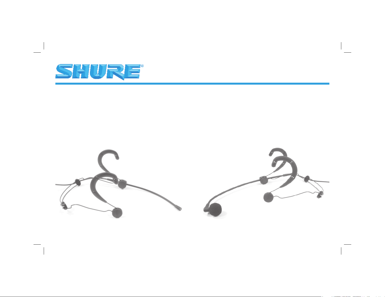
Subminiature Condenser Headworn Microphones
Models BETA 53™, BETA 54™ User Guide
BETA 54BETA 53
Page 2

English: page 1
Français: page 11
Deutsch: Seite 21
Español: Página 31
Italiano: Pagina 41
Page 3

Introduction
Shure models BETA 53™ and BETA 54™ are subminiature, electret condenser head worn microphones. They provide
uncompromised sound quality and reliability with minimal visibility in applications such as broadcast, theater, and
touring. Despite their small size, each microphone’s condenser element delivers full, clear, and natural reproduction of
speech and vocals. The microphone features a durable, low-profi le wire frame headband which is fully adjustable for
stability and comfort. A plastic carrying case protects the microphone and its accessories.
BETA 53 Features
• Omnidirectional polar pattern for minimal handling noise and fl exible microphone placement
• Extended, fl at frequency response provides accurate speech and vocal reproduction
• Two interchangeable protective caps for response shaping
• Foam windscreens minimize breath noise and “popping”
• Available with an in-line preamp or with a TA4F connector for wireless applications
• Choice of black or tan fi nish to suit your performance environment
BETA 54 Features
• Supercardioid polar pattern provides maximum gain-before-feedback and ambient rejection
• Extended frequency response tailored for vocal performances
• Able to handle extremely high sound pressure levels (SPL)
• Snap-fi t foam windscreens stay in place during intensive movement
• Available with an in-line preamp or with a TA4F connector for wireless applications
• Choice of black or tan fi nish to suit your performance environment
1
English
Page 4
2
English
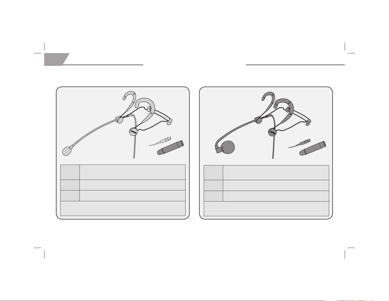
BETA 53 MODELS
• Omnidirectional
• For broadcast and stage
Available Models
BETA 54 MODELS
• Supercardioid
• For stage and vocal performance
WBH53B
WBH53T
BETA 53
BETA 53 • Black fi nish
• Detachable in-line preamp for wired applications
• Requires phantom power
WBH53B • Black fi nish
• TA4F connector for wireless applications
WBH53T • Tan fi nish
• TA4F connector for wireless applications
All models include: microphone and headband (1 each), foam windscreens (2), standard
protective cap (2), fi ltered protective cap (2), swiveling lapel clip (1), boom holder (2),
logo pad (1) and plastic carrying case (1).
WBH54B
WBH54T
BETA 54
BETA 54 • Black fi nish
• Detachable in-line preamp for wired applications
• Requires phantom power
WBH54B • Black fi nish
• TA4F connector for wireless applications
WBH54T • Tan fi nish
• TA4F connector for wireless applications
All models include: microphone and headband (1 each), snap-fi t foam windscreens (2),
standard protective cap (2), swiveling lapel clip (1), boom holder (2), logo pad (1) and
plastic carrying case (1).
Page 5
1
2
3
4
5
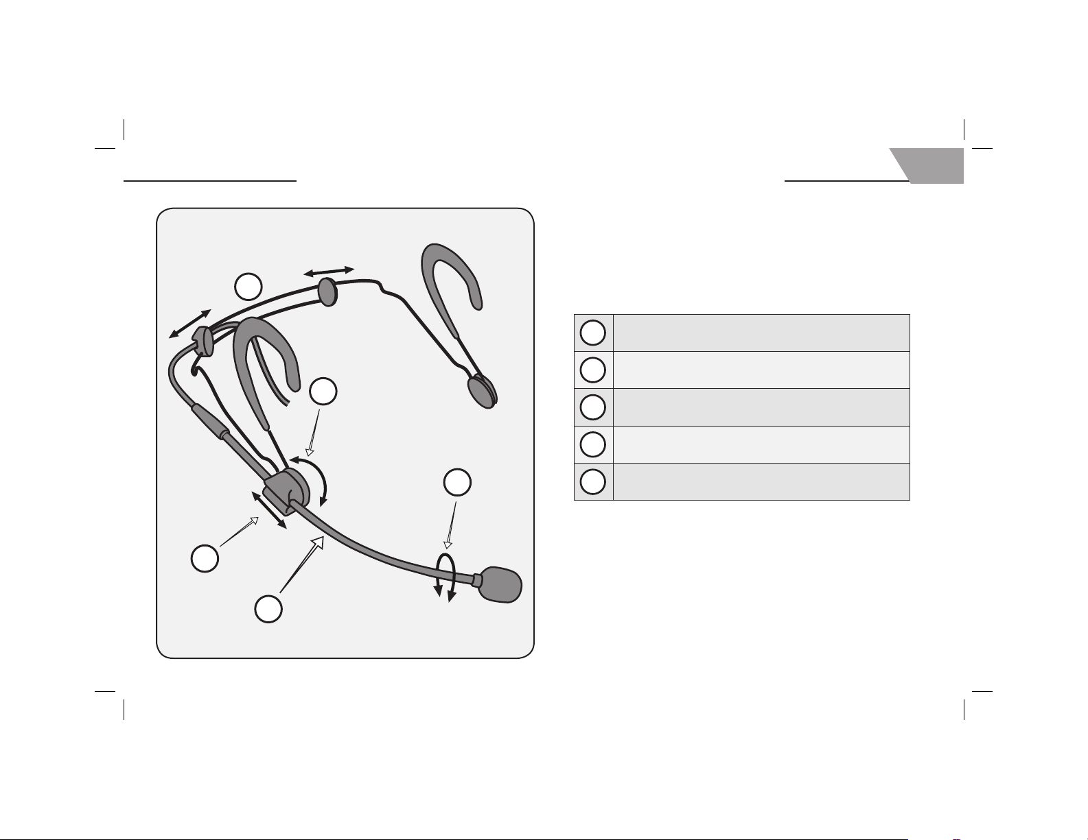
Adjusting the Headband and Microphone
Adjust headband width
1
Adjust boom height
2
Adjust boom length
3
Do not attempt to bend the microphone boom!
4
3
English
“Roll” the boom for subtle adjustments of microphone position
5
Page 6

4
Using the Windscreens and Protective Caps
BETA 54
English
• Foam windscreens may be cleaned with soap and water.
• For the best sound quality, replace damaged or clogged
protective caps and windscreens.
BETA 53
Standard protective cap
• Gold mesh
• No attenuation
Filtered protective cap
• Silver mesh
• Attenuates high frequencies
(see page 52)
Grip the internal frame of the windscreen fi rmly when connecting or
removing. Do not pull on the foam itself.
• To connect, push the windscreen until it snaps into place over the
cartridge.
• To remove, pull the windscreen directly off of the cartridge.
Always use the BETA 54 with the
standard protective cap only.
Using the microphone with no
cap, or with the fi ltered cap, will
degrade sound quality and alter
the microphone’s polar pattern.
Page 7

Wearing the BETA 53 and BETA 54
5
English
Page 8

6
13 mm
(.5 in.)
13 mm
(.5 in.)
English
Positioning the Microphone
BETA 53 BETA 54
• Position the omnidirectional BETA 53 microphone
near the corner of the mouth
• If necessary, roll the boom to avoid contact with
skin and facial hair
• Point the unidirectional BETA 54 microphone at
the corner of the mouth
Page 9

1
2
3
4
5
Wearing the Microphone on Either Side
All models may be worn with the microphone on the left or the right.
7
English
• Carefully detach the boom holder (1), logo pad (2), and
microphone cable (3) from the headband.
• Reattach the boom holder to the opposite side of the wire frame (4).
• Reattach the logo pad (5) and microphone cable (6).
6
Page 10

8
English
Component Black Tan
Foam Windscreen (5 pieces) RPM304 RPM306
1
Standard Protective Cap (gold mesh) (5 pieces)
2
Filtered Protective Cap* (silver mesh) (5 pieces)
Microphone/Boom Assembly with TA4F Con-
3
nector (1 piece)
Swiveling Lapel Clip (5 pieces) RPM510 RPM512
4
Boom Holder and Logo Pad (2 each) RPM570 RPM580
5
Headband (1 piece, with boom holder and
6
logo pad)
4-Pin Mini Connector (TA4F) (1 piece) WA331**
7
In-Line Preamp (1 piece) RPM626**
8
Not
Battery Powered Preamp (1 piece) MX1BP**
Pictured
Not
Phantom Power Supply (1 piece) PS1A**
Pictured
*See the frequency response curve on page 52
**Available in black only
BETA 53 Replacement Parts and Accessories
RPM208 RPM212
RPM220 RPM214
RPM132 RPM134
1
RPM550 RPM560
3
2
4
6
5
7
8
Page 11

5
3
2
4
7
BETA 54 Replacement Parts and Accessories
Component Black Tan
Microphone/Boom Assembly with TA4F Con-
1
nector (1 piece)
Standard Protective Cap (gold mesh) (5 pieces)
2
Snap-fi t Foam Windscreen (4 pieces) RPM316 RPM318
3
Swiveling Lapel Clip (5 pieces) RPM510 RPM512
4
Boom Holder and Logo Pad (2 each) RPM570 RPM580
5
Headband (1 piece, with boom holder and
6
logo pad)
4-Pin Mini Connector (TA4F) (1 piece) WA331*
7
In-Line Preamp (1 piece) RPM626*
8
Not
Battery Powered Preamp (1 piece) MX1BP*
Pictured
Not
Phantom Power Supply (1 piece) PS1A*
Pictured
*Available in black only
RPM646 RPM648
RPM208 RPM212
RPM550 RPM560
9
English
1
6
8
Page 12

10
English
Specifications
BETA 53 BETA 54
Specifi cation Wired Wireless Wired Wireless
Type Condenser (electret bias) Condenser (electret bias)
Frequency Response 20Hz to 20KHz (see page 52) 50Hz to 20KHz (see page 52)
Polar Pattern Omnidirectional (see page 52) Supercardioid (see page 52)
Output Noise (equivalent
dBSPL, A-weighted)
Signal-to-Noise Ratio 55 dB at 94 dB SPL 55.0 dB at 94 dBSPL
Recommended Minimum Input
Impedance
Preamp Output Impedance 136Ω 136Ω
Output Level, open circuit, ref.
1v/Pa at 1 kHz
Maximum Sound Pressure
Level
Dynamic Range 108 dB (max. SPL with 1k load, minus
Current Drain 4.6 mA (preamp and microphone) 60-130 μA (microphone only) 4.6 mA (preamp and microphone) 60-130 μA (microphone only)
Output Polarity
Positive pressure on the
diaphragm produces a positive
voltage at:
Power Requirements
Net Weight 135.35 g (4.75 oz.)
Cable 1.5 m (5 ft.), small-diameter, shielded, with mini 4-pin connector (TA4F)
39.0 dB typical; 42.0 dB maximum 39.0 dB typical; 42.0 dB maximum
>1 kΩ 20 kΩ >1 kΩ 20 kΩ
-50.0 ± 3.0dB
3.16mV
147 dBSPL at 1% THD/1 kΩ load 142 dBSPL at 1% THD/20 kΩ load 149 dBSPL at 1% THD/1 kΩ load 144 dBSPL at 1% THD/20 kΩ load
typical A-wt. noise)
Pin 2 relative to pin 3 at the output
connector of the preamp
Phantom power; 11 to 52 Vdc positive
on pins 2 and 3, return on pin 1 (ground)
microphone and in-line preamp
-54.0 ± 3.0dB
2.0mV
103 dB (max. SPL with 20k load,
minus typical A-wt. noise)
Pin 3 (black lead) relative to pin 1
(shield lead) at the output connector
of the microphone
+5 Vdc on pin 2, return on pin 1 (ground) Phantom power; 11 to 52 Vdc positive
35.35 g (1.25 oz.)
microphone only
-52.0 ± 3.0dB
2.51mV
110 dB (max. SPL with 1k load, minus
typical A-wt. noise)
Pin 2 relative to pin 3 at the output
connector of the preamp
on pins 2 and 3, return on pin 1 (ground)
135.35 g (4.75 oz.)
microphone and in-line preamp
-56.0 ± 3.0dB
1.58mV
105 dB (max. SPL with 20k load,
minus typical A-wt. noise)
Pin 3 (black lead) relative to pin 1
(shield lead) at the output connector
of the microphone
+5 Vdc on pin 2, return on pin 1 (ground)
35.35 g (1.25 oz.)
microphone only
Page 13

Polar Patterns and Frequency Response
20 200001000 1000050 100
9876543298765432
+10
0
–10
Hz
dB
–20
+20
20 200001000 1000050 100
9876543298765432
+10
0
–10
Hz
dB
15 mm (.6 in)
606mm(2ft)
+20
–20
–30
0º
125º
BETA 53 BETA 54
51
1
Capuchon standard
2
Capuchon à fi ltre
–20 dB
–15 dB
–10 dB
–5 dB
250 Hz
500 Hz
1000 Hz
Standard Cap
Filtered Cap
1
2
2
Standardmäßige Kappe
Gefi lterte Kappe
–20 dB
–15 dB
–10 dB
–5 dB
2.5 kHz
6.3 kHz
10 kHz
1
1
Tapa estándar
2
Tapa con fi ltro
1
Cappuccio standard
2
Cappuccio dotato di fi ltro
–20 dB
–15 dB
–10 dB
–5 dB
250 Hz
500 Hz
1000 Hz
–20 dB
–15 dB
–10 dB
–5 dB
2.5 kHz
6.3 kHz
10 kHz
Page 14

52
2SK1109
Wiring and Certification
Shield (ground)
Red1 (+5Vdc)
Black (audio out)
3
2
3
1
4
2
20k
1.0 uf
3
1
4
2
+
+5Vdc
100k
–
1. Rouge
2. Noir (sortie audio)
3. Blindage (masse)
4. Corps (masse)
5. Capsule de microphone
6. Circuit d’essai sans fi l
Eligible to bear CE marking. Conforms
to European EMC directive 89/336/EEC.
Meets applicable tests and performance
criteria in European EMC Standard EN
55103 (1996) parts 1 and 2, for residential
(E1) and light industrial (E2) environments.
Meets applicable test and performance
criteria in European wireless microphone
EMC standard EN 301 489 Parts 1 and 9.
Case (ground)
Microphone Cartridge
Autorisé à porter la marque CE. Conforme
à la directive CEM européenne 89/336/
CEE. Conforme aux critères applicables
de test et de performances de la norme
CEM européenne EN 55103 (1996)
parties 1 et 2 pour les environnements
résidentiels (E1) et d’industrie légère (E2).
Conforme aux critères applicables de test
et de performances de la norme CEM
européenne EN 301 489 Parties 1 et 9.
4
5
1. Rot
2. Schwarz (Audioausgang)
3. Abschirmung (Masse)
4. Gehäuse (Masse)
5. Mikrofonkapsel
6. Prüfkreis des Drahtlossystems
1. Rojo
2. Negro (salida de audio)
3. Blindaje (tierra)
4. Chasis (tierra)
5. Cápsula de micrófono
6. Circuito de prueba de sistema inalámbrico
Zur CE-Kennzeichnung berechtigt.
Entspricht der EU-Richtlinie über
elektromagnetische Verträglichkeit
89/336/EWG. Erfüllt die Prüfungs- und
Leistungskriterien der europäischen Norm
EN 55103 (1996) für elektromagnetische
Verträglichkeit, Teil 1 und 2, für
Wohngebiete (E1) und Gewerbegebiete
(E2). Erfüllt die Prüfungs- und
Leistungskriterien der europäischen Norm
EN 301 489 Teil 1 und 9.
Wireless Test Circuit
Califi ca para portar la marca CE. Cumple
la directiva europea 89/336/EEC de
compatibilidad electromagnética. Se
ajusta a los criterios correspondientes de
verifi cación y funcionamiento establecidos
en la norma europea de compatibilidad
electromagnética EN 55103 (1996), partes
1 y 2, para zonas residenciales (E1) y zonas
de industria ligera (E2). Se ajusta a los
criterios correspondientes de verifi cación y
funcionamiento establecidos en la norma
europea de compatibilidad electromagnética
EN 301 489 Partes 1 y 9.
6
1. Rosso
2. Nero (uscita audio)
3. Schermatura (massa)
4. Involucro (massa)
5. Capsula
6. Circuito per test wireless
Contrassegnabile con il marchio CE.
Conforme alla direttiva 89/336/CEE
della Comunità Europea, relativa alla
compatibilità elettromagnetica. Soddisfa i
criteri di prestazione e le verifi che pertinenti
nella regolamentazione europea sulla
compatibilità elettromagnetica a norma
EN 55103 (1996) parti 1 e 2, relativa ad
ambienti domestici (E1) ed industriali leggeri
(E2). Soddisfa i criteri di prestazione e le
verifi che pertinenti nella regolamentazione
europea sulla compatibilità elettromagnetica
a norma EN 301 489 Parti 1 e 9.
Page 15

Patent Notice: Patent Des. 451,902
©2005 Shure Incorporated
27F3115 (Rev. 6)
SHURE Incorporated http://www.shure.com
United States, Canada, Latin America, Caribbean:
5800 W. Touhy Avenue, Niles, IL 60714-4608, U.S.A.
Phone: 847-600-2000 U.S. Fax: 847-600-1212 Int’l Fax: 847-600-6446
Europe, Middle East, Africa:
Shure Europe GmbH, Phone: 49-7131-72140 Fax: 49-7131-721414
Asia, Pacific:
Shure Asia Limited, Phone: 852-2893-4290 Fax: 852-2893-4055
 Loading...