

Shure AXT630, AXT631, AXT632 User Manual
General Description
power
SET
2 3
1
AXT631
606-814 MHz
Antenna Distribution
antenna
in
B A
4
5 6
8
7 9
10
11
12
14
13
AXT631
4B 3B 2B 1B
RF outputs
4A 3A 2A 1A
RF outputs
PoE Class 1
Antenna Distribution Systems send the RF signal from a single pair of antennas to multiple receivers. Ultra-linear amplification and adjustable attenuation
optimize performance in difficult RF environments. Selectable input filters
match the available frequency bands of transmitters, providing extra protection
from strong out-of-band signals. BNC antenna output pairs distribute bandfiltered signals to up to 4 receivers. A pair of wideband cascade ports supply
wideband RF signals to Spectrum Managers or additional antenna distribution
amplifiers. Networking allows Wireless Workbench to control filtering ranges
and attenuation. For added flexibility, Axient Antenna Distribution Systems
are compatible with Shure ULX-D and UHF-R receivers.
To maximize use of the RF spectrum, Antenna Distribution Systems are
available in the following frequency ranges:
• AXT630 (470-698 MHz)
• AXT631 (606-814 MHz)
• AXT632 (470-510 MHz and 630-787 MHz)
AXT630
Antenna Distribution System
Note: Instructions in this system guide apply all models of Axient Antenna
Distributions Systems.
Features
• Selectable input filtering provides system-wide protection against strong
out-of-band signals
• Wideband filtering option covers multiple bands
• Up to 15 dB of selectable RF attenuation for signal-to-noise optimization
• Front panel interface and Wireless Workbench 6 software control provide
easy setup and control of filtering, antenna power, and attenuation
• BNC outputs: 4 antenna output pairs
• Wideband RF cascade port with selectable 3 dB make-up gain for connecting wideband devices
• Ethernet Networking: 2 PoE enabled Ethernet ports
• IEC power ports enable daisy-chaining of AC power
Mounting Instructions
This component is designed to fit into an audio rack.
WARNING: To prevent injury this apparatus must be securely attached to
the rack.
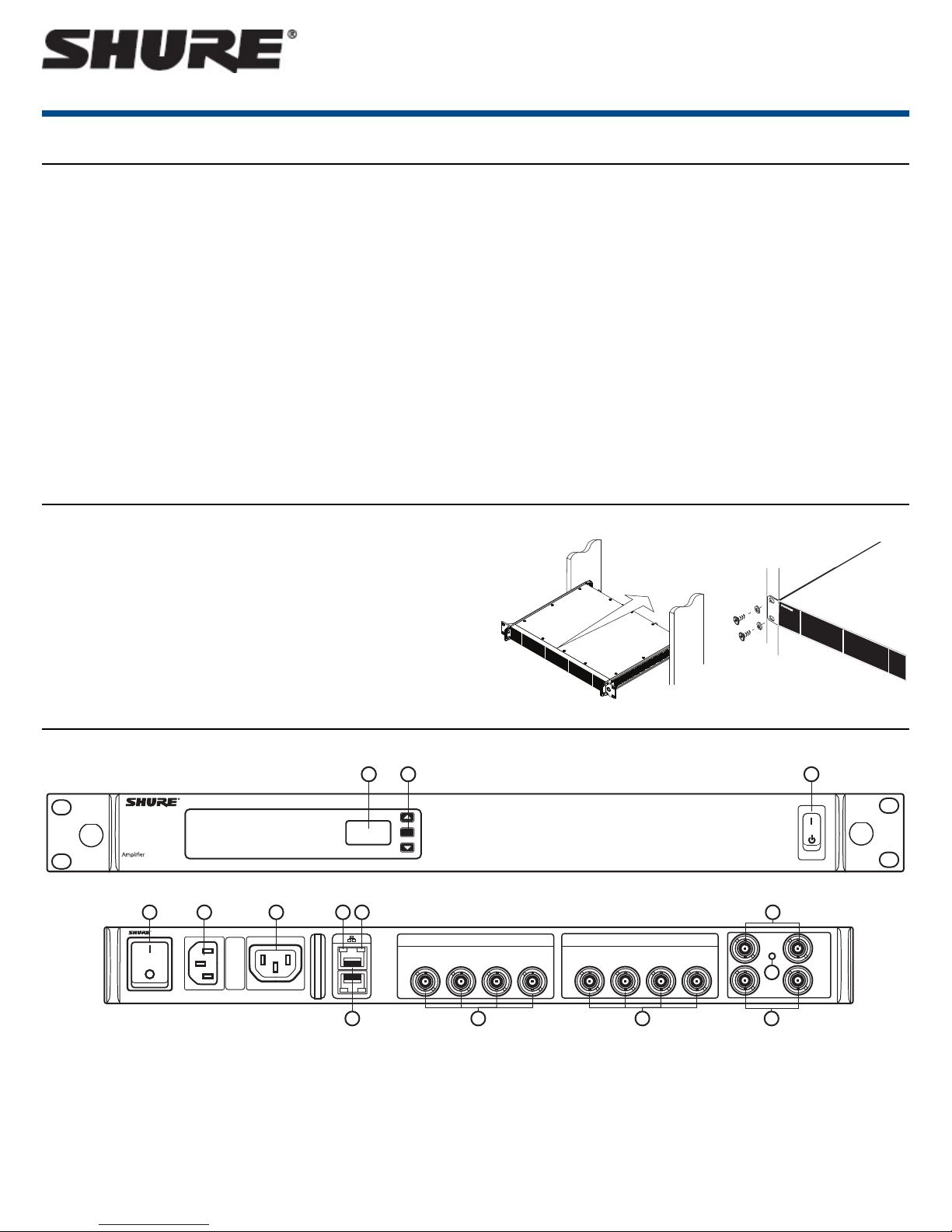
Controls and Connectors
① LCD Display
Displays menu and settings.
② Navigation Buttons
• Arrows: Scroll menus and change settings
• Set: Enables menu edits and saves changes
Tip: Press and hold the Set button for 1 second to activate the Hardware Identify feature in Wireless Workbench.
1/9©2017 Shure Incorporated

③ Power Switch
4B 3B 2B 1B
RF outputs
4A 3A 2A 1A
RF outputs
Powers the unit on or off
④ AC Power Primary Switch
AC Main Power Switch
⑤ AC Power In
IEC Connector, 100-240 V AC
⑥ AC Power Cascade
Use the IEC extension cables to connect up to 5 devices to a single AC power source.
⑦ Network Speed LED (amber):
• Off = 10 Mbps
• On = 100 Mbps
⑧ Ethernet Ports (2)
PoE Class 1 enabled. Connect to an Ethernet network to enable remote control and monitoring
⑨ Network status LED (green)
• Off = no network link
• On = network link active
• Flashing = network link active, flash rate corresponds to traffic volume
Shure IncorporatedAXT630 Antenna Distribution System
⑩ RF Output Connectors, Channel B
Distributes RF signal for Channel B
⑪ RF Output Connectors, Channel A
Distributes RF signal for Channel A
⑫ Antenna IN Ports, Channels A and B
Antenna inputs are DC biased for use with active antennas or in-line amplifiers.
⑬ RF Cascade Ports, Channels A and B
Passes the wideband RF signal from one device to the next, allowing up to 5 devices to share a single pair of antennas.
⑭ Antenna Input Status LED
• Green = DC power on
• Off = DC power off
• Red = Antenna fault or over-current condition
Antennas
The Antenna Distribution Systems are compatible with front-mounted antennas or with remote-mounted antennas.
Note: When using the input band filtering function, select an antenna with
bandwidth to cover the filter range.
Installing Front-mounted Antennas
Mounting the antennas on the front panel improves system performance by
providing a clear signal path for the RF signal. Use the supplied bulkhead
adapter kit to install the antennas on the front panel.
1. Insert the bulkhead adapters on the supplied front-mounting cables
through the holes in each bracket and secure them from the front using
the supplied hardware.
2. Connect the supplied antennas cables to the antenna input BNC connectors.
3. Install the antenna onto the bulkhead adapters.
Note:To minimize the possibility of signal dropout and optimize performance,
point the antennas up and away from each other at 45° from vertical.
Installing Remote Antennas
Remote antennas offer greater flexibility for antenna placements and can
improve performance by providing a less obstructed transmission path and
extending range. Consult for tips and best practices for remote mounting
antennas.
RF Output Distribution
2017/10/122/9
antenna
in
cascade
out
12.7V OUT
150 mA
B A
4B 3B 2B 1B
RF outputs
4A 3A 2A 1A
RF outputs
antenna
in
cascade
out
12.7V OUT
150 mA
B A
antenna
in
cascade
out
12.7V OUT
150 mA
B A
antenna
in
cascade
out
12.7V OUT
150 mA
B A
4B 3B 2B 1B
RF outputs
4A 3A 2A 1A
RF outputs
antenna
in
cascade
out
12.7V OUT
150 mA
B A
Shure IncorporatedAXT630 Antenna Distribution System
The RF outputs distribute the signal from a pair of antennas to up to 4 receivers or additional antenna distribution systems. Port-to-port isolation reduces interference, making the distribution ports the best option for distributing signal to additional devices.
Connecting Devices
Connect an A and B pair of RF outputs from the Antenna System to the A and B inputs of the device.
Input Band Filtering
The input band filters act on the RF distribution ports but do not affect the RF cascade ports. The Wideband setting passes the full frequency range of the Antenna Distribution System. Select the band filter that most closely matches the tuning range of connected devices to optimize performance.
When a band filter has been set, operate and tune connected devices within the selected band.
Gain and Attenuation
Use the RF Gain menu to maintain consistent signal levels sent to connected devices. The available adjustment range is -12 to +3 dB when the Cascade ports
are off and -15 to 0 dB when the cascade ports are active.
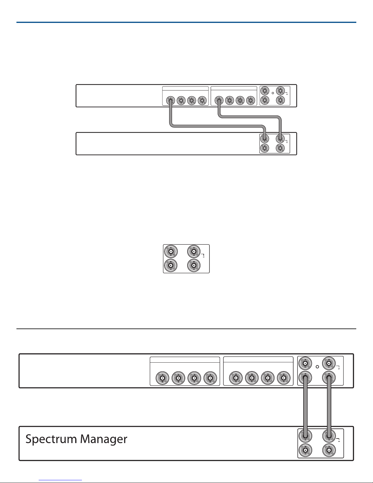
RF Cascade Ports
The RF cascade ports extend the Antenna Distribution System by providing a connection point for additional receivers, Spectrum Managers, or Antenna Distribution Systems.
When Antenna Cascade is set to Auto, the Cascade ports automatically activate when 12 V DC from the antenna input of a connected device is sensed at the
port connection. When the cascade ports are active, a signal splitting loss occurs of 5 dB (max.).
Receivers with RF cascade outputs can extend the antenna signal to additional receivers within the same band.
Adding an AXT600 Spectrum Manager to an Antenna System
Connect the AXT600 Spectrum Manager to the RF Cascade ports of the Antenna Distribution System.
3/92017/10/12
 Loading...