

Shure ANTENNA SETUP User Manual
WIRELESS
SYSTEMS
GUIDE
A Shure Educational Publication
ANTENNA SETUP
By Gino Sigismondi and Crispin Tapia


Wireless Systems Guide for
Table of Contents
Introduction . . . . . . . . . . . . . . . . . . . . . . . . . . . . . . . . . . . . . 4
Section One . . . . . . . . . . . . . . . . . . . . . . . . . . . . . . . . . . . . . 5
Antenna Types . . . . . . . . . . . . . . . . . . . . . . . . . . . . . . . . 5
Omnidirectional Antennas
Unidirectional Antennas. . . . . . . . . . . . . . . . . . . . . 5
Antenna Placement . . . . . . . . . . . . . . . . . . . . . . . . . . . 6
Antenna Spacing
Antenna Height . . . . . . . . . . . . . . . . . . . . . . . . . . . 7
Antenna Orientation . . . . . . . . . . . . . . . . . . . . . . . . 7
Antenna Distribution . . . . . . . . . . . . . . . . . . . . . . . . . . 7
Passive Splitters (2 receivers)
Active Antenna Distribution
(3 or more receivers) . . . . . . . . . . . . . . . . . . . . . . . 8
Antenna Remoting . . . . . . . . . . . . . . . . . . . . . . . . . . . . 8
Antenna Combining . . . . . . . . . . . . . . . . . . . . . . . . . . . 10
Multi-room Antenna Setups
Antenna Combining for
Personal Monitor Transmitters . . . . . . . . . . . . . . . . 10
. . . . . . . . . . . . . . . . . . . . . . . . . . 6
. . . . . . . . . . . . . . . . . . . 5
. . . . . . . . . . . . . . . . . 7
. . . . . . . . . . . . . . . . . . 10
ANTENNA SETUP
Section Two . . . . . . . . . . . . . . . . . . . . . . . . . . . . . . . . . . . . . 12
Diagrams . . . . . . . . . . . . . . . . . . . . . . . . . . . . . . . . . . . 12
2 receivers
3-4 receivers . . . . . . . . . . . . . . . . . . . . . . . . . . . . . 12
5-8 receivers . . . . . . . . . . . . . . . . . . . . . . . . . . . . . 12
9-12 receivers . . . . . . . . . . . . . . . . . . . . . . . . . . . . 13
13-16 receivers . . . . . . . . . . . . . . . . . . . . . . . . . . . 13
Large system: 50 channels . . . . . . . . . . . . . . . . . . 13
Antenna combining:
2-4 systems . . . . . . . . . . . . . . . . . . . . . . . . . . . . . . 14
5-8 systems . . . . . . . . . . . . . . . . . . . . . . . . . . . . . . 14
9-12 systems . . . . . . . . . . . . . . . . . . . . . . . . . . . . 15
13-16 systems. . . . . . . . . . . . . . . . . . . . . . . . . . . . 15
Remote antenna:
100 feet (˜30 m) . . . . . . . . . . . . . . . . . . . . . . . . . . 16
75 feet (˜20 m) . . . . . . . . . . . . . . . . . . . . . . . . . . . 16
50 feet (˜15 m) . . . . . . . . . . . . . . . . . . . . . . . . . . . 16
30 feet (˜10 m) . . . . . . . . . . . . . . . . . . . . . . . . . . . 17
<30 feet (˜10 m) . . . . . . . . . . . . . . . . . . . . . . . . . . 17
About the Authors . . . . . . . . . . . . . . . . . . . . . . . . . . . . 18
. . . . . . . . . . . . . . . . . . . . . . . . . . . . . . . 12
Quick Tips . . . . . . . . . . . . . . . . . . . . . . . . . . . . . . . . . . 11
Suggested Reading . . . . . . . . . . . . . . . . . . . . . . . . . . . 11
Antenna Setup
3
Wireless Systems Guide for
ANTENNA SETUP
Introduction
The world of professional audio is filled with
transducers. A transducer is a device that converts
one form of energy to another. In the case of
microphones and loudspeakers, sound waves are
converted to electrical impulses, and vice versa.
The proliferation of wireless audio systems has
introduced yet another category of transducer to
professional audio, the antenna. As defined in the
ARRL (American Radio Relay League) Antenna
Book, “The purpose of an antenna is to convert
radio-frequency electric current to electromagnetic
waves, which are then radiated into space.”
Attached to a receiving device, antennas can also
work in the reverse fashion, converting the
electromagnetic wave back to an electric current.
This reciprocity is similar to the manner in which
a loudspeaker can also function as a microphone
considerations such as antenna size, orientation,
and proper cable selection, are important
factors not to be overlooked. Without getting too
technical, this guide presents a series of good
practices for most typical wireless audio
applications. Note that these recommendations
only apply to professional wireless systems with
detachable antennas. For entry-level systems
with permanently affixed antennas, antenna
distribution and remote antenna mounting are
simply not possible.
One final note: These recommendations are
useful guidelines to help achieve satisfactory
performance from wireless audio systems, but
not hard-and-fast rules that need to be followed
to the letter. However, if a wireless system fails
when attached to an audio input.
As with any transducer, following certain
guidelines helps ensure maximum performance.
When dealing with radio frequencies in particular,
to operate as expected, it is often due to the
disregard of several of these guidelines,
compounding the negative effects. Rarely
does a system fail to function if only a single
recommendation is overlooked!
Introduction
4
Wireless Systems Guide for
ANTENNA SETUP
SECTION ONE
ANTENNA TYPES
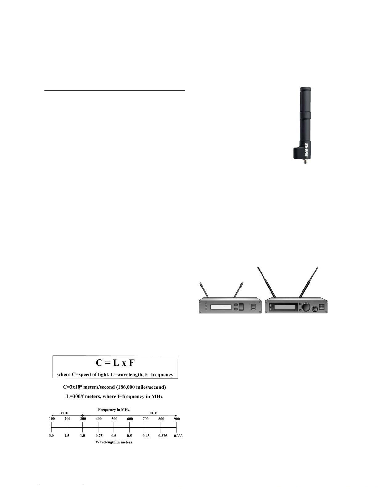
The size of an antenna is directly related to the
wavelength of the frequency to be received. The most
common types used in wireless audio systems are 1/4wave and 1/2-wave omni-directional antennas, and
unidirectional antennas.
Omnidirectional Antennas
The size of a 1/4-wave antenna is approximately
one-quarter of the wavelength of the desired frequency,
and the 1/2-wave is one-half the wavelength. Wavelength
for radio signals can be calculated by dividing the speed of
light by frequency (see “The Wave Equation”). For example,
a 200 MHz wave has a wavelength of approximately 6 feet
(2 m). Therefore, a 1/2-wave receiver antenna would be
about 3 feet (1 m) long, and a 1/4-wave antenna would be
about 18 inches (45 cm). Note that antenna length
typically needs to only be approximate, not exact. For VHF
applications, an antenna anywhere from 14-18 inches
(35-45 cm) is perfectly appropriate as a 1/4-wave
antenna. Since the UHF band covers a much larger range
of frequencies than VHF, 1/4-wave antennas can range
anywhere from 3 to 6 inches (7-15 cm) in length, so using
the proper length antenna is somewhat more important.
For a system operating at 500 MHz, a 1/4-wave antenna
should be about 6 inches (15 cm). Using an antenna
tuned for an 800 MHz system (about 3 inches, 7 cm,
in length) in the same situation would result in less than
optimum pickup. Wideband omnidirectional antennas
that cover almost the entire UHF band are also available
for applications where receivers with different tuning
ranges need to share a common antenna (see “Antenna
Distribution” page 9).
The Wave Equation
1/4-wave antennas should only
be used when they can be mounted
directly to the wireless receiver
or antenna distribution system;
this also includes front-mounted
antennas on the rack ears. These
antennas require a ground plane
for proper reception, which is
a reflecting metal surface of
approximately the same size as the
antenna in at least one dimension.
The base of the antenna must be
electrically grounded to the receiver.
The chassis of the receiver (or
distribution system) provides the
necessary ground plane. Do not use
a 1/4-wave antenna for remote antenna mounting.
A 1/2-wave antenna does not require a ground plane,
making it suitable for remote mounting in any location.
While there is a theoretical gain of about 3 dB over a
1/4-wave antenna, in practice, this benefit is seldom
realized. Therefore, there is no compelling reason to
“upgrade” to a 1/2-wave antenna unless remote antennas
are required for the application.
1/4 wave and 1/2 wave antennas: UHF range
Wideband
omnidirectional
antenna
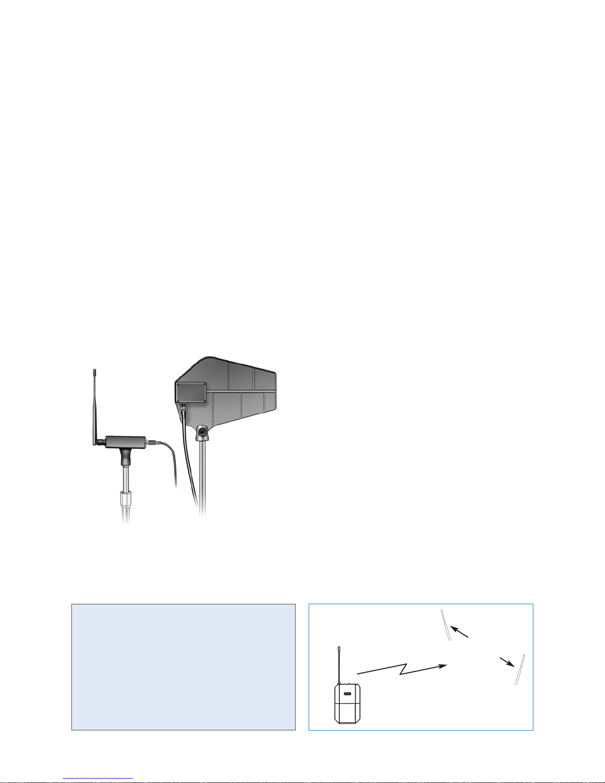
Unidirectional Antennas
A second type of antenna suitable for remote
mounting is a unidirectional, such as yagi or log periodic
antennas. Both types consist of a horizontal boom and
multiple transverse elements. They can provide up to 10
dB more gain than a 1/4-wave antenna, and can also reject
interfering sources from other directions by as much as 30
dB. Yagi antennas are rarely used in wireless microphone
applications due to their quite narrow bandwidth, usually
just a single TV channel (6 MHz). The log periodic antenna
achieves greater bandwidth by using multiple dipoles
whose size and spacing vary in a logarithmic progression.
A longer boom and more elements result in greater
bandwidth and directivity. Some unidirectional antennas
have built-in amplifiers to compensate for losses due to
long cable runs.
5
Wireless Systems Guide for
ANTENNA SETUP
With regard to wireless microphone applications,
unidirectional antennas are typically only employed in
UHF systems. Directional antennas are somewhat
frequency specific, so some care must be taken in
selecting the proper antenna to cover the required
frequencies. A directional VHF antenna is 3-5 feet
(1-2 m) wide (just like a roof-mounted television
antenna), which makes mounting a mechanically
cumbersome task. Note that these antennas should be
mounted with the transverse elements in the vertical
direction, rather than horizontal as in a television
application, because the transmitting antennas are
usually also vertical. Unidirectional antennas are
primarily used for long range applications. A minimum
distance of 50 feet (15 m) is recommended between
transmitter and unidirectional antennas.
ANTENNA PLACEMENT
Most wireless receivers have their primary antenna
inputs on the back of the receiver. Since diversity receivers
are discussed here almost exclusively, there will be both
an A antenna input and a B antenna input on the rear
panel of the receiver. BNC connections are most often
used for antenna inputs, although some older (primarily
VHF) systems may have used PL-259 connectors.
Rack-mountable receivers often provide pre-cut holes on
the rack ears to accommodate antenna connections for
front-mounting the antennas. Short coaxial cables and
bulkhead adapters with the proper connector type are all
that is needed to bring the antennas to the front.
When deciding where to mount antennas, always try
to maintain line of sight between the receiving and
transmitting antennas. For example, if the back of the rack
faces the performance area, then rear-mounting the
antennas will provide better line of sight. If the front of the
rack faces the performance area, then front-mounting may
be better, unless a front door to the rack needs to be
closed. Metal equipment racks will block RF from reaching
the antennas mounted inside. Rear-mounted antennas
may not work inside of a metal equipment rack. If the
receiver is not rack-mounted at all, then simply maintain
line of sight, that is, the receiving antennas should be
directly visible from the transmitting position.
Antenna Spacing
Antennas should be separated from each other by a
minimum of one quarter wavelength – about 16 inches (40
cm) for VHF units and about 4 inches (10 cm) for UHF
units. This helps ensure adequate diversity performance.
Diversity reception can be improved by separating
the antennas further, but beyond one full wavelength
1/2 wave
(with amplifier)
Summary:
• 1/4-wave antenna –must be mounted on
receiver; do not remote mount.
• 1/2-wave antenna –suitable for remote
applications.
• Unidirectional antenna –also suitable for
remote mount, provides additional gain.
6
log periodic
the advantage becomes negligible. However, greater
separation may be useful if it results in more strategic
antenna location. For example, increasing separation to
ensure line-of-sight with at least one of the antennas from
any location in the room.
Adequate spacing
Minimum: > 1/4 wavelength
Best: > 1 wavelength
VHF: 16”
UHF: 4”
 Loading...