

Page 1
General Description
The ANIUSB-MATRIX Audio Network Interface provides connections for
USB, Dante™ , and analog audio sources. Collaborate and connect with all
audio devices on a single network, with support for wireless microphones,
computers, mobile devices, video codecs, and loudspeaker systems. Connect
Safety Information
IMPORTANT SAFETY INSTRUCTIONS
1. READ these instructions.
2. KEEP these instructions.
3. HEED all warnings.
4. FOLLOW all instructions.
5. DO NOT use this apparatus near water.
6. CLEAN ONLY with dry cloth.
7. DO NOT block any ventilation openings. Allow sufficient distances for
adequate ventilation and install in accordance with the manufacturer’s
instructions.
8. DO NOT install near any heat sources such as open flames, radiators,
heat registers, stoves, or other apparatus (including amplifiers) that produce heat. Do not place any open flame sources on the product.
9. DO NOT defeat the safety purpose of the polarized or grounding type
plug. A polarized plug has two blades with one wider than the other. A
grounding type plug has two blades and a third grounding prong. The
wider blade or the third prong are provided for your safety. If the provided
plug does not fit into your outlet, consult an electrician for replacement
of the obsolete outlet.
10. PROTECT the power cord from being walked on or pinched, particularly
at plugs, convenience receptacles, and the point where they exit from
the apparatus.
11. ONLY USE attachments/accessories specified by the manufacturer.
12. USE only with a cart, stand, tripod, bracket, or table specified by the
manufacturer, or sold with the apparatus. When a cart is used, use caution
when moving the cart/apparatus combination to avoid injury from tip-over.
ANIUSB-Matrix
Audio Network Interface
with a single network cable to receive audio and power through Power over
Ethernet (PoE). A browser-based web application controls audio and network
settings from any computer connected to the same network.
13. UNPLUG this apparatus during lightning storms or when unused for long
periods of time.
14. REFER all servicing to qualified service personnel. Servicing is required
when the apparatus has been damaged in any way, such as power
supply cord or plug is damaged, liquid has been spilled or objects have
fallen into the apparatus, the apparatus has been exposed to rain or
moisture, does not operate normally, or has been dropped.
15. DO NOT expose the apparatus to dripping and splashing. DO NOT put
objects filled with liquids, such as vases, on the apparatus.
16. The MAINS plug or an appliance coupler shall remain readily operable.
17. The airborne noise of the Apparatus does not exceed 70dB (A).
18. Apparatus with CLASS I construction shall be connected to a MAINS
socket outlet with a protective earthing connection.
19. To reduce the risk of fire or electric shock, do not expose this apparatus
to rain or moisture.
20. Do not attempt to modify this product. Doing so could result in personal
injury and/or product failure.
21. Operate this product within its specified operating temperature range.
This symbol indicates that dangerous voltage constituting a risk of
electric shock is present within this unit.
This symbol indicates that there are important operating and maintenance instructions in the literature accompanying this unit.
Getting Started
This device features a browser-based web application, which controls audio and network properties. Upon completing this basic setup process, you will be able
to:
• Access the web application to customize audio settings, signal routing, and network properties
• Use Dante™ Controller software to connect with other Dante devices and pass audio
• Access additional configuration information
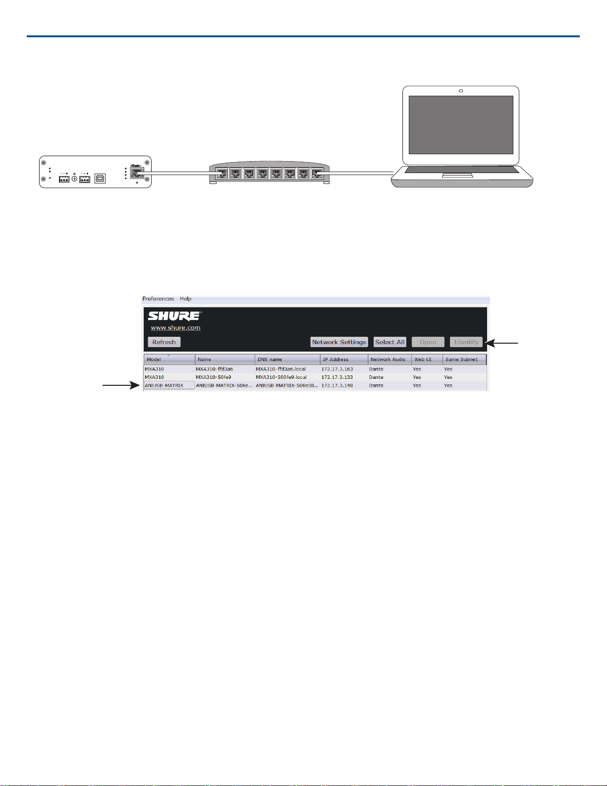
Step 1: Connect to a Network
1. Use an Ethernet cable (CAT5e or higher) to connect the ANIUSB-MATRIX to a network switch.
Note: The network switch must provide Power over Ethernet (PoE). Make sure to connect to a PoE port, since many switches do not supply power on all
ports.
2. Connect a computer to the network switch with an Ethernet cable
1/27©2017 Shure Incorporated
Page 2
sig/clip
power
reset
PoE
network
network audio
encryption
line in
in
out
usb
line out usb
Step 2: Access the Web Application
Select the device
Identify
1. Download and install the Shure Device Discovery application (http://www.shure.com)
2. Open the Shure Device Discovery application
3. Double-click the device to open the web application.
Tip: If setting up multiple Shure devices, use the Identify button in the application to flash the lights on the device.
Shure IncorporatedANIUSB-Matrix Audio Network Interface
Step 3: Connect Devices in Dante Controller Software
1. Download and install Dante Controller Software from http://www.audinate.com
2. Use Dante Controller to create connections with other Dante devices
Note: Refer to the Dante Controller user guide for more information on channel routing (available at http://www.audinate.com/resources/technical-documentation)
2017/12/222/27
Page 3
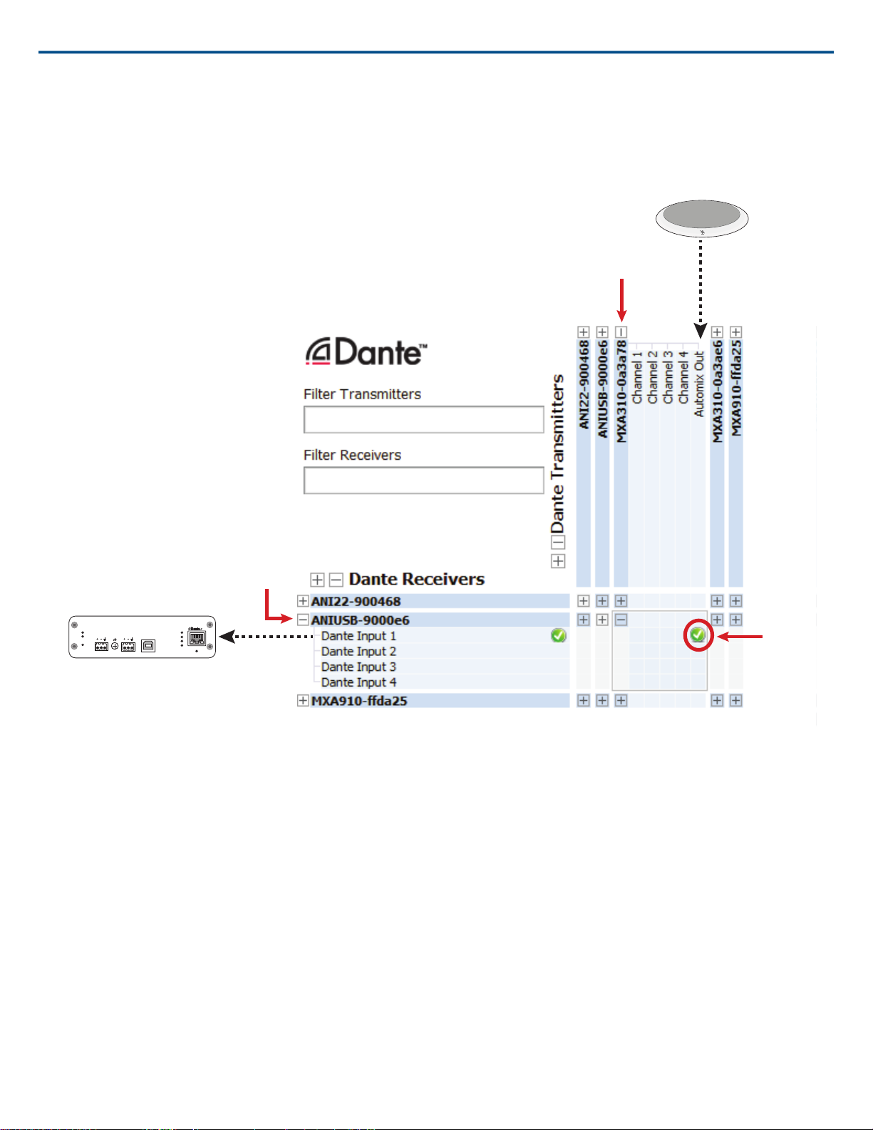
Example: Connecting the ANIUSB-MATRIX and Shure MXA310
sig/clip
power
reset
PoE
network
network audio
encryption
line in
in
out
usb
line out usb
MXA310
ANIUSB-MATRIX
Shure IncorporatedANIUSB-Matrix Audio Network Interface
1. Find the MXA310 in the list of Dante transmitters, and select the plus sign (+) to show all channels.
2. Find the ANIUSB-MATRIX in the list of Dante receivers, and select the plus sign (+) to show all channels.
3. Check the box where the MXA310 AUTOMIX OUT and the ANIUSB-MATRIX DANTE INPUT 1 intersect
Step 4: Configure Audio
The final configuration steps will vary, depending on the devices used with the ANIUSB-MATRIX. These steps may include:
• Connecting analog and USB audio devices
• Using the matrix mixer to customize signal routing
• Adjusting input and output levels
• Viewing the entire signal path and modifying settings in schematic view
• Applying equalization to maximize speech clarity
For these steps, comprehensive information is available in the help section of the web application.
3/272017/12/22
Page 4
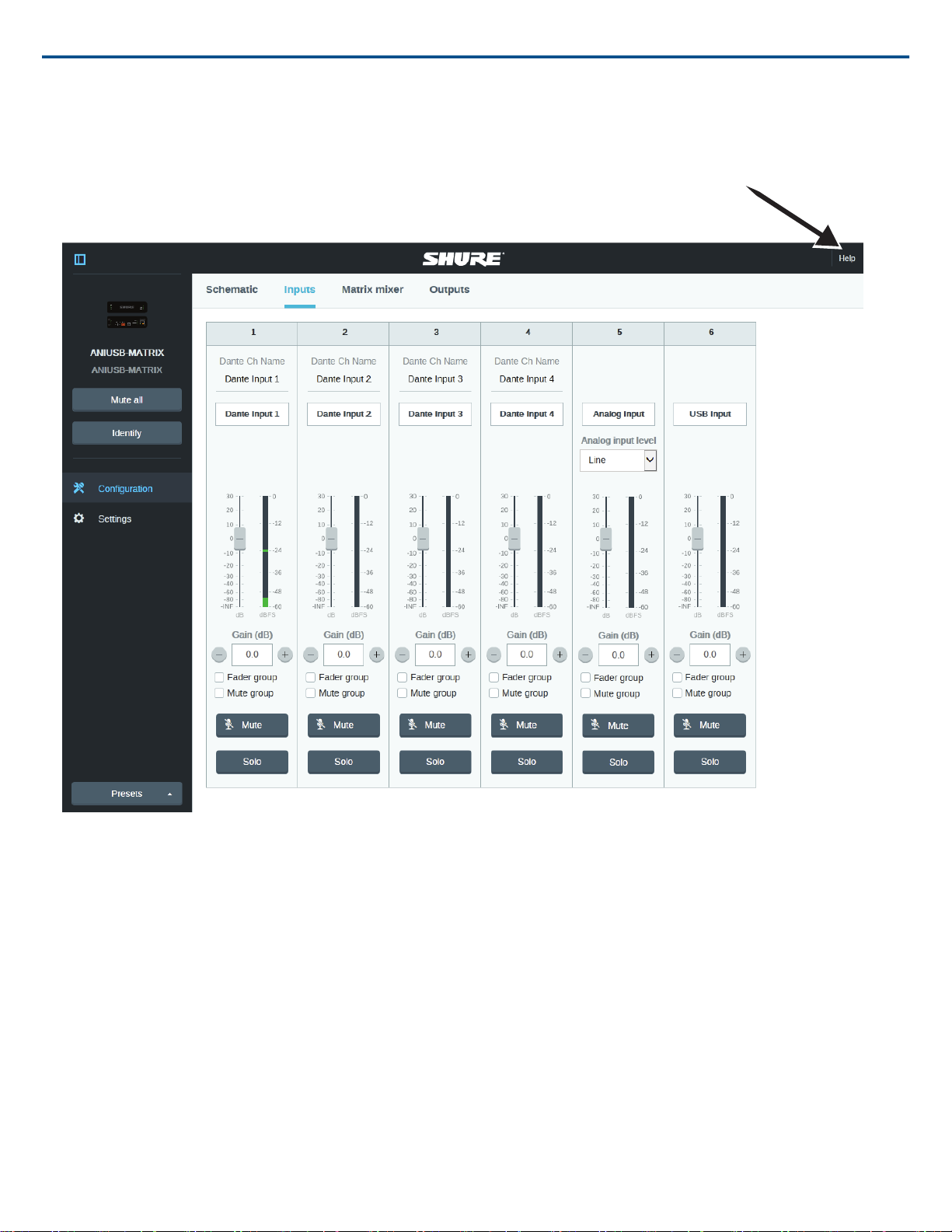
Access the help section
Shure IncorporatedANIUSB-Matrix Audio Network Interface
2017/12/224/27
Page 5
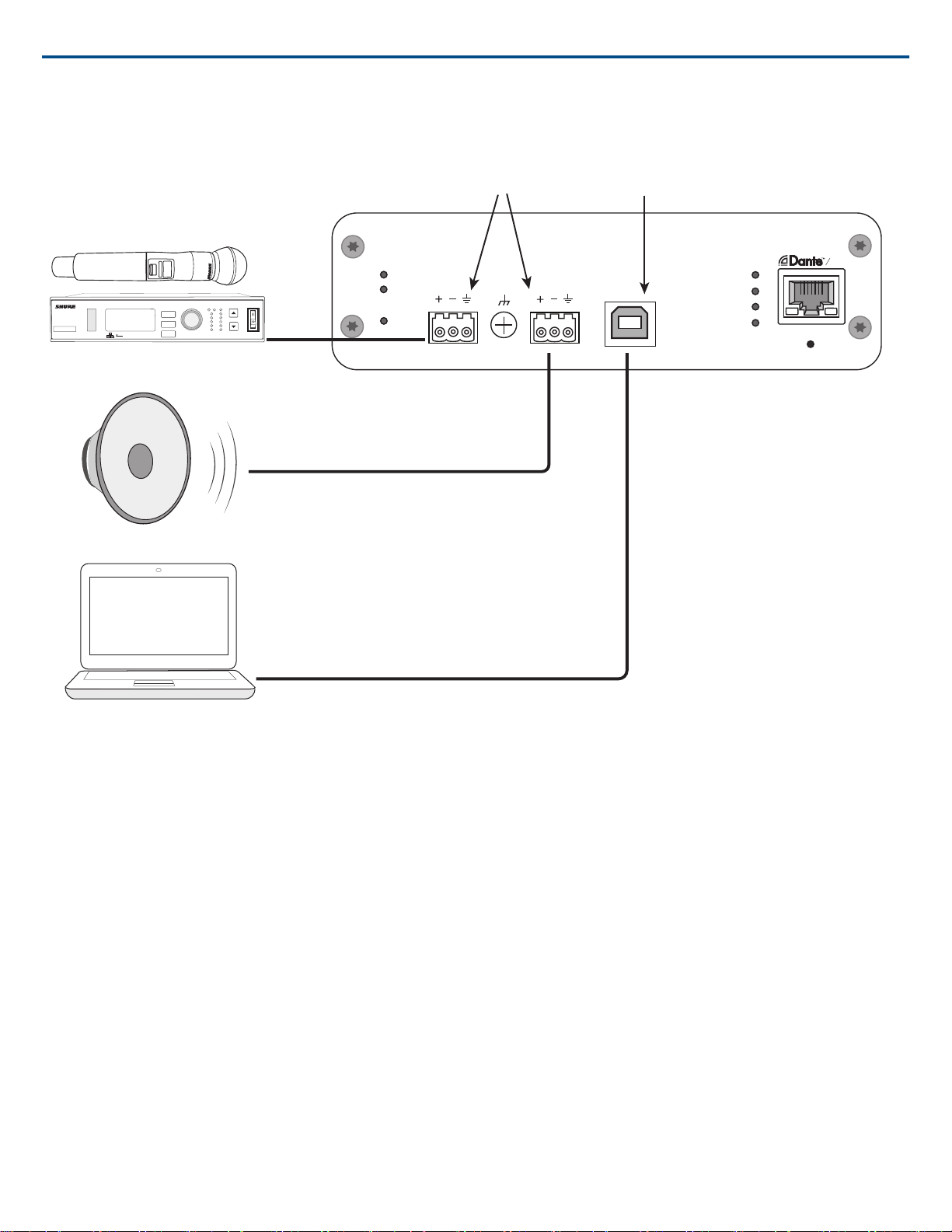
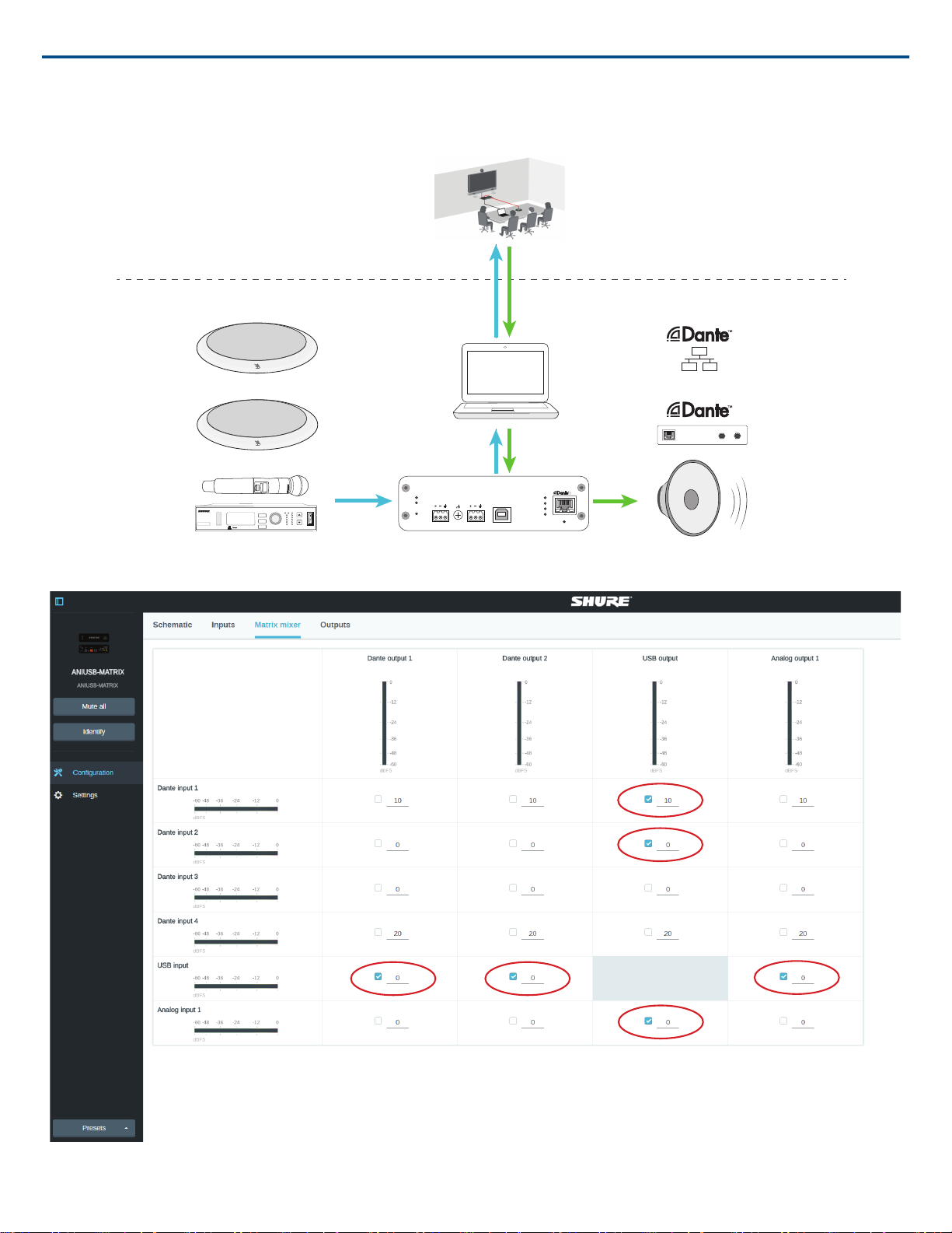
Example: Connecting Loudspeakers, Wireless Microphones, and a Computer
ULXD4
Digital Wireless Receiver
push
control
ENTER
EXIT
SCAN
RF
A B
OL
OL
gain poweraudio
IR
on
ULXD2
sig/clip
power
reset
PoE
network
network audio
encryption
INPUT
in
out
usb
OUTPUT USB
Shure IncorporatedANIUSB-Matrix Audio Network Interface
1. Connect analog equipment (such as loudspeakers or wireless microphone systems) to the analog input and output. Refer to the hardware section in this
guide for information on connections and LED metering.
2. Connect a computer to the USB port
3. In the ANIUSB-MATRIX web application, open the matrix mixer to make connections between devices.
Note: Some connections are established in the matrix mixer by default. Refer to the matrix mixer help topic in the web application for additional information.
4. In the ANIUSB-MATRIX web application, adjust input and output levels and perform a sound check. Refer to the help topics in the web application for additional information.
Get More Information
Now that the basic setup is complete, you should have access to the web application and be able to pass audio between devices. More comprehensive information
is available online and in the help section, including:
• Maximizing audio quality with the built-in parametric equalizer
• External control system command strings
• Signal routing
• System scenario diagrams
• Software configuration
• Networking information
• Troubleshooting
• Replacement parts and accessories
The complete user guide is available at http://pubs.shure.com/guide/ANIUSB-MATRIX
5/272017/12/22
Page 6
sig/clip
power
reset
PoE
network
network audio
encryption
INPUT
in
out
usb
OUTPUT USB
௦
Shure IncorporatedANIUSB-Matrix Audio Network Interface
Hardware and Installation
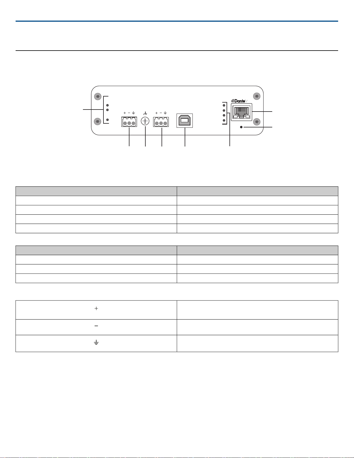
Rear Panel
① Level Indicators (Signal/Clip)
Tri-color LEDs indicate the audio signal level for the analog channels and connectivity status for the USB channel. Adjust output levels in the web application
to avoid clipping.
Audio Signal LevelLED State
less than -60 dBFSOff
-60 dBFS to -18 dBFSGreen
-18 dBFS to -6 dBFSYellow
-6 dBFS or moreRed
Note: The input and output LEDs stay off when metering is set to Post Fader and the channel is muted in the web application.
StatusLED State
No USB device connectedOff
USB device operating successfullyGreen
Problem detected with connected USB audio deviceRed (flashing)
② Audio Input (Block Connector)
Block Pin Assignments:
Audio +
Audio -
Audio ground
③ Chassis Ground Screw
Provides an optional connection for microphone shield wire to chassis ground.
④ Audio Output (Block Connector)
Balanced audio output connects to an analog device. Set the output level in the web application to match the input sensitivity of the analog device.
Note: See front panel labels for block connector assignments.
⑤ USB Port
Connects to a computer to send and receive any combination of input and output audio channels.
⑥ LED Indicators
Power:Power over Ethernet (PoE) present
Note: Note: Use a PoE injector if your network switch does not supply PoE.
Network: Network connection active
2017/12/226/27
Page 7

Network Audio: Dante™ audio present on the network
Note: Error details are available in the event log in the web application.
ActivityLED Status
No active signalOff
Device is operating successfullyGreen
Error has occurred. See event log for details.Red
Encryption:
ActivityLED Status
Audio not encryptedOff
Successful encrypted audio connection with another deviceGreen
Encryption error. Possible causes:
Red
⑦ Dante Network Port
Connects to a network switch to receive Dante™ audio, Power over Ethernet (PoE), and data from the control software.
⑧ Reset Button
Resets the device settings back to the factory default
•Encryption is enabled on one device and not on another
•Passphrase mismatch
Shure IncorporatedANIUSB-Matrix Audio Network Interface
Power Over Ethernet (PoE)
Power Over Ethernet
This device requires PoE to operate. It is compatible with both Class 0 and Class 3 PoE sources.
Power over Ethernet is delivered in one of the following ways:
• A network switch that provides PoE
• A PoE injector device
Reset
The reset button is located inside a small hole in the rear panel. Use a paperclip or other small tool to press the button.
There are two hardware reset functions:
Network reset (press button for 4-8 seconds)
Resets all Shure control and audio network IP settings to factory defaults
Full factory reset (press button for longer than 8 seconds)
Restores all network and web application settings to the factory defaults.
Software Reset Options
To simply revert settings without a complete hardware reset, use one of the following options:
Reboot Device:In the web application (settings > factory reset), there is a Reboot Device button, which simply power-cycles the device as if it were unplugged
from the network. All settings are retained when the device is rebooted.
Default Settings: To revert audio settings back to the factory configuration (excluding Device Name, IP Settings, and Passwords), select Load Preset and
choose the default settings preset.
Installation and Rack Mounting
Two mounting solutions are available for installing the Audio Network Interface:
CRT1 19" Rack Tray (optional accessory): Supports up to 3 devices; mountable in a rack or under a table
Single-unit Mounting Tray (included accessory):Supports a single device for mounting under a table
Securing the Devices
Use the included screws from the mounting hardware kit to secure the Audio Network Interfaces. Audio Network Interfacescan be mounted to face either direction.
Insert the screws from the bottom in the appropriate holes, according to the following diagrams:
7/272017/12/22
Page 8
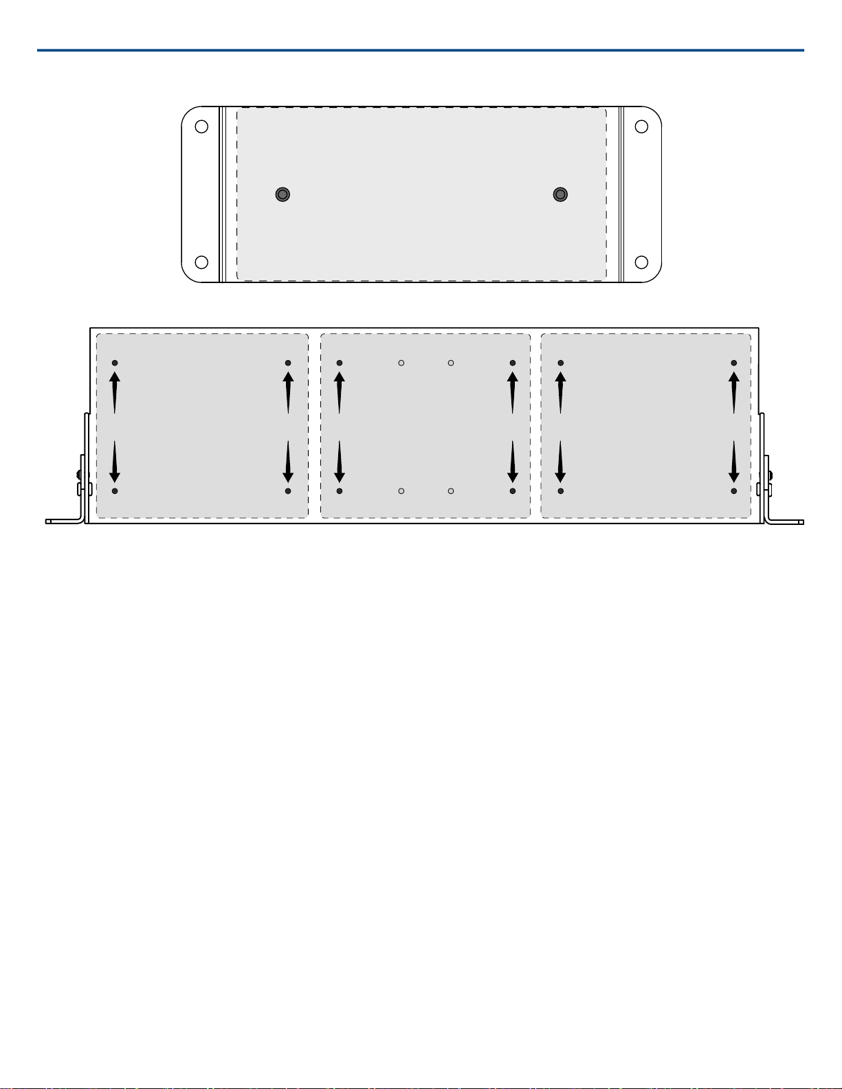
Align the holes as shown for securing a single device in the single-unit mounting tray
Device 1 Device 2 Device 3
Shure IncorporatedANIUSB-Matrix Audio Network Interface
Align the holes as shown for securing up to three devices in the 19" rack tray.
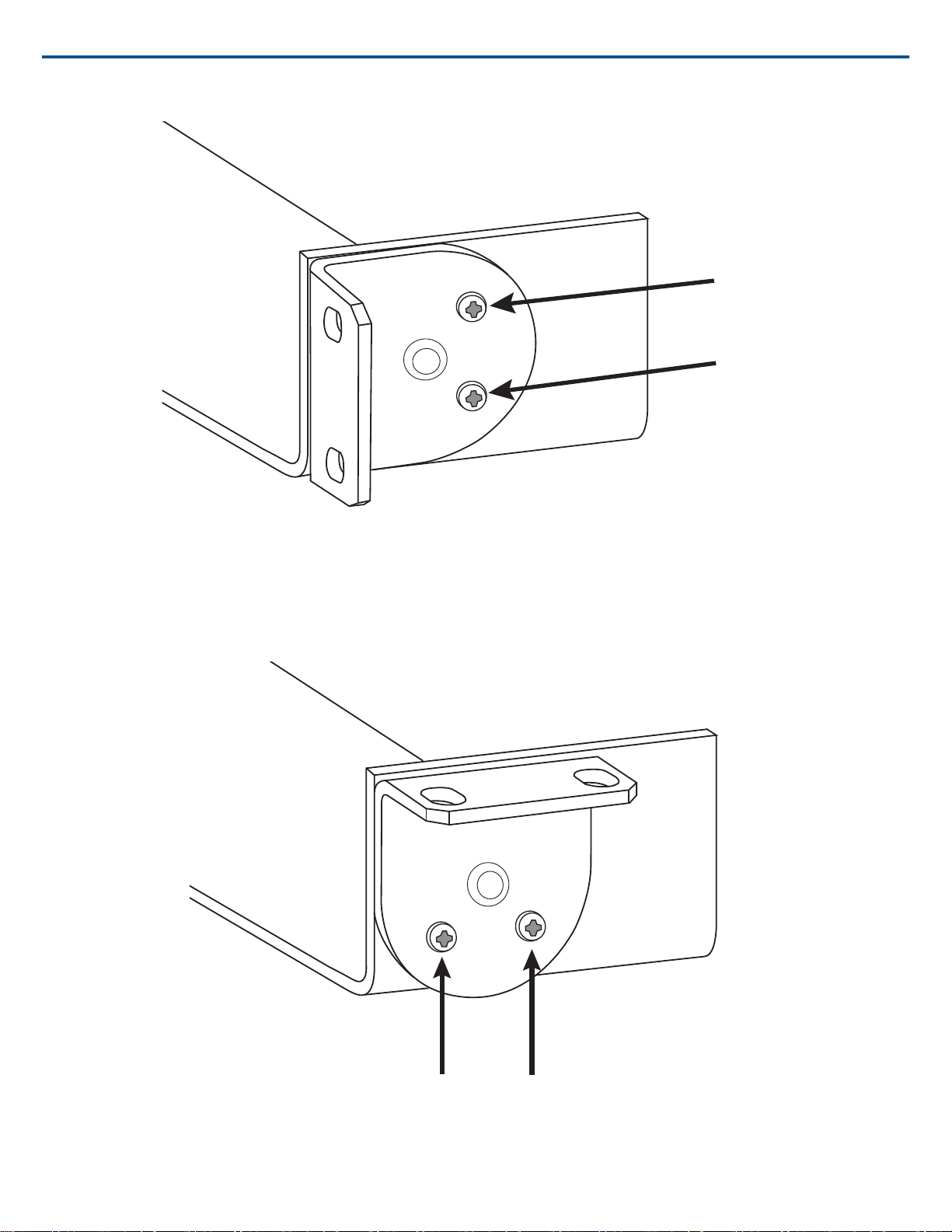
Rack Ear Configuration
A combination of up to 3 Audio Network Interfaces can be mounted in a single 19-inch rack space. The adjustable rack ears support mounting in a standard
equipment rack or underneath a table.
Standard 19" Rack Mount
1. Align the ears with the mounting holes pointed forward.
2. Install the two screws that hold the ear to the tray as shown.
2017/12/228/27
Page 9
Shure IncorporatedANIUSB-Matrix Audio Network Interface
Under-table Mounting
1. Align the ears with the mounting holes pointed upward.
2. Install the two screws that hold the ear to the tray as shown.
Installing Underneath a Table
1. Hold the tray in the desired location under a table
2. Use a pencil to mark the location of the mounting holes on the table.
9/272017/12/22
Page 10

3. Drill 4 holes for the screws. The diameter of the holes in the tray are 7.1 mm.
sig/clip
power
reset
PoE
network
network audio
encryption
line in
in
out
usb
line out usb
ULXD4
Digital Wireless Receiver
push
control
ENTER
EXIT
SCAN
RF
A B
OL
OL
gain poweraudio
IR
on
ULXD2
4. Install the components into the tray
5. Install with 4 screws to secure the tray underneath the table
Device Identification
Device Identify
To identify the hardware by flashing the lights, select the Identify button in
the device options section.
Signal Flow and Connections
Connections and Signal Flow
Shure IncorporatedANIUSB-Matrix Audio Network Interface
① Computer
Compatible with Mac and PC
The host computer sends and receives audio through conferencing software. All signals are passed through a single USB connection, with input sources and
output devices (dante and analog) routed through Dante Controller.
② Analog Input Sources
Analog sources (such as wireless microphones or any line-level devices) connect to the analog line input.
③ Analog Output Devices
Loudspeakers, amplifiers, or recording devices connect to the analog line output.
2017/12/2210/27
Page 11

Shure IncorporatedANIUSB-Matrix Audio Network Interface
④ Dante-enabled Equipment
Dante microphones, such as the Shure Microflex Advance ceiling and table arrays connect to the network switch and can be routed through the USB channel
on the ANIUSB.
⑤ Control CPU
A computer connected to the network accesses the web application to control the channel levels and processing.
⑥ Network Switch
The network switch provides Power over Ethernet (PoE) to the ANIUSB, while also supporting all other Dante-enabled audio equipment.
Connecting a USB Device
The USB port connects the host computer to the entire room audio system, including microphones and loudspeakers.
When the ANIUSB-MATRIX is connected for the first time, the computer recognizes it as a USB audio device. You may need to select it as the input/output
(recording/playback) device to pass audio. Assign the ANIUSB-MATRIX as the default device to ensure it passes audio every time it is plugged in. Refer to the
manual for your computer to configure the audio settings.
Adapter Compatibility
This device is compatible with USB-B to USB-C adapters. Using an adapter is only recommended for desktop and laptop computers, as many mobile devices
do not support bi-directional audio through USB or lightning ports.
Routing Audio Channels Through the USB Port
Audio channel routing is managed through Dante™ Controller software and the matrix mixer in the ANIUSB-MATRIX web application.
Step one: Dante Controller
1.
Open Dante Controller and route Dante-enabled devices (such as Microflex®Advance™ and Microflex
Dante receive channels. Name the channels in the ANIUSB-MATRIX web application to keep track of devices.
2. If the ANIUSB-MATRIXneeds to send channels to Dante-enabled devices (such as an amplifier, loudspeaker, or recording device on the network), route
the ANIUSB-MATRIX Dante transmit channels to the appropriate receiving devices in Dante Controller.
®
Wireless microphones) to the ANIUSB-MATRIX
Step two: matrix mixer
1. Open the matrix mixer section in the ANIUSB-MATRIXweb application to route Dante and analog channels through the USB port.
2. Assign the USB Input channel (far-end audio) to the appropriate outputs. If recording a meeting, be sure to route the near end microphones in addition to
the USB input to the recording device.
Note: Refer to the matrix mixer topic for additional information and signal routing examples.
Encryption
Audio is encrypted with the Advanced Encryption Standard ( AES -256), as specified by the US Government National Institute of Standards and Technology
(NIST) publication FIPS-197. Shure devices that support encryption require a passphrase to make a connection. Encryption is not supported with third-party
devices.
To activate encryption:
1. Open the Settings menu and select the General tab.
2. Select the Enable Encryption checkbox.
3. Enter a passphrase. All devices must use the same passphrase to establish an encrypted connection.
Important: For encryption to work:
• Encryption must be universally enabled or disabled on all connected Shure devices
• AES67 must be disabled in Dante Controller to turn encryption on or off. AES67 encryption is currently not supported.
Audio Settings
Schematic View
The schematic view in the web application provides an overview of the entire signal chain, with the ability to adjust settings and monitor signals.
Adjusting Settings
Right-click an input, output, or processing block to access the following options:
Per Channel
Copy / paste
11/272017/12/22
Page 12

Shure IncorporatedANIUSB-Matrix Audio Network Interface
Copy and paste settings between items. For example, set the equalizer curve on the USB output, and then use the same setting for the analog output. Or, copy
the gain and mute status from one input channel to several others.
Mute / unmute
Mutes or activates the channel
Enable / disable
Turns processing on or off (applies to equalizer and limiter only)
Edit
Opens the dialog to adjust parameters
Global (right-click in blank area)
Mute all inputs
Mutes all input channels
Mute all outputs
Mutes all output channels
Close all dialogs
Clears all open dialogs from the workspace
Customizing the Workspace
Create a custom environment to monitor and control a set of inputs, outputs, and processing blocks from a single screen. There are two ways to break out dialogs:
• Right click > edit
• Double-click the input, output, or processing block.
Open as many dialogs as you need to keep important controls available.
Metering and Signal Flow
A meter appears underneath each input and output to indicate signal levels (dBFS).
The lines connecting inputs and outputs to the matrix mixer appear colored when connections are established. When a signal is not routed, the line appears
gray. Use these tools to troubleshoot audio signals and verify connections and levels.
Matrix Mixer
The matrix mixer routes audio signals between inputs and outputs, for simple and flexible routing:
• Send a single input channel to multiple outputs
• Send multiple input channels to a single output
Routing Channels
Connect inputs and outputs by selecting the box where they intersect.
Important: Dante devices must be routed in Dante Controller software to pass audio to or from a Dante device.
Default Setting
• All Dante input channels and analog Input channel > USB output
• USB input channel and analog input channel > analog output
Crosspoint Gain
Crosspoint gain adjusts the gain between a specific input and output, to create separate submixes without changing input or output fader settings. Select the
dB value at any crosspoint to open the gain adjustment panel.
Gain staging: input fader > crosspoint gain > output fader
Example Scenario
Hosting a meeting with a computer:
Near-end audio from Dante microphones (Shure MXA 310) and an analog source (Shure wireless microphone system) are both routed to the USB input and
sent to the far end.
Far-end audio from the computer (USB input in the matrix mixer) can be sent to analog or Dante-enabled amplifiers and loudspeakers.
Record meeting audio from all locations by routing all sources to a recording device or computer on the network.
2017/12/2212/27
Page 13
sig/clip
power
reset
PoE
network
network audio
encryption
line in
in
out
usb
line out usb
ULXD4
Digital Wireless Receiver
push
control
ENTER
EXIT
SCAN
RF
A B
OL
OL
gain poweraudio
IR
on
ULXD2
USB Output
USB Input
Inputs
Outputs
Dante Input 1
Dante Input 2
Analog Input
Dante Output 1
Dante Output 2
Analog Output
Far End
Shure IncorporatedANIUSB-Matrix Audio Network Interface
13/272017/12/22
Page 14

Shure IncorporatedANIUSB-Matrix Audio Network Interface
Mute and Fader Groups
Mute Groups
Check the Mute group box to add the channel to a group. Muting any channel within the Mute group mutes all channels in the group.
Fader Groups
Check the Fader group box to add the channel to a group. All faders within the group are linked, and move together when a single fader is adjusted.
Adjusting Input levels
Input Levels
Levels for analog and Dante™ channels are adjustable in the Input tab.
To monitor input levels before they reach the ANIUSB-MATRIX, set the metering to pre-fader in the settings menu. When adjusting the faders, set metering to
post-fader.
Dante™ Sources
1. Check the source level before it reaches the Network Interface:
⁃ Verify that the networked microphones or other Dante™ sources are operating at nominal output levels.
⁃ Levels for Microflex Advance™ microphones are adjustable through their web application.
2. Adjust the digital gain in the Network Interface web application:
⁃ Use the faders or manually enter a gain value.
⁃ The digital gain adjusts the level of the signal before it reaches the matrix mixer.
⁃ Mix the levels as high as possible without the loudest channel reaching the peak level (0 dB) on the meter.
Note: The matrix mixer provides crosspoint gain, to adjust separate submixes for different outputs.
Analog Sources
Before you begin, verify that levels from the analog devices with adjustable output levels are operating at nominal levels. The fader adjusts the digital gain before
the signal reaches the matrix mixer.
1. Match the analog input level setting according to the incoming signal level:
Line (+4 dBu)
Aux (-10 dBV)
2. Use the fader (digital gain) to adjust the mix going to the USB or Dante output channels.
Adjusting Output Levels
Output Levels
Tip: Set the metering to post-fader in the settings menu to adjust output levels.
Adjust faders in the Outputs section as high as necessary, but make sure to avoid clipping (when the signal reaches 0 dBFS). Always adjust the input gain and
crosspoint gain in the matrix mixer before the output gain.
Analog output level:Select Line, Aux, or Mic level output signal to match the sensitivity of the receiving device.
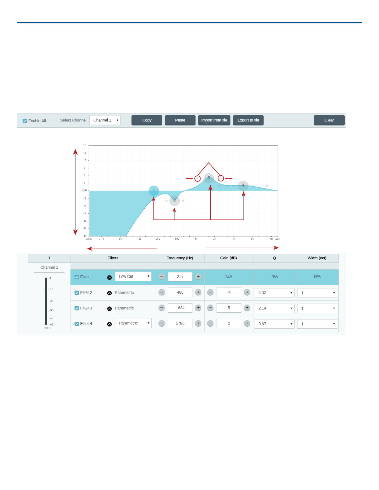
Parametric Equalizer
Maximize audio quality by adjusting the frequency response with the parametric equalizer.
Common equalizer applications:
• Improve speech intelligibility
• Reduce noise from HVAC systems or video projectors
• Reduce room irregularities
• Adjust frequency response for reinforcement systems
Setting Filter Parameters
Adjust filter settings by manipulating the icons in the frequency response graph, or by entering numeric values. Disable a filter using the check-box next to the
filter.
Filter Type
Only the first and last band have selectable filter types.
Parametric: Attenuates or boosts the signal within a customizable frequency range
Low Cut: Rolls off the audio signal below the selected frequency
Low Shelf: Attenuates or boosts the audio signal below the selected frequency
High Cut: Rolls off the audio signal above the selected frequency
High Shelf: Attenuates or boosts the audio signal above the selected frequency
2017/12/2214/27
Page 15
Frequency
Filters
Frequency
Gain
Q
Width
Select the center frequency of the filter to cut/boost
Gain
Adjusts the level for a specific filter (+/- 30 dB)
Q
Adjusts the range of frequencies affected by the filter. As this value increases, the bandwidth becomes thinner.
Width
Adjusts the range of frequencies affected by the filter. The value is represented in octaves.
Note: the Q and width parameters affect the equalization curve in the same way. The only difference is the way the values are represented.
Shure IncorporatedANIUSB-Matrix Audio Network Interface
Copy, Paste, Import, and Export Equalizer Channel Settings
These features make it simple to use effective equalizer settings from a previous installation, or simply accelerate configuration time.
Copy and Paste
Use to quickly apply the same PEQ setting across multiple channels.
1. Select the channel from the pull-down menu in the PEQ screen.
2. Select Copy
3. In the pull-down menu, select the channel to apply the PEQ setting and select Paste.
Import and Export
Use to save and load PEQ settings from a file on a computer. This is useful for creating a library of reusable configuration files on computers used for system
installation.
15/272017/12/22
Page 16

Export
Choose a channel to save the PEQ setting, and select Export to file.
Import
Choose a channel to load the PEQ setting, and select Import from file.
Equalizer Applications
Conferencing room acoustics vary based on room size, shape, and construction materials. Use the guidelines in following table.
Suggested SettingsEQ Application
Add a high shelf filter to boost frequencies greater than 1 kHz by 3-6 dBTreble boost for improved speech intelligibility
Add a low cut filter to attenuate frequencies below 200 HzHVAC noise reduction
Identify the specific frequency range that "excites" the room:
1.Set a narrow Q value
Reduce flutter echoes and sibilance
Reduce hollow, resonant room sound
frequencies between 1 kHz and 6 kHz to pinpoint the range of flutter echoes
minimize the unwanted room sound
Identify the specific frequency range that "excites" the room:
frequencies between 300 Hz and 900 Hz to pinpoint the resonant frequency
minimize the unwanted room sound
2.Increase the gain to between +10 and +15 dB, and then experiment with
or sibilance
3.Reduce the gain at the identified frequency (start between -3 and -6 dB) to
1.Set a narrow Q value
2.Increase the gain to between +10 and +15 dB, and then experiment with
3.Reduce the gain at the identified frequency (start between -3 and -6 dB) to
Shure IncorporatedANIUSB-Matrix Audio Network Interface
Custom Presets
Use presets to quickly save and recall settings. Up to 10 presets can be stored on each device to match various seating arrangements. A preset saves all device
settings except for the Device Name, IP Settings, and Passwords. Importing and exporting presets into new installations saves time and improves workflow.
When a preset is selected, the name displays above the preset menu. If changes are made, an asterisk appears next to the name.
Note: Use the default settings preset to revert to the factory configuration (excludes Device Name, IP Settings, and Passwords).
Open the presets menu to reveal preset options:
save as preset:
Saves settings to the device
load preset:
Opens a configuration from the device
import from file:
Downloads a preset file from a computer onto the device. Files may be selected through the browser or dragged into the import window.
export to file:
Saves a preset file from the device onto a computer
Using A Password
All settings are configurable by default. To protect settings with a password,
open the Settings menu and select the Generaltab. In this screen, passwords
can be created or changed.
Once a password has been set, a Read-Only option appears on the log-in
screen. In Read-Only mode, device parameters can be viewed, but not edited.
Device identification remains active.
Networking and Dante
• A unicast flow is a point-to-point connection between two devices,
Dante™ Transmit Flows
Dante Flows
This device supports up to two transmit flows and two receive flows. A
single flow consists of up to four channels, through either a unicast or multicast transmission.
supporting up to four channels per flow.
• A multicast flow is a one-to-many transmission, which supports sending
up to four channels to multiple receiving devices across the network.
Shure Device Applications
This device can connect with up to two Dante devices.
2017/12/2216/27
Page 17

Shure IncorporatedANIUSB-Matrix Audio Network Interface
The Shure MXA310, ANI22, ANIUSB-MATRIX and ANI4IN support multicast
transmission. This means that flows can transmit to multiple devices -- as
many as the network can support. If using unicast flows, each of these devices
can connect with up to two Dante receiver devices.
The Shure ANI4OUT connects with up to two Dante transmitter devices.
Pushing Device Names to the Dante Network
To send a device name to appear in Dante Controller, go to Settings>General
and enter a Device Name. Select Push to Dante to send the name to appear
on the network.
Note: names appear in Dante Controller with "-d" attached.
ANIUSB Command Strings
The device is connected via Ethernet to a control system, such as AMX, Crestron or Extron.
Connection: Ethernet (TCP/IP; select “Client” in the AMX/Crestron program)
Port: 2202
Conventions
The device has 4 types of strings:
GET
Finds the status of a parameter. After the AMX/Crestron sends a GET command, the ANIUSB responds with a REPORT string
SET
Changes the status of a parameter. After the AMX/Crestron sends a SET command, the ANIUSB will respond with a REPORT string to indicate the new value
of the parameter.
REP
When the ANIUSB receives a GET or SET command, it will reply with a REPORT command to indicate the status of the parameter. REPORT is also sent by
the ANIUSB when a parameter is changed on the ANIUSB or through the GUI.
SAMPLE
Used for metering audio levels.
All messages sent and received are ASCII. Note that the level indicators and gain indicators are also in ASCII
Most parameters will send a REPORT command when they change. Thus, it is not necessary to constantly query parameters. The ANIUSB will send a REPORT
command when any of these parameters change.
The character “x” in all of the following strings represents the channel of the ANIUSB and can be ASCII numbers 0 through 4 as in the following table
Command Strings (Common)
< REP MODEL {yyyyyyyyyyyyyyyyyyyyyyyyyyyyyyyy} >
Command String:
< GET xx ALL >
ANIUSB Response:
< REP ... >
Command String:
< GET MODEL >
ANIUSB Response:
All channels00
Dante Inputs01-04
Analog Input05
USB Input06
Dante Outputs07-08
Analog Output09
USB Output10
Get All
Where xx is ASCII channel number: 00 through 10.
Use this command on first power on to update the
status of all parameters.
The ANIUSB responds with individual Report
strings for all parameters.
Get Model Number
Where yyyyyyyyyyyyyyyyyyyyyyyyyyyyyyyy is 32
characters of the model number.The ANIUSB
always responds with a 32 character model
number.
Get Serial Number
17/272017/12/22
Page 18

Command String:
< GET SERIAL_NUM >
ANIUSB Response:
< REP SERIAL_NUM {yyyyyyyyyyyyyyyyyyyyyyyyyyyyyyyy} >
Get Channel Name
Command String:
< GET xx CHAN_NAME >
ANIUSB Response:
< REP xx CHAN_NAME {yyyyyyyyyyyyyyyyyyyyyyyyyyyyyyy} >
Get Device ID
Command String:
< GET DEVICE_ID >
ANIUSB Response:
< REP DEVICE_ID {yyyyyyyyyyyyyyyyyyyyyyyyyyyyyyy} >
Get Firmware Version
Command String:
< GET FW_VER >
ANIUSB Response:
< REP FW_VER {yyyyyyyyyyyyyyyyyy} >
Get Preset
Command String:
< GET PRESET >
ANIUSB Response:
< REP PRESET nn >
Set Preset
Command String:
< SET PRESET nn >
ANIUSB Response:
< REP PRESET nn >
< REP ERR >
Get Preset Name
Command String:
< GET PRESET1 >
< GET PRESET2 >
< GET PRESET3 >
etc
ANIUSB Response:
< REP PRESET1 {yyyyyyyyyyyyyyyyyyyyyyyyy} >
< REP PRESET2 {yyyyyyyyyyyyyyyyyyyyyyyyy} >
< REP PRESET3 {yyyyyyyyyyyyyyyyyyyyyyyyy} >
etc
Get Audio Gain
Command String:
< GET xx AUDIO_GAIN_HI_RES >
ANIUSB Response:
< REP xx AUDIO_GAIN_HI_RES yyyy >
Shure IncorporatedANIUSB-Matrix Audio Network Interface
Where yyyyyyyyyyyyyyyyyyyyyyyyyyyyyyyy is 32
characters of the serial number.The ANIUSB
always responds with a 32 character serial number .
Where xx is ASCII channel number: 00 through 10.
Where yyyyyyyyyyyyyyyyyyyyyyyyyyyyyyy is 31
characters of the channel name.The ANIUSB
always responds with a 31 character name.
The Device ID command does not contain the x
channel character, as it is for the entire ANIUSB.
Where yyyyyyyyyyyyyyyyyyyyyyyyyyyyyyy is 31
characters of the device ID.The ANIUSB always
responds with a 31 character device ID.
Where yyyyyyyyyyyyyyyyyy is 18 characters.The
ANIUSB always responds with 18 characters.
Where nn is the preset number 01-10. 0 = no preset
active.
Where nn is the preset number 1-10. (Leading z ero
is optional when using the SET command).
Where nn is the preset number 01-10.
When user attempts to load an empty preset.
Send one of these commands to the ANIUSB
Whereyyyyyyyyyyyyyyyyyyyyyyyyy is 25 characters
of the device ID.The ANIUSB always responds
with a 25 character device ID
Where xx is ASCII channel number: 00 through 10.
Where yyyy takes on the ASCII values of 0000 to
1400. yyyy is in steps of one-tenth of a dB.
2017/12/2218/27
Page 19

Set Audio Gain
Command String:
< SET xx AUDIO_GAIN_HI_RES yyyy >
ANIUSB Response:
< REP xx AUDIO_GAIN_HI_RES yyyy >
Increase Audio Gain by n dB
Command String:
< SET xx AUDIO_GAIN_HI_RES INC nn >
ANIUSB Response:
< REP xx AUDIO_GAIN_HI_RES yyyy >
Decrease Audio Gain by n dB
Command String:
< SET xx AUDIO_GAIN_HI_RES DEC nn >
ANIUSB Response:
< REP xx AUDIO_GAIN_HI_RES yyyy >
Get Analog Input Gain Switch
Command String:
< GET xx AUDIO_IN_LVL_SWITCH >
ANIUSB Response:
< REP xx AUDIO_IN_LVL_SWITCH LINE_LVL >
< REP xx AUDIO_IN_LVL_SWITCH AUX_LVL >
Set Analog Input Gain Switch
Command String:
< SET xx AUDIO_IN_LVL_SWITCH LINE_LVL >
< SET xx AUDIO_IN_LVL_SWITCH AUX_LVL >
ANIUSB Response:
< REP xx AUDIO_IN_LVL_SWITCH LINE_LVL >
< REP xx AUDIO_IN_LVL_SWITCH AUX_LVL >
Get Channel Audio Mute
Command String:
< GET xx AUDIO_MUTE >
ANIUSB Response:
< REP xx AUDIO_MUTE ON >
< REP xx AUDIO_MUTE OFF >
Mute Channel Audio
Command String:
< SET xx AUDIO_MUTE ON >
ANIUSB Response:
< REP xx AUDIO_MUTE ON >
Unmute Channel Audio
Command String:
< SET xx AUDIO_MUTE OFF >
ANIUSB Response:
< REP xx AUDIO_MUTE OFF >
Toggle Channel Audio Mute
Shure IncorporatedANIUSB-Matrix Audio Network Interface
Where yyyy takes on the ASCII values of 0000 to
1400. yyyy is in steps of one-tenth of a dB.
Where yyyy takes on the ASCII values of 0000 to
1400.
Where nn is the amount in one-tenth of a dB to
increase the gain. nn can be single digit ( n ),
double digit ( nn ), triple digit ( nnn ).
Where yyyy takes on the ASCII values of 0000 to
1400.
Where nn is the amount in one-tenth of a dB to
decrease the gain. nn can be single digit ( n ),
double digit ( nn ), triple digit ( nnn ).
Where yyyy takes on the ASCII values of 0000 to
1400.
Where xx is ASCII channel number: 00 or 05.
The ANIUSB will respond with one of these strings.
Where xx is ASCII channel number: 00 or 05. Send
one of these commands to the ANIUSB
The ANIUSB will respond with one of these strings.
Where xx is ASCII channel number: 00 through 10.
The ANIUSB will respond with one of these strings.
Where xx is ASCII channel number: 00 through 10.
The ANIUSB will respond with one of these strings.
Where xx is ASCII channel number: 00 through 10.
The ANIUSB will respond with one of these strings.
19/272017/12/22
Page 20

Command String:
< SET xx AUDIO_MUTE TOGGLE >
ANIUSB Response:
< REP xx AUDIO_MUTE ON >
< REP xx AUDIO_MUTE OFF >
Get Device Audio Mute
Command String:
< GET DEVICE_AUDIO_MUTE >
ANIUSB Response:
< REP DEVICE_AUDIO_MUTE ON >
< REP DEVICE_AUDIO_MUTE OFF >
Set Device Audio Mute
Command String:
< SET DEVICE_AUDIO_MUTE ON >
< SET DEVICE_AUDIO_MUTE OFF >
< SET DEVICE_AUDIO_MUTE TOGGLE >
ANIUSB Response:
< REP DEVICE_AUDIO_MUTE ON >
< REP DEVICE_AUDIO_MUTE OFF >
Get Analog Output Gain Switch
Command String:
< GET xx AUDIO_OUT_LVL_SWITCH >
ANIUSB Response:
< REP xx AUDIO_OUT_LVL_SWITCH LINE_LVL >
< REP xx AUDIO_OUT_LVL_SWITCH AUX_LVL >
< REP xx AUDIO_OUT_LVL_SWITCH MIC_LVL >
Set Analog Output Gain Switch
Command String:
< SET xx AUDIO_OUT_LVL_SWITCH LINE_LVL >
< SET xx AUDIO_OUT_LVL_SWITCH AUX_LVL >
< SET xx AUDIO_OUT_LVL_SWITCH MIC_LVL >
ANIUSB Response:
< REP xx AUDIO_OUT_LVL_SWITCH LINE_LVL >
< REP xx AUDIO_OUT_LVL_SWITCH AUX_LVL >
< REP xx AUDIO_OUT_LVL_SWITCH MIC_LVL >
Flash Lights on ANIUSB
Command String:
< SET FLASH ON >
< SET FLASH OFF >
ANIUSB Response:
< REP FLASH ON >
< REP FLASH OFF >
Turn Metering On
Shure IncorporatedANIUSB-Matrix Audio Network Interface
The ANIUSB will respond with one of these strings.
The ANIUSB will respond with one of these strings.
Send one of these commands to the ANIUSB.
The ANIUSB will respond with one of these strings.
Where xx is ASCII channel number: 00 or 09.
The ANIUSB will respond with one of these strings.
Where xx is ASCII channel number: 00 or 09. Send
one of these commands to the ANIUSB.
The ANIUSB will respond with one of these strings.
Send one of these commands to the ANIUSB.The
flash automatically turns off after 30 seconds.
The ANIUSB will respond with one of these strings.
2017/12/2220/27
Page 21

Command String:
< SET METER_RATE sssss >
ANIUSB Response:
< REP METER_RATE sssss >
< SAMPLE aaa bbb ccc ddd eee fff ggg hhh iii jjj >
Stop Metering
Command String:
< SET METER_RATE 0 >
ANIUSB Response:
< REP METER_RATE 00000 >
Get LED Brightness
Command String:
< GET LED_BRIGHTNESS >
ANIUSB Response:
< REP LED_BRIGHTNESS n >
Set LED Brightness
Command String:
< SET LED_BRIGHTNESS n >
ANIUSB Response:
< REP LED_BRIGHTNESS n >
Get Audio Clip Indicator
Command String:
< GET xx AUDIO_OUT_CLIP_INDICATOR >
ANIUSB Response:
< REP xx AUDIO_OUT_CLIP_INDICATOR ON >
< REP xx AUDIO_OUT_CLIP_INDICATOR OFF >
Get Audio IP Address
Command String:
< GET IP_ADDR_NET_AUDIO_PRIMARY >
Shure IncorporatedANIUSB-Matrix Audio Network Interface
Turns metering on/off and sets rate. Where sssss
is a value from 00000 to 99999 representing
milliseconds.
00000= off
00100 = minimum value
99999= maximum value
Note: values 00001 to 00099 are not valid and re-
sult in <REP ERR> response.
sssss = rate in milliseconds.Value 00000 means
metering is off.Where the list that follows is the
sample for each channel. Audio Levels take on
values 000-060, which represent actual audio levels
of -60 to 0 dBFS.
aaa = channel 1 data
bbb = channel 2 data
ccc = channel 3 data
ddd = channel 4 data
eee = channel 5 data
fff = channel 6 data
ggg = channel 7 data
hhh = channel 8 data
iii = channel 9 data
jjj = channel 10 data
A value of 00000 is also acceptable.
Where n can take on the following values:
0 = LED disabled
1 = LED dim
2 = LED default
Where n can take on the following values:
0 = LED disabled
1 = LED dim
2 = LED default
Where xx is ASCII channel number: 00 through 10.
The ANIUSB will respond with one of these strings.
21/272017/12/22
Page 22

Shure IncorporatedANIUSB-Matrix Audio Network Interface
ANIUSB Response:
< REP IP_ADDR_NET_AUDIO_PRIMARY {yyyyyyyyyyyyyyy} >
Get Audio Subnet Address
Command String:
< GET IP_SUBNET_NET_AUDIO_PRIMARY >
ANIUSB Response:
< REP IP_SUBNET_NET_AUDIO_PRIMARY {yyyyyyyyyyyyyyy} >
Get Audio Gateway Address
Command String:
< GET IP_GATEWAY_NET_AUDIO_PRIMARY >
ANIUSB Response:
< REP IP_GATEWAY_NET_AUDIO_PRIMARY {yyyyyyyyyyyyyyy} >
Get Limiter Status
Command String:
< GET xx LIMITER_ENGAGED >
ANIUSB Response:
< REP xx LIMITER_ENGAGED ON >
< REP xx LIMITER_ENGAGED OFF >
Get Encryption Status
Command String:
< GET xx ENCRYPTION_CH >
ANIUSB Response:
< REP xx ENCRYPTION_CH ON >
< REP xx ENCRYPTION_CH OFF >
Reboot ANIUSB
Command String:
< SET REBOOT >
ANIUSB Response:
< REP REBOOT >
Get Error Events
Command String:
< GET LAST_ERROR_EVENT >
ANIUSB Response:
< REP LAST_ERROR_EVENT {yyyyyyyyyyyyyyy} >
Get PEQ Filter Enable
Command String:
< GET xx PEQ yy >
ANIUSB Response:
< REP xx PEQ yy ON >
< REP xx PEQ yy OFF >
Set PEQ Filter Enable
Command String:
< SET xx PEQ yy ON >
< SET xx PEQ yy OFF >
Where yyyyyyyyyyyyyyy is a 15 digit IP address.
Where yyyyyyyyyyyyyyy is a 15 digit subnet
address.
Where yyyyyyyyyyyyyyy is a 15 digit gateway
address.
Where xx is ASCII output channel number: 07
through 10. Indicates if the limiter is currently
reducing the signal level.
The ANIUSB will respond with one of these strings.
The ANIUSB will respond with one of these strings.
Gets the last error that is loged on the ANIUSB.
Where yyyyyyyyyyyyyyy is up to 128 characters.
Where xx is the PEQ block 07 or 10.Where yy is
the PEQ filter 01-04 within the block. 00 can be
used for all blocks or all filters.
Send one of these commands to the ANIUSB.
2017/12/2222/27
Page 23

Shure IncorporatedANIUSB-Matrix Audio Network Interface
ANIUSB Response:
< REP xx PEQ yy ON >
< REP xx PEQ yy OFF >
Get Input Meter Display Mode
Command String:
< GET INPUT_METER_MODE >
ANIUSB Response:
< REP INPUT_METER_MODE PRE_FADER >
< REP INPUT_METER_MODE POST_FADER >
Set Input Meter Display Mode
Command String:
< SET INPUT_METER_MODE PRE_FADER >
< SET INPUT_METER_MODE POST_FADER >
ANIUSB Response:
< REP INPUT_METER_MODE PRE_FADER >
< REP INPUT_METER_MODE POST_FADER >
Get Output Meter Display Mode
Command String:
< GET OUTPUT_METER_MODE >
ANIUSB Response:
< REP OUTPUT_METER_MODE PRE_FADER >
< REP OUTPUT_METER_MODE POST_FADER >
Set Output Meter Display Mode
Command String:
< SET OUTPUT_METER_MODE PRE_FADER >
< SET OUTPUT_METER_MODE POST_FADER >
ANIUSB Response:
< REP OUTPUT_METER_MODE PRE_FADER >
< REP OUTPUT_METER_MODE POST_FADER >
Get USB Connection Status
Command String:
< GET USB_CONNECT >
ANIUSB Response:
< REP USB_CONNECT ON >
< REP USB_CONNECT OFF >
< REP USB_CONNECT ERROR >
Get Matrix Mixer Routing
Command String:
< GET xx MATRIX_MXR_ROUTE yy >
ANIUSB Response:
< REP xx MATRIX_MXR_ROUTE yy ON >
< REP xx MATRIX_MXR_ROUTE yy OFF >
Set Matrix Mixer Routing
Command String:
< SET xx MATRIX_MXR_ROUTE yy ON >
< SET xx MATRIX_MXR_ROUTE yy OFF >
Where xx is the PEQ block 07 or 10.Where yy is
the PEQ filter 01-04 within the block. 00 can be
used for all blocks or all filters.
The ANIUSB will respond with one of these strings.
Send one of these commands to the ANIUSB.
The ANIUSB will respond with one of these strings.
The ANIUSB will respond with one of these strings.
Send one of these commands to the ANIUSB.
The ANIUSB will respond with one of these strings.
The ANIUSB will respond with one of these strings.
Where xx is input channel numbers 00-06.Where
yy is output channel numbers 00 or 07-10.
The ANIUSB will respond with one of these strings.
Where xx is input channel numbers 00-06.Where
yy is output channel numbers 00 or 07-10. Send
one of these commands to the ANIUSB.
23/272017/12/22
Page 24

ANIUSB Response:
< REP xx MATRIX_MXR_ROUTE yy ON >
< REP xx MATRIX_MXR_ROUTE yy OFF >
Get Matrix Mixer Gain
Command String:
< GET xx MATRIX_MXR_GAIN yy >
ANIUSB Response:
< REP xx MATRIX_MXR_GAIN yyzzzz >
Set Matrix Mixer Gain
Command String:
< SET xx MATRIX_MXR_GAIN yyzzzz >
ANIUSB Response:
< REP xx MATRIX_MXR_GAIN yyzzzz >
Increment Matrix Mixer Gain
Command String:
< SET xx MATRIX_MXR_GAIN yy INC nn >
ANIUSB Response:
< REP xx MATRIX_MXR_GAIN yyzzzz >
Decrement Matrix Mixer Gain
Command String:
< SET xx MATRIX_MXR_GAIN yy DEC nn >
ANIUSB Response:
< REP xx MATRIX_MXR_GAIN yyzzzz >
Shure IncorporatedANIUSB-Matrix Audio Network Interface
The ANIUSB will respond with one of these strings.
Where xx is input channel numbers 00-06.Where
yy is output channel numbers 00 or 07-10.
Where zzzz takes on the ASCII values of 0000 to
1400. zzzz is in steps of one-tenth of a dB.
Where xx is input channel numbers 00-06.Where
yy is output channel numbers 00 or 07-10.Where
zzzz takes on the ASCII values of 0000 to 1400.
zzzz is in steps of one-tenth of a dB.
Where xx is input channel numbers 00-06.Where
yy is output channel numbers 00 or 07-10.Where
nn is in steps of one-tenth of a dB.
Where zzzz takes on the ASCII values of 0000 to
1400. zzzz is in steps of one-tenth of a dB.
Where xx is input channel numbers 00-06.Where
yy is output channel numbers 00 or 07-10.Where
nn is in steps of one-tenth of a dB.
Where zzzz takes on the ASCII values of 0000 to
1400. zzzz is in steps of one-tenth of a dB.
Troubleshooting
Troubleshooting
Troubleshooting
Software lags in Google Chrome
browser
Sound quality is muffled
Hardware does not show up in
device discovery
SolutionProblem
Problem is browser-related. Turn off
hardware acceleration option in
Chrome.
Use equalizer to adjust frequency
response. See the equalizer
applications for the appropriate use.
•Ensure the devices are powered
•Ensure PC and equipment are on
the same network and set to the
same subnet
•Turn off other network interfaces
not used to connect to the device
(including WiFi)
•Check that DHCP server is func-
tioning (if applicable)
•Reset the device
No audio
SolutionProblem
•Verify the ANIUSB-MATRIX is
selected as the audio device in
the audio devices or properties
panel on the computer
•Audio channels must be routed
to an output through the matrix
mixer
•Connections between devices
must be established in Dante
Controller™ software
•Check cables
•Verify that input/output channels
are not muted
•Check that fader levels are not
set too low
•Make sure there is not an encryp-
tion error -- a passphrase mis-
match or encryption only enabled
on one device disrupts audio.
2017/12/2224/27
Page 25

Shure IncorporatedANIUSB-Matrix Audio Network Interface
SolutionProblem
Install latest version of Dante
Cannot route Dante audio channels
Hardware does not power on
Controller™ from Audinate®,
available at www.audinate.com.
•The network switch must supply
Power over Ethernet. Otherwise,
a PoE injector must be used
•Check network cables and con-
nections
Event Log
Event Log
The event log provides a detailed account of activity from the moment the
device is powered on. The log collects up to 1,000 activity entries and timestamps them relative to the last power cycle. The entries are stored in the
internal memory, and are not cleared when the device is power-cycled. The
Export feature creates a CSV (comma separated values) document to save
and sort the log data.
Refer to the log file for details when troubleshooting or consulting with Shure
Systems Support.
Important Product Information
The equipment is intended to be used in professional audio applications.
Note:This device is not intended to be connected directly to a public internet
network.
EMC conformance to Environment E2: Commercial and Light Industrial.
Testing is based on the use of supplied and recommended cable types. The
use of other than shielded (screened) cable types may degrade EMC performance.
Changes or modifications not expressly approved by Shure Incorporated
could void your authority to operate this equipment.
Industry Canada ICES-003 Compliance Label:CAN ICES-3 (B)/NMB-3(B)
Authorized under the verification provision of FCC Part 15B.
Please follow your regional recycling scheme for batteries, packaging, and
electronic waste.
Information to the user
This equipment has been tested and found to comply with the limits for a
Class B digital device, pursuant to Part 15 of the FCC Rules. These limits
are designed to provide reasonable protection against harmful interference
in a residential installation. This equipment generates uses and can radiate
radio frequency energy and, if not installed and used in accordance with the
instructions, may cause harmful interference to radio communications.
However, there is no guarantee that interference will not occur in a particular
installation. If this equipment does cause harmful interference to radio or
To view the event log:
1. Open the Help menu
2. Select View Event Log
Severity Level
Information
An action or event has been successfully completed
Warning
An action cannot be complete, but overall functionality is stable
Error
A problem has occurred that could inhibit functionality.
Log Details
Description
Provides details on events and errors, including IP address and subnet mask.
Time Stamp
Power cycles:days:hours:minutes:seconds since most recent boot-up.
Event ID
Indicates event type for internal reference.
Tip: Use the filter to narrow down results. Select a category heading to sort
the log.
television reception, which can be determined by turning the equipment off
and on, the user is encouraged to try to correct the interference by one or
more of the following measures:
• Reorient or relocate the receiving antenna.
• Increase the separation between the equipment and the receiver.
• Connect the equipment to an outlet on a circuit different from that to
which the receiver is connected.
• Consult the dealer or an experienced radio/TV technician for help.
The CE Declaration of Conformity can be obtained from:
www.shure.com/europe/compliance
Authorized European representative:
Shure Europe GmbH
Headquarters Europe, Middle East & Africa
Department: EMEA Approval
Jakob-Dieffenbacher-Str. 12
75031 Eppingen, Germany
Phone: +49-7262-92 49 0
Fax: +49-7262-92 49 11 4
Email: info@shure.de
This product meets the Essential Requirements of all relevant European directives and is eligible for CE marking.
The CE Declaration of Conformity can be obtained from Shure Incorporated
or any of its European representatives. For contact information please visit
www.shure.com
Specifications
Analog Connections
USB Connections
(1) USB 2.0, Type B
(1) 3-pin block connector (Active Balanced)Input
(1) 3-pin block connector (Impedance Balanced)Output
Single port carries 1 input and 1 output channel (Summed mono)
Network Connections (Dante Digital Audio)
(1) RJ45
25/272017/12/22
Page 26

Shure IncorporatedANIUSB-Matrix Audio Network Interface
4 input channels, 2 output channels
Polarity
Non-inverting, any input to any output
Power Requirements
Power over Ethernet (PoE), Class 0. (PoE Plus compatible).
Power Consumption
6.5W, maximum
Weight
668 g (1.5 lbs)
Dimensions
H x W x D
4 x 14 x 12.8 cm (1.6 x 5.5 x 5.0 in.)
control application
HTML5 Browser-based
Operating Temperature Range
−6.7°C (20°F) to 40°C (104°F)
Storage Temperature Range
−29°C (-20°F) to 74°C (165°F)
Thermal Power Dissipation
6.8W (23.0BTU/hr)Maximum
6.0W (20.8BTU/hr)typical
Audio
Frequency Response
+1, -1.5 dB
20 to 20,000 Hz
Latency
Does not
include
Dante
latency
Dynamic Range
20 Hz to 20 kHz, A-weighted, typical
Equivalent Input Noise
20 Hz to 20 kHz, A-weighted, input terminated with 150Ω
Total Harmonic Distortion
@ 1 kHz, 0 dBV Input, 0 dB analog gain
<0.05%
Common Mode Rejection Ratio
150Ω balanced source @ 1 kHz
>70 dB
Impedance
10.6 kΩ
Input Clipping Level
Output Clipping Level
0.98 msAnalog to Analog
0.39 msAnalog to Dante
0.72 msDante to Analog
0.14 msDante to Dante
113 dBAnalog-to-Dante
117 dBDante-to-Analog
-86 dBVLine
-98 dBVAux
+27 dBVLine
+15 dBVAux
Dante Digital Audio
USB Audio
Accessories
+20 dBVLine
48 kHzSampling Rate
24Bit Depth
+0 dBVAux
-26 dBVMic
Built-in Digital Signal Processing
44.1, 48 kHzSampling Rate
16, 24Bit Depth
Per Channel
Equalizer (4-band Parametric, Analog and USB
output channels only), Mute, Limiter, Gain (140 dB
range)
Matrix mixerSystem
Networking
Cable Requirements
Cat 5e or higher (shielded cable recommended)
2017/12/2226/27
Page 27

Furnished Accessories
90A33522KIT, HARDWARE, ANIUSB-MATRIX
53A27742Mounting Bracket (1/3 rack unit)
Optional Accessories and Replacement Parts
CRT119" rack tray
Shure IncorporatedANIUSB-Matrix Audio Network Interface
Shure Incorporated 5800 West Touhy Avenue Niles, IL 60714-4608 USA Phone: +1-847-600-2000 Email: info@shure.com
27/27
 Loading...