

Shure ANI4IN, ANI4IN-BLOCK, ANI4IN-XLR Series Manual
Overview
sig/clip
power
reset
PoE
network
network audio
encryption
1
1
2
2
3
4
3
4
INPUT
General Description
The Shure ANI4IN Audio Network Interfaceconverts 4 analog audio channels
into independent digital audio channels on a Dante™ network. Microphone,
auxiliary, and line-level devices are supported, with adjustable gain and +48V
phantom power for each channel. In networked conferencing systems, the
Audio Network Interfaceprovides a simple way to connect analog equipment
onto the audio network, such as wireless microphones. The web application
Hardware and Installation
Hardware
Block Connector Model:
ANI4IN
Audio Network Interface
controls signal routing and channel settings from any computer connected
to the same network.
Model Variations
ANI4IN-XLR: Four XLR inputs (balanced audio only)
ANI4IN-BLOCK: Four 6-pin block connector inputs (balanced audio and
logic connections)
XLR Model:
1/28©2017 Shure Incorporated
reset
PoE
INPUT
Shure IncorporatedANI4IN Audio Network Interface
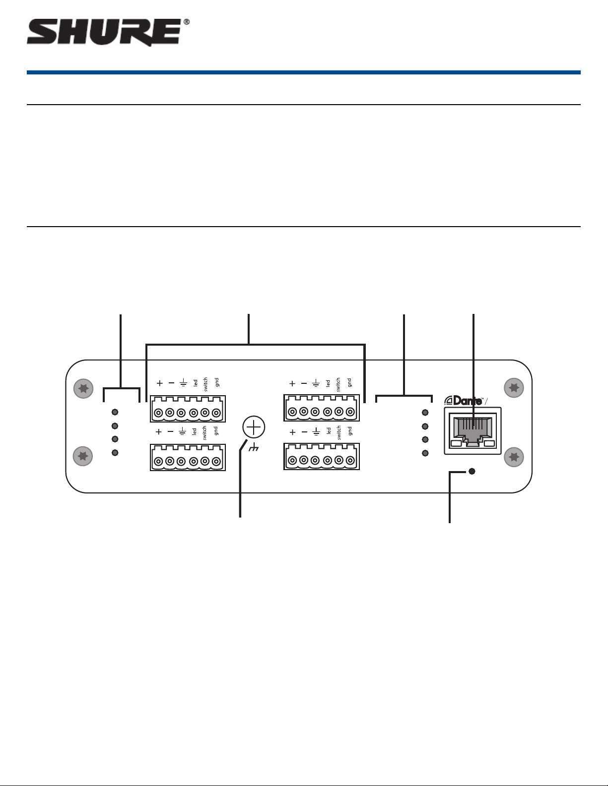
① Input Signal Clip Indicators
Each indicator corresponds to a single input channel. If the LED turns red, attenuate the level from the source device to prevent clipping at the input stage.
Analog and digital gain adjustments are made through the web application.
Audio Signal LevelLED State
less than -60 dBFSOff
-60 dBFS to -18 dBFSGreen
-18 dBFS to -6 dBFSYellow
-6 dBFS or moreRed
② Audio and Logic Inputs
Note: Logic connections are only featured on the block connector version
Block Inputs: Each input receives balanced audio and logic signals. Pin assignments are as follows:
switch
led
gnd
Audio +
Audio -
Audio ground
Logic Mute (sent from microphone)
Logic LED (received by microphone)
Logic ground
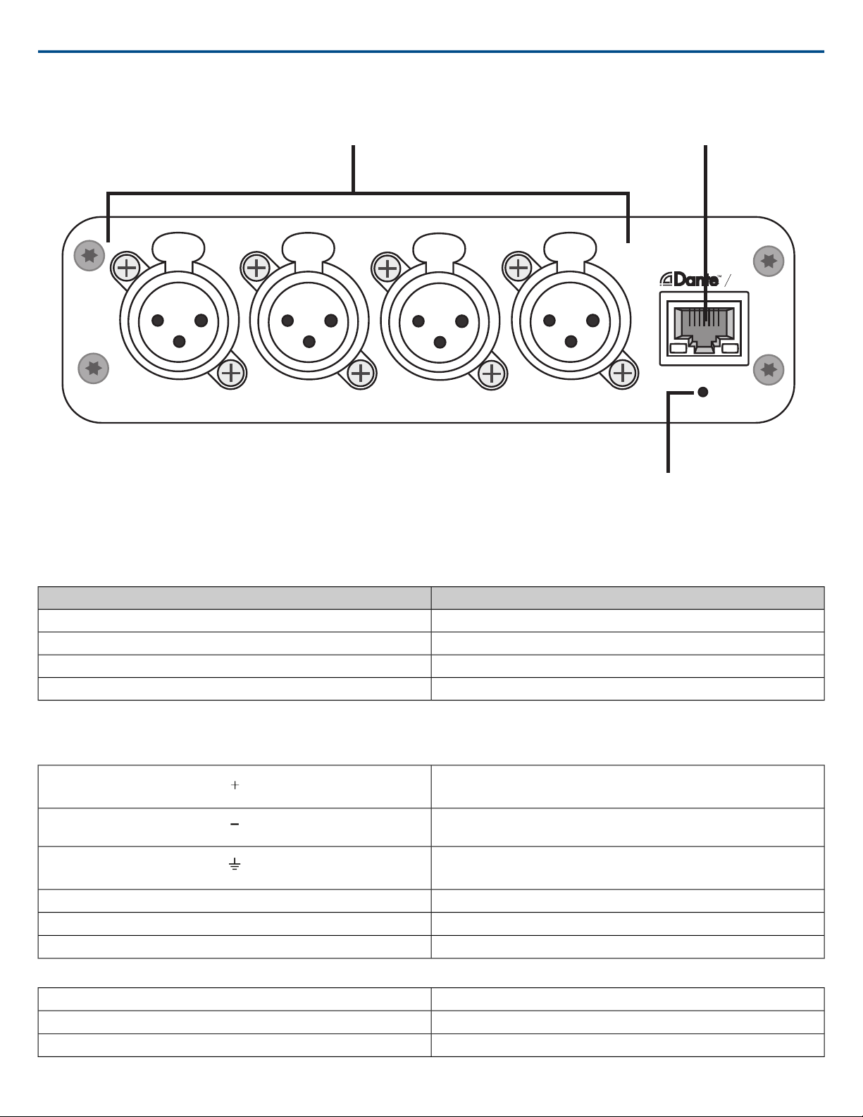
XLR Inputs: Each input receives a balanced audio signal. Pin assignments are as follows:
1
2
3
Ground
Positive
Negative
2017/10/302/28
Shure IncorporatedANI4IN Audio Network Interface
③ Chassis Ground Screw
Provides an optional connection for microphone shield wire to chassis ground
Note: only applies to block connector version
④ LED Indicators
Power:Power over Ethernet (PoE) present
Note: Use a PoE injector if your network switch does not supply PoE.
Network: Network connection active
Network Audio: Dante™ audio present on the network
Note: Error details are available in the event log in the web application.
Encryption: Not currently supported
ActivityLED Status
No active signalOff
Device is operating successfullyGreen
Error has occurred. See event log for details.Red
⑤ Dante Network Port
Connects to a network switch to send Dante™ audio, while receiving Power over Ethernet (PoE) and data from the control software. See the Dante and networking section for additional information.
⑥ Reset Button
Resets the device settings back to the factory default.
Power Over Ethernet (PoE)
Power Over Ethernet
This device requires PoE to operate. It is compatible with both Class 0 and Class 3 PoE sources.
Power over Ethernet is delivered in one of the following ways:
• A network switch that provides PoE
• A PoE injector device
Installation and Rack Mounting
Two mounting solutions are available for installing the Audio Network Interface:
CRT1 19" Rack Tray (optional accessory): Supports up to 3 devices; mountable in a rack or under a table
Single-unit Mounting Tray (included accessory):Supports a single device for mounting under a table
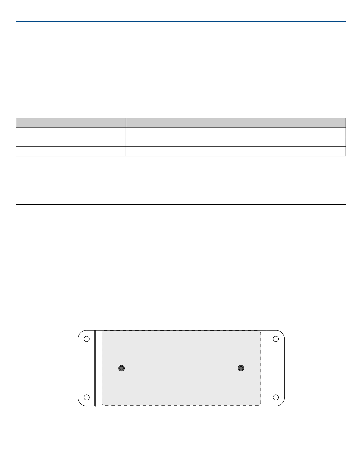
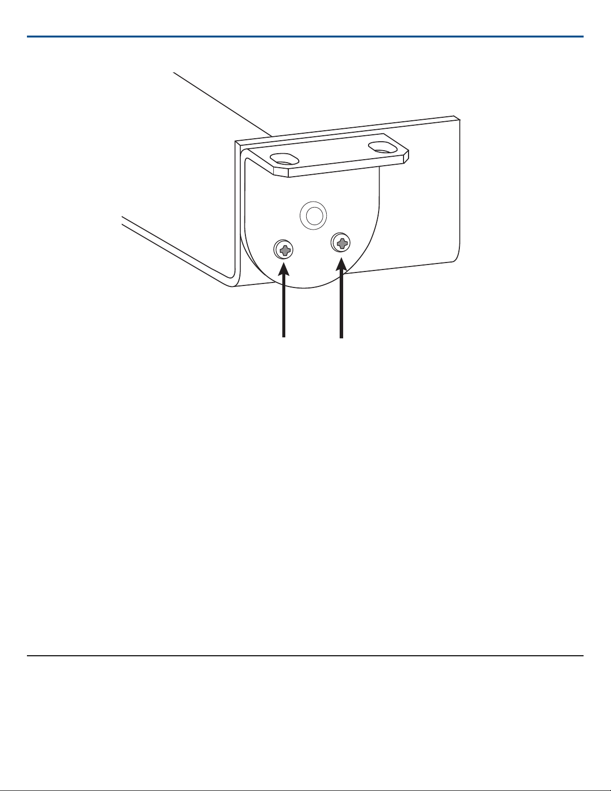
Securing the Devices
Use the included screws from the mounting hardware kit to secure the Audio Network Interfaces. Audio Network Interfacescan be mounted to face either direction.
Insert the screws from the bottom in the appropriate holes, according to the following diagrams:
Align the holes as shown for securing a single device in the single-unit mounting tray
3/282017/10/30
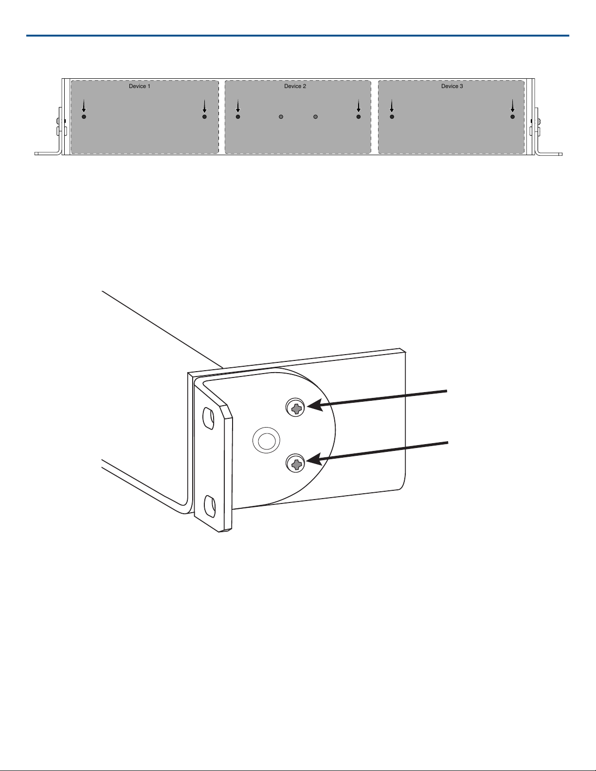
Device 1
Device 2
Device 3
Shure IncorporatedANI4IN Audio Network Interface
Align the holes as shown for securing up to three devices in the 19" rack tray.
Rack Ear Configuration
A combination of up to 3 Audio Network Interfaces can be mounted in a single 19-inch rack space. The adjustable rack ears support mounting in a standard
equipment rack or underneath a table.
Standard 19" Rack Mount
1. Align the ears with the mounting holes pointed forward.
2. Install the two screws that hold the ear to the tray as shown.
Under-table Mounting
1. Align the ears with the mounting holes pointed upward.
2. Install the two screws that hold the ear to the tray as shown.
2017/10/304/28
Shure IncorporatedANI4IN Audio Network Interface
Installing Underneath a Table
1. Hold the tray in the desired location under a table
2. Use a pencil to mark the location of the mounting holes on the table.
3. Drill 4 holes for the screws. The diameter of the holes in the tray are 7.1 mm.
4. Install the components into the tray
5. Install with 4 screws to secure the tray underneath the table
Reset
The reset button is located inside a small hole in the rear panel. Use a paperclip or other small tool to press the button.
There are two hardware reset functions:
Network reset (press button for 4-8 seconds)
Resets all Shure control and audio network IP settings to factory defaults
Full factory reset (press button for longer than 8 seconds)
Restores all network and web applicationsettings to the factory defaults.
Software Reset Options
To simply revert settings without a complete hardware reset, use one of the following options:
Reboot Device:In the web application (settings > factory reset), there is a Reboot De vicebutton, which simply power-cycles the device as if it were unplugged
from the network. All settings are retained when the device is rebooted.
Default Settings: To revert audio settings back to the factory configuration (excluding Device Name, IP Settings, and Passwords), select Load Preset and
choose the default settings preset.
Signal Flow and Connections
Setting up the Audio Network
Shure networked conferencing systemsare comprised of Microflex Advance microphones and network interfaces, which operate entirely on a Dante™ network.
Additional hardware, including network switches, computers, loudspeakers, and audio processors are described in the hardware component index.
Shure components shown in this diagram:
5/282017/10/30
Microflex Advance Microphones
reset
PoE
INPUT
reset
PoE
INPUT
sig/clip
power
reset
PoE
network
network audio
encryption
1
1
2
234
3
4
OUTPUT
sig/clip
power
reset
PoE
network
network audio
encryption
1
1
2
234
3
4
OUTPUT
ULXD4Q
Digital Wireless Receiver
push
control
ENTER
EXIT
SCAN
power
RF
AB
OL
OL
gainaudio
RF
AB
OL
OL
gainaudio
RF
AB
OL
OL
gainaudio
RF
AB
OL
OL
gainaudio
RX1 RX2 RX3 RX4
IR
sync
sync sync sync
SEL
SEL
ULXD4Q
Digital Wireless Receiver
push
control
ENTER
EXIT
SCAN
power
RF
AB
OL
OL
gainaudio
RF
AB
OL
OL
gainaudio
RF
AB
OL
OL
gainaudio
RF
AB
OL
OL
gainaudio
RX1 RX2 RX3 RX4
IR
sync
sync sync sync
SEL
SEL
ULXD1
ULXD1
on
ULXD2
on
ULXD2
ULXD4Q
Digital Wireless Receiver
push
control
ENTER
EXIT
SCAN
power
RF
AB
OL
OL
gainaudio
RF
AB
OL
OL
gainaudio
RF
AB
OL
OL
gainaudio
RF
AB
OL
OL
gainaudio
RX1 RX2 RX3 RX4
IR
sync
sync sync sync
SEL
SEL
ULXD4Q
Digital Wireless Receiver
push
control
ENTER
EXIT
SCAN
power
RF
AB
OL
OL
gainaudio
RF
AB
OL
OL
gainaudio
RF
AB
OL
OL
gainaudio
RF
AB
OL
OL
gainaudio
RX1 RX2 RX3 RX4
IR
sync
sync sync sync
SEL
SEL
ULXD1
ULXD1
on
ULXD2
on
ULXD2
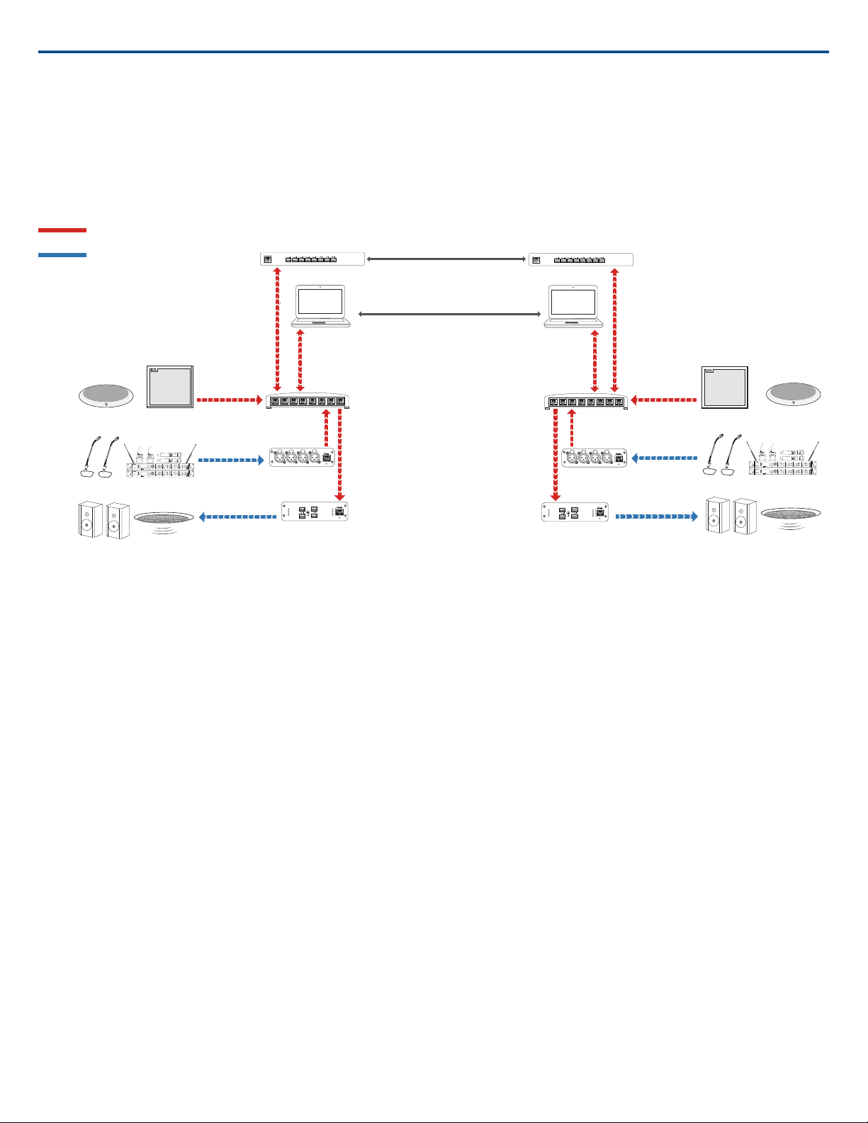
Dante
Analog
Microflex Advance microphones
Analog microphones
Loudspeakers
Option 1 (VOIP/TELCO)
Option 2 (Internet/DVS)
Near end
Far end
Network switch
Network interface (ANI4IN)
Network interface (ANI4OUT)
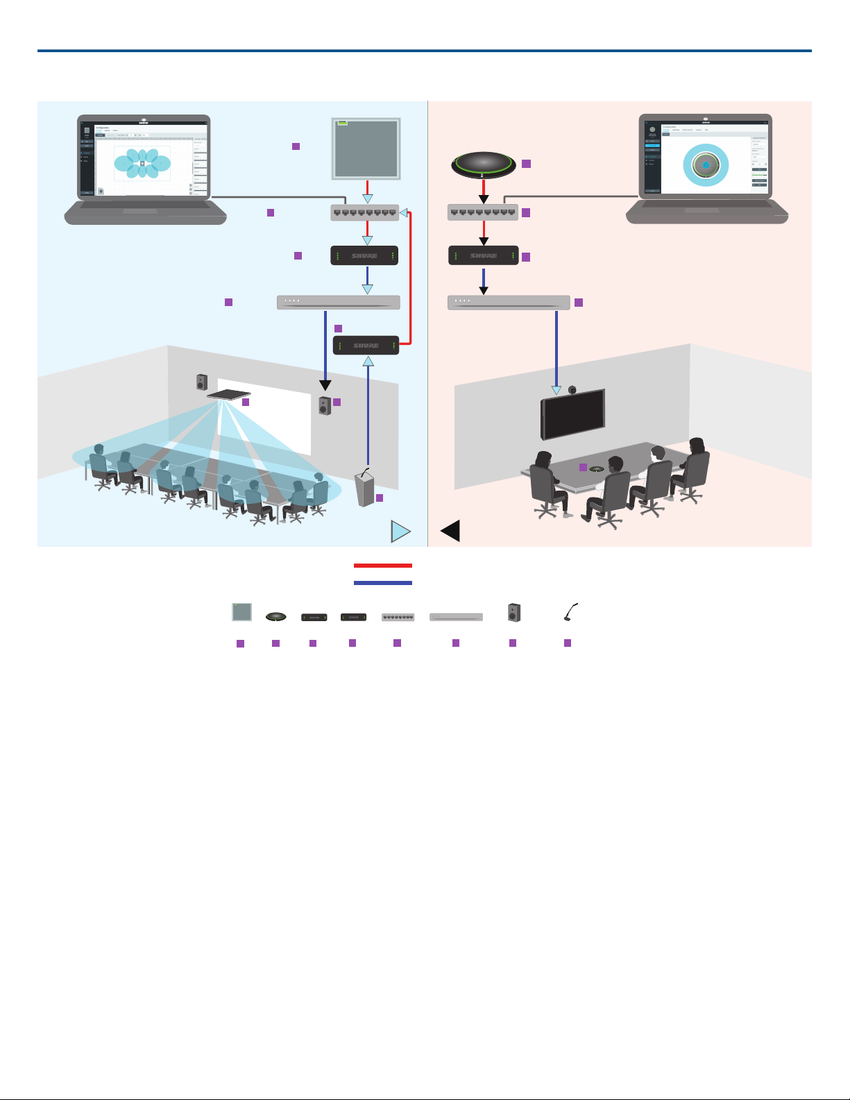
The MXA910 and MXA310 are equipped with Dante outputs, and connect directly to a network switch.
Audio Network Interfaces
The interfaces are used to connect analog devices such as loudspeakers and analog microphones to the network.
ANI4IN: Converts 4 analog signals (separate XLR and block connector models available) into Dante™ digital audio signals.
ANI4OUT:Converts 4 channels of Dante™ audio from the network into analog signals.
Shure IncorporatedANI4IN Audio Network Interface
This diagram shows the entire signal path through a networked conference system. Signals from the near end and far end are exchanged through an audio
processor connected to a phone system, or through a computer connected to the internet. Analog microphones connect to the network through the Shure ANI4IN,
while loudspeakers connect through the Shure ANI4OUT.
2017/10/306/28
sig/clip
power
network
network audio
encryption
1
2
3
4
sig/clip
power
network
network audio
encryption
1
2
3
4
sig/clip
power
network
network audio
encryption
1
2
3
4
ROOM A SIGNAL
ROOM B SIGNAL
sig/clip
power
network
network audio
encryption
1
2
3
4
sig/clip
power
network
network audio
encryption
1
2
3
4
MXA910
MXA910
MXA310
MXA310
ANI4IN
ANI4IN
ANI4OUT
ANI4OUT
ANI4OUT
NETWORK SWITCH
NETWORK SWITCH NETWORK SWITCH
VIDEO CODEC
VIDEO CODEC
VIDEO CODEC
LOUDSPEAKERS
ANALOG MICROPHONES
1
1
1
2
2
2
3
3
4
4
4
5
5
5
6
6
6
7
7
8
8
Dante Signals
Analog Signals
Shure IncorporatedANI4IN Audio Network Interface
This diagram shows Microflex Advance components in context, with two rooms communicating through video codecs.
Controlling Hardware and Audio Over the Network
Audio and hardware settings are managed through a computer connected to the same network.
Shure Hardware and Audio
Each Microflex Advance component has a web applicationwhich provides mixing and configuration tools to optimize sound quality.
Expanded Control for Analog Devices
Analog devices that are connected to the network through a Shure network interface (ANI4IN/ANI4OUT) benefit from additional remote control: Volume levels,
equalization, and signal routing are managed through the web application. For example, adjusting loudspeaker volume or muting a wired microphone, which
would normally be done from the hardware, can now be controlled remotely over the network.
Dante™ Signal Routing
Signal routing between devices is managed through Dante Controller software, provided by Audinate™ .
7/282017/10/30
Connections and Signal Flow
sig/clip
power
reset
PoE
network
network audio
encryption
1
1
2
2
3
4
3
4
INPUT
ULXD4
Digital Wireless Receiver
push
control
ENTER
EXIT
SCAN
RF
A B
OL
OL
gain poweraudio
IR
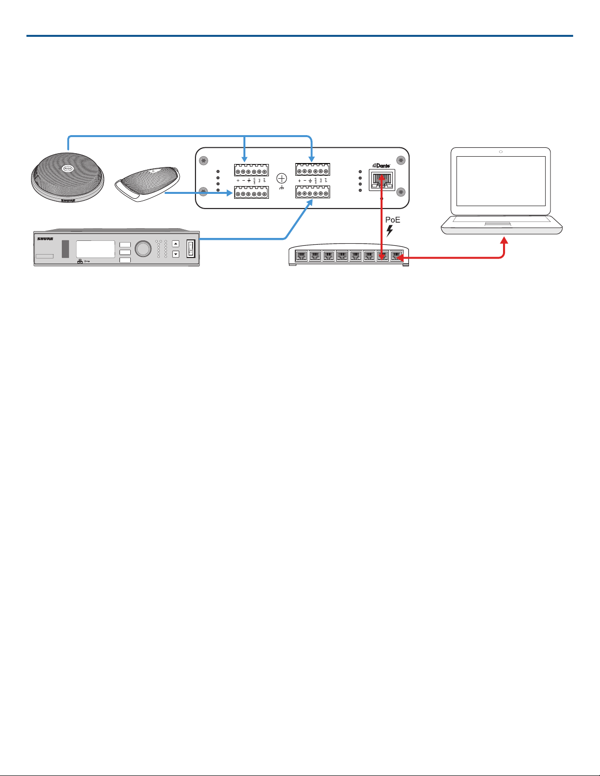
① MX396
② MX392
③ ULX-D Receiver
④ Network Switch
⑤ Computer
Shure IncorporatedANI4IN Audio Network Interface
① MX396 (Dual-element)
In addition to running the audio signals, this boundary microphone features three additional wire leads for logic connections. This allows the switch on the microphone
to send a logic mute signal to other equipment on the network, and to receive a logic LED control signal.
② MX392
In addition to running the audio signal, this boundary microphone features three additional wire leads for logic connections. This allows the switch on the microphone
to send a logic mute signal to other equipment on the network, and to receive a logic LED control signal.
③ ULX-D Receiver
Wireless microphones connect to the network interface through the balanced analog outputs on the receiver.
④ Network Switch
Provides connectivity between the Dante™ audio network and the computer that controls signal processing and routing.
⑤ Computer
A computer or tablet running the web application provides independent gain control for each connected device.
Input: Analog (4 XLR or Block Connectors)
Each Audio Network Interface has 4 analog inputs with variable analog gain for line, auxiliary, and microphone-level signals. Examples of devices to connect to
the network with the Audio Network Interface:
• Wireless microphone systems
• Wired installed microphones (logic functions supported by block connector model)
• Computers or mobile devices used for presentations
• Other playback devices
Output: Dante™ Digital Audio
Connect the Dante™ output to a network switch with a network cable. A single network cable delivers all 4 channels of audio onto the network, and carries
Power over Ethernet (PoE) to power the device. Use Dante™ Controller to route audio channels from the Audio Network Interface to the appropriate network
destination. Any of the signals may be routed to multiple destinations, to provide local reinforcement while simultaneously delivering audio to the far end.
Summing
The Audio Network Interface provides channel summing to combine input signals and send them over a single Dante™ channel. This makes it possible to send
all channels to a device with a limited amount of Dante™ receiver channels. Mixer functionality does not change; audio channels are simply sent as one combined
signal.
Note:When summing is enabled, a limiter is activated to prevent signal overloading. The limiter never applies to the direct outputs, and only affects the summed
signal.
To enable, select one of the summing options in the toolbar at the top of the mixer in the channels tab.
2017/10/308/28
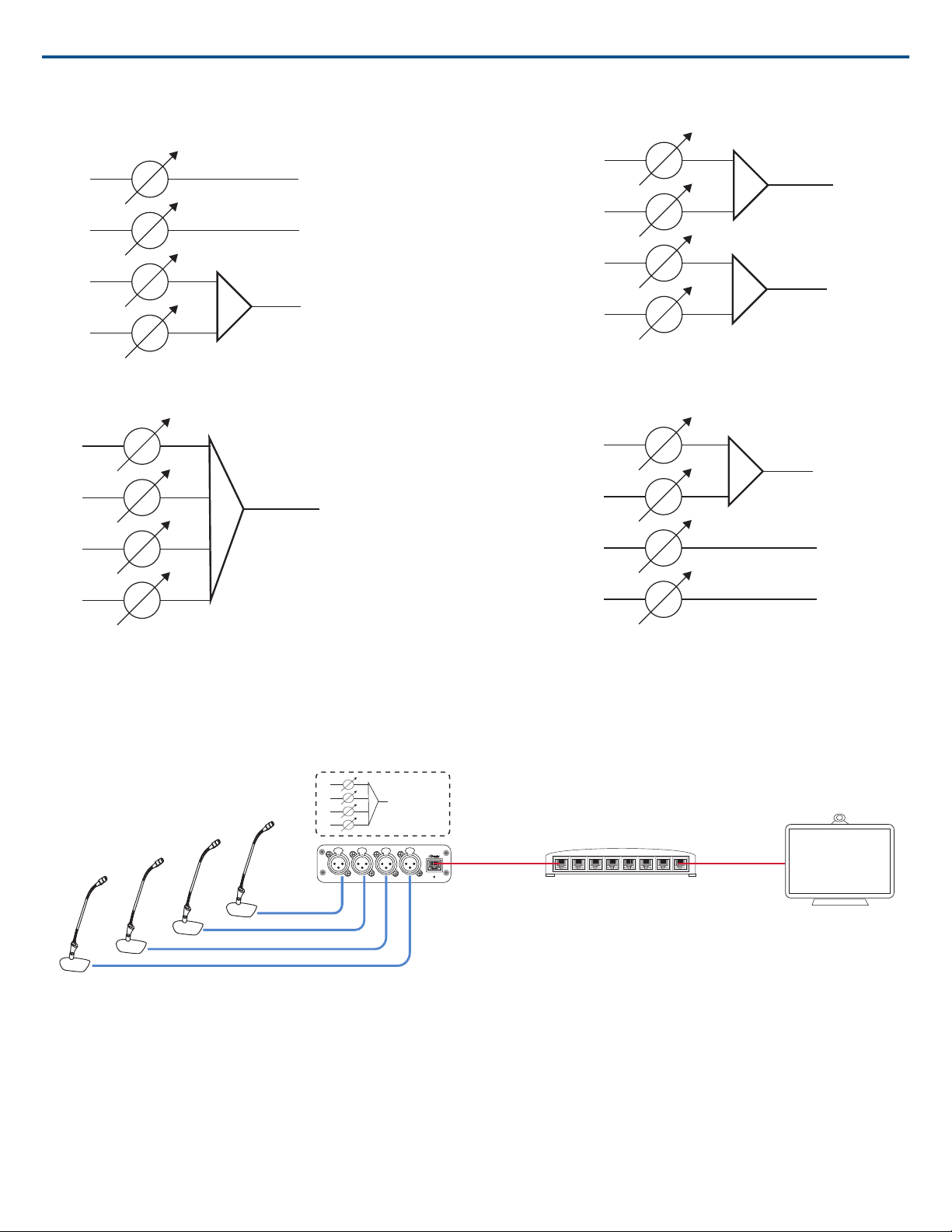
1 + 2 + 3 + 4
1
2
3
4
3
4
1 +2
1
2
3
4
2
1
3 + 4
1
2
3
4
1 + 2
3 + 4
1
2
3
4
reset
PoE
INPUT
1 + 2 + 3 + 4
1
2
3
4
Shure IncorporatedANI4IN Audio Network Interface
Example Scenario
A common application that requires summing is a video conference where there are multiple microphones. When a device (a computer running conferencing
software and Dante™ Virtual Soundcard, for example) only supports 1 or 2 Dante™ receiver channels, the Audio Network Interface combines the input signals
to transmit as a single Dante™ channel.
① Summed analog audio channels
When the 4 analog audio channels are summed, each of the Dante™ transmit channels includes all of the input signals.
② Single Dante audio channel
One Dante™ signal is sent over the network, which contains all 4 summed channels.
③ Connection to computer
A computer that is running limited number of Dante™ channels with Dante™ Virtual Soundcard, receives all audio on a single channel. This audio is sent to
the far end.
9/282017/10/30
 Loading...