

Page 1
AD4Q
Digital Quad Receiver
AD4Q Axient Digital Quad Channel Receiver User Guide
Version: 8 (2020-A)
Page 2

Table of Contents
AD4QDigital Quad Receiver 4
IMPORTANT SAFETY INSTRUCTIONS 4
Australia Warning for Wireless 5
AD4Q Axient Digital Four-Channel Wireless Receiver 5
Features 5
Included Components 6
Mounting Instructions 6
Hardware 7
Receiver Front Panel 7
Receiver Back Panel 8
Menus and Configuration 10
Accessing the Device Configuration Menu or Channel
Menus 10
Home Screen 11
Screen Icons 11
Device Configuration Menu 12
AD4D Device Configuration Parameters 13
Channel Menu Parameters 17
Radio Frequency (RF) Settings 19
Setting the RF Tuning Band 19
IR Sync 19
Setting the Frequency Manually 20
Channel Scan and Group Scan 20
Requesting a New Frequency from a Spectrum Manager 2
1
Transmission Modes 21
Assigning Transmitters to Transmitter Slots 22
Interference Management 23
Channel Quality Meter 23
Shure Incorporated
Frequency Diversity 24
Quadversity 24
Antenna Bias 25
RF Cascade Ports 25
Firmware 25
Audio Settings 26
Adjusting Channel Gain and Audio Output 26
Tone Generator 27
Headphone Monitoring 27
System Gain 28
Networking 28
Networking Receivers 28
Network Browser 29
Network Troubleshooting 30
Operation 30
Assigning a Device ID 30
Assigning a Channel Name 30
Locking and Unlocking the Controls 31
Display Screen Options 31
Saving Receiver Settings as User Presets 31
Programming Transmitters Using IR Presets 31
Encryption 32
Cooling Fan 32
Restoring the Receiver to Factory Settings 33
Troubleshooting 33
Power 33
Gain 33
Cables 33
Interface Locks 33
Encryption Mismatch 33
Firmware Mismatch 34
2/40
Page 3

Shure Incorporated
Radio Frequency (RF) 34
Specifications 35
Tables and Diagrams 38
Receiver Frequency Bands 39
Certifications 40
3/40
Page 4
AD4Q Digital Quad Receiver
IMPORTANT SAFETY INSTRUCTIONS
1.
READ these instructions.
2.
KEEP these instructions.
3.
HEED all warnings.
4.
FOLLOW all instructions.
5.
DO NOT use this apparatus near water.
6.
CLEAN ONLY with dry cloth.
7.
DO NOT block any ventilation openings. Allow sufficient distances for adequate ventilation and install in accordance
with the manufacturer’s instructions.
8.
DO NOT install near any heat sources such as open flames, radiators, heat registers, stoves, or other apparatus (in
cluding amplifiers) that produce heat. Do not place any open flame sources on the product.
9.
DO NOT defeat the safety purpose of the polarized or grounding type plug. A polarized plug has two blades with one
wider than the other. A grounding type plug has two blades and a third grounding prong. The wider blade or the third
prong are provided for your safety. If the provided plug does not fit into your outlet, consult an electrician for replace
ment of the obsolete outlet.
10.
PROTECT the power cord from being walked on or pinched, particularly at plugs, convenience receptacles, and the
point where they exit from the apparatus.
11.
ONLY USE attachments/accessories specified by the manufacturer.
12.
USE only with a cart, stand, tripod, bracket, or table specified by the manufacturer, or sold with the apparatus. When a
cart is used, use caution when moving the cart/apparatus combination to avoid injury from tip-over.
Shure Incorporated
13.
UNPLUG this apparatus during lightning storms or when unused for long periods of time.
14.
REFER all servicing to qualified service personnel. Servicing is required when the apparatus has been damaged in any
way, such as power supply cord or plug is damaged, liquid has been spilled or objects have fallen into the apparatus,
the apparatus has been exposed to rain or moisture, does not operate normally, or has been dropped.
15.
DO NOT expose the apparatus to dripping and splashing. DO NOT put objects filled with liquids, such as vases, on the
apparatus.
16.
The MAINS plug or an appliance coupler shall remain readily operable.
17.
The airborne noise of the Apparatus does not exceed 70dB (A).
18.
Apparatus with CLASS I construction shall be connected to a MAINS socket outlet with a protective earthing connec
tion.
19.
To reduce the risk of fire or electric shock, do not expose this apparatus to rain or moisture.
20.
Do not attempt to modify this product. Doing so could result in personal injury and/or product failure.
21.
Operate this product within its specified operating temperature range.
4/40
Page 5
Shure Incorporated
WARNING: Voltages in this equipment are hazardous to life. No user-serviceable parts inside. Refer all servicing to qualified
service personnel. The safety certifications do not apply when the operating voltage is changed from the factory setting.
Australia Warning for Wireless
This device operates under an ACMA class licence and must comply with all the conditions of that licence including operating
frequencies. Before 31 December 2014, this device will comply if it is operated in the 520-820 MHz frequency band.
WARNING: After 31 December 2014, in order to comply, this device must not be operated in the 694-820 MHz band.
AD4Q Axient Digital Four-Channel Wireless Receiver
The AD4Q Axient Digital FourChannel Wireless Receiver sets a new standard in transparent digital audio and maximum spec
tral efficiency. Groundbreaking performance features include wide tuning, low latency, High Density (HD) mode, and Quadver
™
sity , ensuring solid performance in the most challenging RF environments. Networked control, AES3 and Dante output, and
signal routing options bring a new level of management and flexibility to your entire workflow. Compatible with all Axient Digital
transmitters.
Features
Audio
•
60 dB of gain adjustment offers compatibility with a wide range of input sources
•
•
•
•
•
I/O
•
•
•
•
•
•
™
Dante networking for quick and easy channel management
Dante Browse feature for headphone monitoring of all Dante channels, including third party components
AES 256 encryption to protect audio channels
Automatic limiter function protects against signal clipping, allowing for higher gain settings and preventing unexpected sig
nal peaks
Front panel connection for headphones with adjustable volume
Four transformer-balanced XLR outputs (outputs 3 and 4 switchable AES3 digital)
Four transformer-balanced 1/4'' outputs
Two Dante-enabled Ethernet ports, Two network control Ethernet ports with PoE
◦
Split-Redundant mode: two ports of Ethernet, two ports of Dante
◦
Switched mode: four ports of Ethernet, Four ports of Dante
Locking AC power connection
AC power cascade to additional components
Optional DC module available to support redundant power
RF
•
True digital diversity reception per channel
•
Quadversity mode for enhanced coverage
•
Up to 210 MHz of tuning range
•
Channel Quality meter displays signal-to-noise ratio of RF signal
•
Frequency diversity with selection or combining modes for transmitters
5/40
Page 6
Shure Incorporated
•
Antenna cascade for one additional receiver
•
Preprogrammed group and channel maps with options to create custom groups
•
Search for open frequencies via receiver using group and channel scan
•
Perform full bandwidth scan for frequency coordination via Wireless Workbench
•
Register up to eight transmitters to one receiver channel
•
High Density transmission mode enables up to 47 active transmitters in one 6 MHz TV channel (up to 63 in one 8 MHz TV
channel)
Network Control
•
Wireless Workbench control software
•
ShurePlus Channels mobile device control
•
Console integration
•
Control systems support
™
®
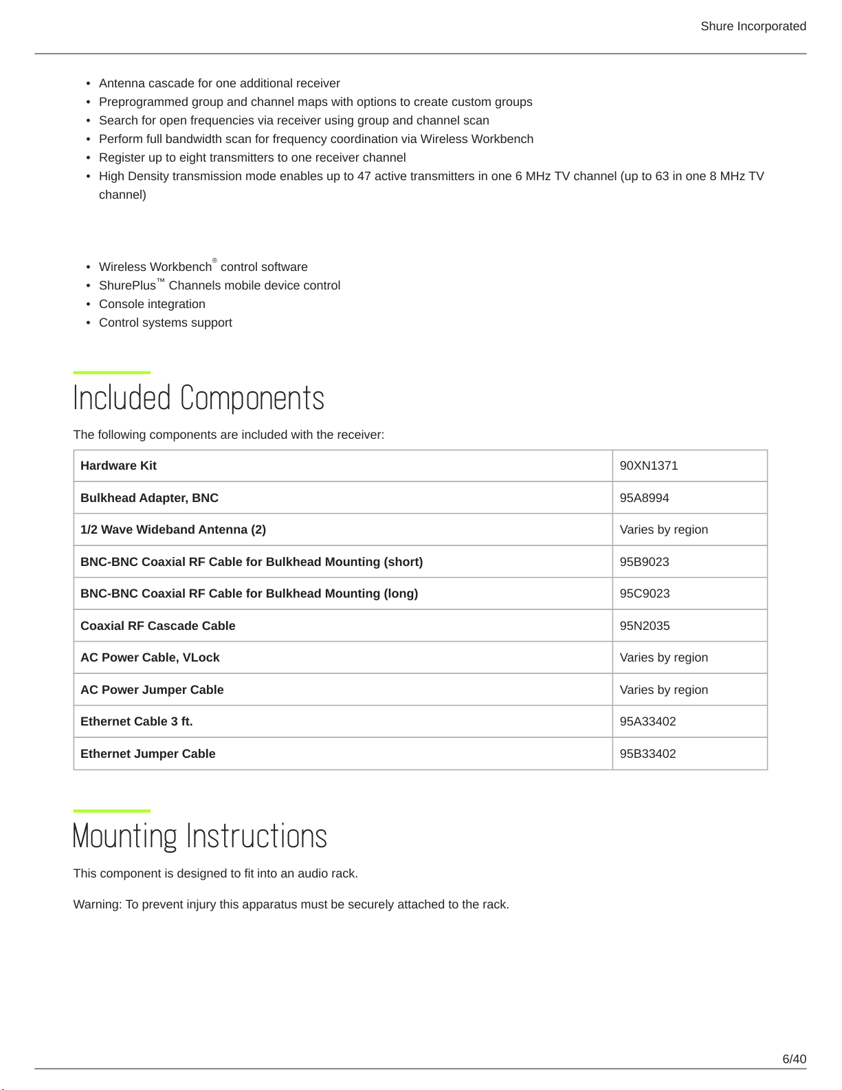
Included Components
The following components are included with the receiver:
Hardware Kit 90XN1371
Bulkhead Adapter, BNC 95A8994
1/2 Wave Wideband Antenna (2) Varies by region
BNC-BNC Coaxial RF Cable for Bulkhead Mounting (short) 95B9023
BNC-BNC Coaxial RF Cable for Bulkhead Mounting (long) 95C9023
Coaxial RF Cascade Cable 95N2035
AC Power Cable, VLock Varies by region
AC Power Jumper Cable Varies by region
Ethernet Cable 3 ft. 95A33402
Ethernet Jumper Cable 95B33402
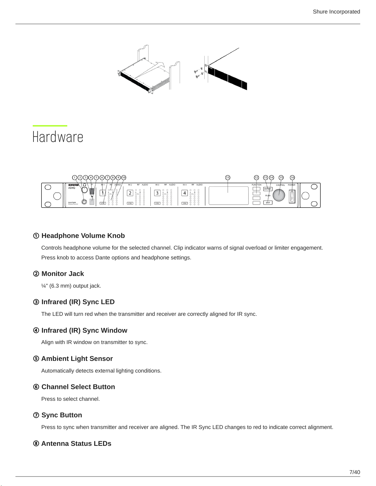
Mounting Instructions
This component is designed to fit into an audio rack.
Warning: To prevent injury this apparatus must be securely attached to the rack.
6/40
Page 7
Hardware
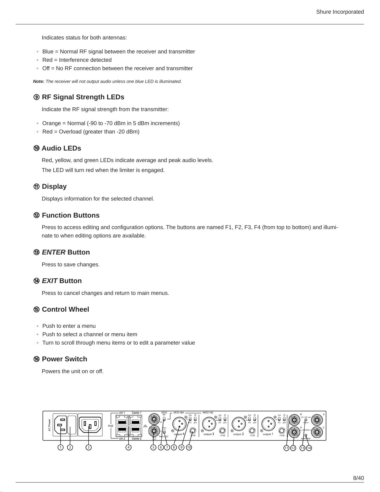
Receiver Front Panel
Shure Incorporated
① Headphone Volume Knob
Controls headphone volume for the selected channel. Clip indicator warns of signal overload or limiter engagement.
Press knob to access Dante options and headphone settings.
② Monitor Jack
¼" (6.3 mm) output jack.
③ Infrared (IR) Sync LED
The LED will turn red when the transmitter and receiver are correctly aligned for IR sync.
④ Infrared (IR) Sync Window
Align with IR window on transmitter to sync.
⑤ Ambient Light Sensor
Automatically detects external lighting conditions.
⑥ Channel Select Button
Press to select channel.
⑦ Sync Button
Press to sync when transmitter and receiver are aligned. The IR Sync LED changes to red to indicate correct alignment.
⑧ Antenna Status LEDs
7/40
Page 8
Indicates status for both antennas:
◦
Blue = Normal RF signal between the receiver and transmitter
◦
Red = Interference detected
◦
Off = No RF connection between the receiver and transmitter
Note: The receiver will not output audio unless one blue LED is illuminated.
⑨ RF Signal Strength LEDs
Indicate the RF signal strength from the transmitter:
◦
Orange = Normal (-90 to -70 dBm in 5 dBm increments)
◦
Red = Overload (greater than -20 dBm)
⑩ Audio LEDs
Red, yellow, and green LEDs indicate average and peak audio levels.
The LED will turn red when the limiter is engaged.
⑪ Display
Shure Incorporated
Displays information for the selected channel.
⑫ Function Buttons
Press to access editing and configuration options. The buttons are named F1, F2, F3, F4 (from top to bottom) and illumi
nate to when editing options are available.
⑬ ENTER Button
Press to save changes.
⑭ EXIT Button
Press to cancel changes and return to main menus.
⑮ Control Wheel
◦
Push to enter a menu
◦
Push to select a channel or menu item
◦
Turn to scroll through menu items or to edit a parameter value
⑯ Power Switch
Powers the unit on or off.
Receiver Back Panel
8/40
Page 9
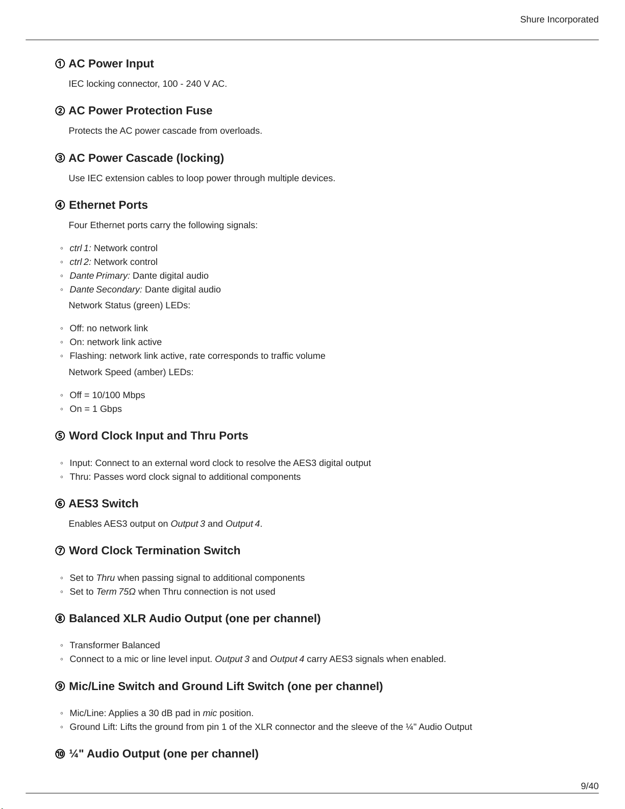
① AC Power Input
IEC locking connector, 100 - 240 V AC.
② AC Power Protection Fuse
Protects the AC power cascade from overloads.
③ AC Power Cascade (locking)
Use IEC extension cables to loop power through multiple devices.
④ Ethernet Ports
Four Ethernet ports carry the following signals:
◦
ctrl 1: Network control
◦
ctrl 2: Network control
◦
Dante Primary: Dante digital audio
◦
Dante Secondary: Dante digital audio
Network Status (green) LEDs:
Shure Incorporated
◦
Off: no network link
◦
On: network link active
◦
Flashing: network link active, rate corresponds to traffic volume
Network Speed (amber) LEDs:
◦
Off = 10/100 Mbps
◦
On = 1 Gbps
⑤ Word Clock Input and Thru Ports
◦
Input: Connect to an external word clock to resolve the AES3 digital output
◦
Thru: Passes word clock signal to additional components
⑥ AES3 Switch
Enables AES3 output on Output 3 and Output 4.
⑦ Word Clock Termination Switch
◦
Set to Thru when passing signal to additional components
◦
Set to Term 75Ω when Thru connection is not used
⑧ Balanced XLR Audio Output (one per channel)
◦
Transformer Balanced
◦
Connect to a mic or line level input. Output 3 and Output 4 carry AES3 signals when enabled.
⑨ Mic/Line Switch and Ground Lift Switch (one per channel)
◦
Mic/Line: Applies a 30 dB pad in mic position.
◦
Ground Lift: Lifts the ground from pin 1 of the XLR connector and the sleeve of the ¼" Audio Output
⑩ ¼" Audio Output (one per channel)
9/40
Page 10

Shure Incorporated
Transformer Balanced
⑪ Coaxial inputs from Antenna A and Antenna B
RF Connection for Antenna A and Antenna B.
⑫ RF Cascade Connectors C and D
Passes the RF signal from Antenna A and Antenna B to one additional receiver. In Quadversity mode, use these connectors
for additional antenna inputs.
⑬ Antenna Bias Indicator LED
◦
Green: Antenna bias enabled
◦
Red: Antenna fault
◦
Off: Antenna bias disabled
⑭ Quadversity Indicator LED
Illuminates when the receiver is configured for Quadversity mode.
Menus and Configuration
The receiver uses a two-tier menu structure to support multiple channels in a single rack space:
•
Device Configuration Menu: Items in this menu affect the overall performance of the receiver and apply to all channels
globally
•
Channel Configuration Menus: Each channel has its own menu allowing for independent channel configuration
Accessing the Device Configuration Menu or Channel Menus
From the home screen, use the following methods to access the Device Configuration menu or to enter one of the channel
menus.
•
To enter the Device Configuration menu, press the control wheel
•
To enter a Channel menu, select the channel number, and then press the control wheel to access the menu
10/40
Page 11
Shure Incorporated
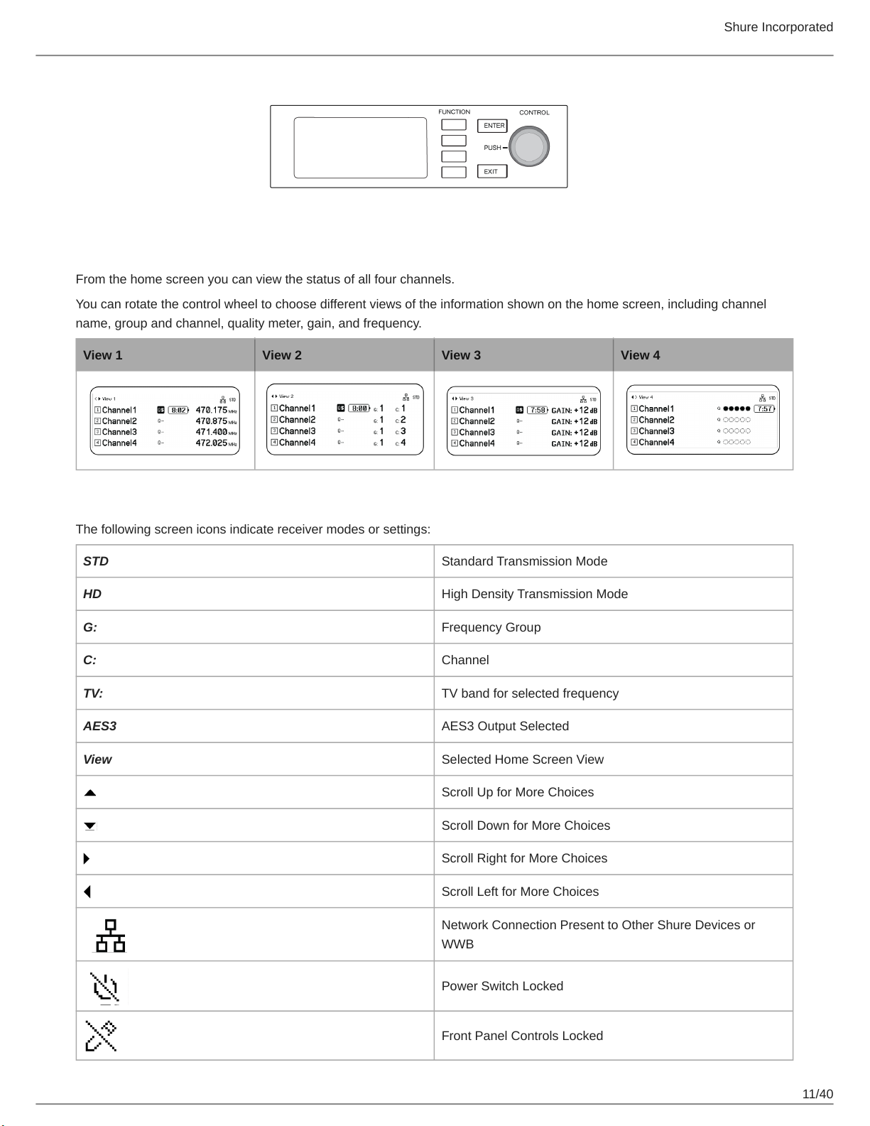
Home Screen
From the home screen you can view the status of all four channels.
You can rotate the control wheel to choose different views of the information shown on the home screen, including channel
name, group and channel, quality meter, gain, and frequency.
View 1 View 2 View 3 View 4
Screen Icons
The following screen icons indicate receiver modes or settings:
STD Standard Transmission Mode
HD High Density Transmission Mode
G: Frequency Group
C: Channel
TV: TV band for selected frequency
AES3 AES3 Output Selected
View Selected Home Screen View
Scroll Up for More Choices
Scroll Down for More Choices
Scroll Right for More Choices
Scroll Left for More Choices
Network Connection Present to Other Shure Devices or
WWB
Power Switch Locked
Front Panel Controls Locked
11/40
Page 12
Shure Incorporated
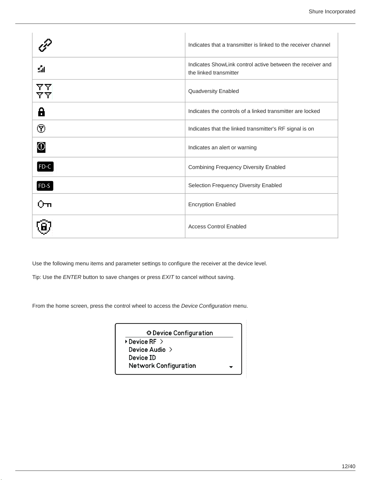
Indicates that a transmitter is linked to the receiver channel
Indicates ShowLink control active between the receiver and
the linked transmitter
Quadversity Enabled
Indicates the controls of a linked transmitter are locked
Indicates that the linked transmitter's RF signal is on
Indicates an alert or warning
Combining Frequency Diversity Enabled
Selection Frequency Diversity Enabled
Encryption Enabled
Access Control Enabled
Device Configuration Menu
Use the following menu items and parameter settings to configure the receiver at the device level.
Tip: Use the ENTER button to save changes or press EXIT to cancel without saving.
Device Configuration Menu Screen
From the home screen, press the control wheel to access the Device Configuration menu.
12/40
Page 13

Device Configuration Menu Map
Shure Incorporated
AD4D Device Configuration Parameters
Device RF
RF Band
Select the tuning band for the receiver.
Encryption
Enables encryption of the RF signal.
Transmission Mode
Select Standard or High Density transmitter spacing.
Quadverstiy
Enable Quadversity mode to configure RF ports to accept four antennas.
Custom Groups
Configure, edit, or load custom frequency groups.
13/40
Page 14

Antenna Bias
Enable antenna bias for active RF antennas.
TV Format
Adjust TV bandwidth to match regional standards.
Device Audio
AES3 Audio
Configure AES3 audio parameters.
Dante Names
View, edit, and copy names for networked Dante components.
Device ID
Device ID
Shure Incorporated
Use the control wheel to assign or edit an ID.
Network Configuration
Configure IP, network, and Dante settings.
Setup
Configure Ethernet ports and IP settings.
Access
View the status of Access Control (Enabled or Disabled). Use Wireless Workbench or other Shure control software to en
able or disable Access Control.
Network Browser
Use the Network Browser utility to view Shure devices on the network.
Show
Display all devices on the network.
Flash All
Flash the front panel LED of all devices on the network to verify connectivity.
F.W. Version
Displays the installed firmware version of the selected network component.
Locks
Power Switch
◦
Locked
◦
Unlocked
14/40
Page 15

Front Panel
◦
Locked
◦
Unlocked
Fan
Fan Mode
◦
Auto: The fan will automatically turn on if the receiver temperature rises
◦
On: The fan will run continuously to offer maximum cooling in warm environments
Temperature
Displays internal receiver temperature.
Display
Brightness
Adjust the brightness of the display.
Shure Incorporated
Invert
Inverts the color of the display.
Display Sleep
Offers options to turn off display and front panel illumination after 10, 30, or 60 seconds.
Tip:
Press any front panel control to interrupt Display Sleep.
DC Module Status (optional)
Displays operational status of the DC Module (if installed).
Tx Firmware Update
Align transmitter IR window and select to update transmitter firmware.
User Presets
Create and manage user presets.
•
Restore User Preset: Load existing preset
•
Save User Preset: Save the current settings as a preset
•
Delete User Preset: Delete a preset
Factory Reset
Restores all receiver parameters to factory settings.
About
Provides a detailed list of build specifications and vital statistics for the receiver.
15/40
Page 16

Shure Incorporated
Channel Menu
Use the following menus and parameters to configure the receiver channels.
Tip: Use the channel selection buttons to navigate between adjacent channels when configuring menu parameters. Use the
ENTER button to save changes or press EXIT to cancel without saving.
Channel Menu Home Screen
The Channel Menu Home Screen allows you to view the settings for a selected channel and details of transmitters linked to
that channel. Select a channel number to access the menu.
You can adjust gain, group, channel, and frequency by using the EDIT function button.
Channel Menu
Use the Channel Menu to select and edit menu parameters. Press the Control Wheel to access the Channel Menu from the
Channel Menu Home Screen.
16/40
Page 17

Channel Menu Map
Shure Incorporated
Channel Menu Parameters
New Frequency
Press ENTER to deploy a new frequency when using a spectrum manager as a frequency server.
Note: This menu option will not be shown if you don't have a frequency server assigned to the receiver.
Audio
Gain/Mute
Adjusts the receiver gain.
◦
Gain: Adjust the gain in 1 dB increments
◦
Output: Select On or Mute for the receiver audio output
Switch Status
Displays the switch position of the ground lift and level switches.
System Gain
View and calculate all gain stages in the signal chain, including input pads, mic offset, and receiver gain.
Tone Generator
Provides a continuous audio signal tone for testing and troubleshooting.
Meter Overload Hold
Enable Overload Hold to capture signal peaks.
17/40
Page 18

Radio
G: (Group)
Assign a frequency group.
C: (Channel)
Assign a channel.
Frequency
Manually select a frequency.
TV
Displays the TV band for the selected frequency.
Channel Name
Channel Name
Shure Incorporated
Use the control wheel to assign or edit the channel name.
Channel Scan
Finds available channels within the selected group:
•
Find Next: Selects the nearest available channel
•
Find Best: Selects the channels with the best RF noise floor
Group Scan
Scans the selected group to find all available channels.
Transmitters(s)
Transmitter Slots
Use the control wheel to assign and view transmitter slots.
ACTIVATE (ADX transmitters linked to ShowLink access point)
Choose a transmitter with the control wheel, and then press ACTIVATE pass RF and RF mute all other transmitters.
FLASH (ADX transmitters linked to ShowLink access point)
Flashes the display to of a transmitter linked to the receiver.
UNLINK
Removes a transmitter from the selected slot.
SYNC:
Assigns a transmitter to the selected slot when SYNC is pressed.
Transmitter Details
Displays build details and vital statistics for the selected transmitter.
18/40
Page 19

Shure Incorporated
IR Presets
Select and edit transmitter parameters so they will automatically be set during an IR sync.
Advanced
Interference Management
Select interference detection setting for the channel.
Frequency Diversity
Configure frequency diversity for handheld or bodypack transmitters.
Talk Switch/Output Routing
Set receiver output signal routing options for talk switch control from a transmitter. For more information about using a talk
switch with an Axient Digital transmitter, see the talk switch user guide.
Radio Frequency (RF) Settings
Setting the RF Tuning Band
The receiver offers selectable tuning bands to maximize the use of locally available spectrum.
1.
From the Device Configuration menu: Device RF > RF Band
2.
Press the control wheel to enable editing, and then select an RF band.
3.
Press ENTER to save.
Note: After setting the RF band, re-sync any transmitters that are linked to the receiver.
IR Sync
Use IR Sync to form an audio channel between the transmitter and receiver.
Note: The receiver band must match the band of the transmitter.
1.
Select a receiver channel.
2.
Tune the channel to an available frequency using group scan.
3.
Power on the transmitter.
4.
Press the SYNC button on the receiver.
5.
Align the IR windows until the receiver IR sync LED illuminates red. When complete, Sync Success! appears. The
transmitter and receiver are now tuned to the same frequency.
19/40
Page 20

Shure Incorporated
Note:
Any change to the encryption status on the receiver such as enabling/ disabling encryption or requesting a new encryption key,
requires a sync to send the settings to the transmitter.
Setting the Frequency Manually
Frequencies can be set manually for each channel if you need to select specific values.
1.
Select a channel and navigate to the Radio menu.
2.
Use the control wheel to select the FREQ (MHz) parameter.
3.
Press the control wheel to enable editing and rotate to change the value.
4.
Press ENTER to save changes.
Channel Scan and Group Scan
The receiver can scan individual channels to find available frequencies or scan an entire group to find the most available fre
quencies.
Important! Before you begin:
Turn off all transmitters for the systems you are setting up. (This prevents them from interfering with the frequency scan.)
Turn on the following potential sources of interference so they are operating as they would be during the presentation or per
formance (the scan will detect and avoid any interference they generate).
•
Other wireless systems or devices
•
Computers
•
CD players
•
Large LED panels
•
Effects processors
Channel Scan
Channel scan automatically scans a group to find available frequencies.
1.
From a selected channel menu: Channel Scan
20/40
Page 21

Shure Incorporated
2.
To begin, use the control wheel to choose the group you'd like to scan.
3.
Choose one of the following options:
◦
Find Next: Finds the next available frequency within the group
◦
Find Best: Finds the best available frequency based on RSSI
4.
Press ENTER to confirm your frequency selection.
Group Scan
Group scan automatically finds all available frequencies within a group. Available frequencies can be automatically deployed to
receiver channels and other networked components.
1.
From a selected channel: Group Scan.
2.
Press Start to scan the group.
3.
When the scan is complete, the number of frequencies found are shown on the display.
4.
Select Deploy to assign frequencies to components on the network.
Requesting a New Frequency from a Spectrum Manager
When you have assigned a Spectrum Manager as a frequency server for the receiver, you can use the New Frequency menu
option to quickly change to a clear frequency. The New Frequency option is only available when you have assigned a Spec
trum Manager as a frequency server for the receiver.
Caution: After a new frequency has been assigned, the frequency of any linked transmitters must be updated manually or by
using IR sync.
1.
Navigate to a channel menu, and then select New Frequency.
2.
Select ENTER to get a new frequency from the Spectrum Manager.
Transmission Modes
The receiver offers two transmission modes to efficiently manage the available spectrum used by the transmitters:
Standard Mode
Standard mode employs channel spacing that allows for the operation of transmitters at various power levels.
Standard mode is ideal for situations where spectrum is not limited or when you need to operate transmitters at higher
power levels to increase range.
21/40
Page 22

Shure Incorporated
High Density Mode
High Density mode creates additional bandwidth for more channels in crowded RF environments by transmitting at 2 mW
RF power and narrowing the modulation bandwidth.
High Density mode is ideal for applications where many channels are needed in a confined area, transmission distances
are short, and the number of available frequencies is limited.
Note: Operation mode varies according to region. In Brazil, High Density mode is used.
Selecting a Transmission Mode
1.
From the Device Configuration menu: Device RF > Transmission Mode
2.
Press the control wheel to enable editing. Rotate the wheel to select a mode.
3.
Press ENTER to save.
Assigning Transmitters to Transmitter Slots
Each receiver channel contains eight transmitter slots to control the RF signals passed by the receiver. Transmitters can be as
signed to the channel slots or "registered" with the receiver.
For added protection from interference, the receiver will issue a warning or block signals from any transmitters that aren't regis
tered.
To assign a transmitter to a receiver channel:
1.
From the Channel menu: Transmitter(s) > Transmitter Slots
2.
Use the control wheel to scroll to an available transmitter slot. If the slot is occupied, syncing will overwrite the existing
transmitter.
3.
Align the transmitter with the IR sync window and press SYNC.
When the sync is complete, the transmitter will be assigned to the slot. The transmitter will remain assigned to the slot until it is
unlinked. To remove a transmitter from a slot, use the control wheel to select the slot, and then press UNLINK.
Tip: For quick access, the slots can be accessed from the channel menu by selecting the F4 function button.
22/40
Page 23

Shure Incorporated
Interference Management
In the event of signal degradation, Interference Management technology provides options to move to a clean, compatible fre
quency, either manually or automatically.
Respond to an alert by manually selecting a new frequency, or allow the Spectrum Manager or Wireless Workbench to auto
matically deploy a backup frequency the instant interference is detected.
Tip: To dismiss a interference alert, select the affected channel, and then select Dismiss.
Configuring Interference Management
Interference Management can be configured for each channel individually.
Setting the Detection Mode
The Mode setting determines how the receiver will switch to a clear frequency in the event of interference
1.
Select a channel and navigate to: Advanced > Interference Management
2.
Choose one of the following modes:
◦
Manual: Select a frequency manually when interference occurs
◦
Automatic: Allow the receiver to automatically select a new frequency.
Unregistered Transmitter Action
The unregistered transmitter option determines how the receiver reacts to the presence of unregistered transmitters, which can
be a potential source of interference.
From the Interference Management menu, choose one of the following options:
•
Allow: The receiver will pass audio from the unregistered transmitter
•
Warn: The receiver will display a warning when an unregistered transmitter is detected
•
Block: The receiver treat the unregistered transmitter as interference and will block the audio
Frequency Server
The frequency server option allows you to assign a networked Spectrum Manager as a server for clear frequencies in the event
of interference.
1.
From the Interference Management menu, select Freq. Server
2.
Press the control wheel to enable editing, and then select a Spectrum Manager from your network.
3.
Press ENTER to save.
Channel Quality Meter
The home screen displays a channel quality meter, providing a visual indicator of the RF signal-to-noise ratio. When the RF
signal is strong with a low level of noise, all five segments of the meter are filled or the number 5 is displayed.
If the noise floor increases, fewer segments are displayed or the quality number drops. Low levels of channel quality provide an
early warning of potential problems, allowing you to switch to a clear frequency.
23/40
Page 24

Shure Incorporated
Segment Number
Frequency Diversity
Frequency Diversity enables seamless, uninterrupted audio for mission-critical applications. Frequency Diversity works by
transmitting the audio on two independent frequencies from an ADX2FD Frequency Diversity handheld transmitter or from two
AD/ADX series transmitters.
When operated in Frequency Diversity mode, the receiver uses two frequencies to provide a single channel of audio. If one fre
quency experiences interference, the audio from the other frequency is used to prevent dropouts or interruption of the audio.
Using Frequency Diversity in conjunction with Interference Detection provides an additional layer of protection for the audio sig
nal.
1.
From the channel menu: Advanced > Frequency Diversity.
2.
Choose one of the following frequency diversity modes:
◦
Combining: For use with a single ADX2FD handheld transmitter
◦
Selection: For use with a pair of AD1 or ADX1 series transmitters
3.
Press ENTER to save.
4.
Perform an IR sync between the receiver and the transmitters.
Quadversity
Quadversity mode configures the receiver to accept four antenna inputs to maximize RF coverage and minimize the risk of
dropouts and signal loss caused by interference. The receiver provides two channels of audio when configured in Quadversity
mode.
Configuring the Receiver and Antennas
In Quadversity mode, antennas are connected to RF connector ports and to the RF cascade ports, which are converted to act
as additional antenna inputs. The receiver must be set to Quadversity to reconfigure the cascade ports.
1.
From the Device Configuration menu: RF Device > Quadversity
2.
Use to control wheel to set Quadversity to On. Press ENTER to reboot the receiver and enable Quadversity mode.
24/40
Page 25

Shure Incorporated
3.
Connect antennas to both RF antenna ports and to both RF cascade ports.
4.
Place the antenna in a pattern the provides coverage for your venue.
5.
Perform a walk test to verify coverage and adjust the antenna positions if necessary.
Antenna Bias
All antenna ports provide a DC bias to power active antennas. Set the DC power to off when using passive (nonpowered) an
tennas.
To turn off the antenna bias:
1.
From the Device Configuration menu: Device RF > Antenna Bias
2.
Press the control wheel to enable editing, and then select Off
Tip: The Antenna Bias screen displays the current draw for each individual antenna and the total current draw for all antennas.
RF Cascade Ports
The receiver has two RF cascade ports on the rear panel to share the RF signal from the antennas with one additional receiv
er.
Use a shielded coaxial cable to connect the RF cascade ports from the first receiver to the antenna inputs of the second receiv
er.
Important: The frequency model (A, B, C) must be the same for both receivers.
Firmware
Firmware is embedded software in each component that controls functionality. Installing the latest version of firmware updates
the receiver to incorporate additional features and enhancements. New versions of the firmware can be uploaded and installed
using the Shure Update Utility tool available in Shure Wireless Workbench 6 (WWB6) software. Software is available for down
load from http://www.shure.com.
Firmware Versioning
When updating receiver firmware, update transmitters to the same firmware version to ensure consistent operation.
The firmware of all devices has the form of MAJOR.MINOR.PATCH (e.g., 1.2.14). At a minimum, all devices on the network (in
cluding transmitters), must have the same MAJOR and MINOR firmware version numbers (e.g., 1.2.x).
25/40
Page 26

Shure Incorporated
Updating the Receiver Firmware
CAUTION! Ensure that receiver power and network connections are maintained during a firmware update. Do not turn off the
receiver until the update is complete.
1.
From Wireless Workbench, open the Firmware Update Manager: Tools > Shure Update Utility.
2.
Click Check Now to view new versions available for download.
3.
Select the updates and click download.
4.
Connect the receiver and computer to the same network.
5.
Download the latest firmware to the receiver.
Updating the Transmitter Firmware
1.
From the Device Configuration menu of the receiver: Tx Firmware Update.
2.
Turn on the transmitter and align the IR sync windows on the transmitter and receiver. The red alignment LED will illu
minate when alignment is correct.
3.
Maintain alignment and press ENTER on the receiver to begin the update.
Alignment must be maintained during the entire update cycle. Percentage of update progress appears on the receiver
display. The receiver display will show the message Complete! when finished.
Audio Settings
Adjusting Channel Gain and Audio Output
The gain and audio output can be individually controlled in real time for each channel.
Select a channel and navigate to the Audio menu, and then choose Gain/Mute.
To adjust the gain:
1.
Use the control wheel to select the GAIN option.
2.
Turn the control wheel to adjust the gain from -18 dB to +42 dB in real time.
3.
Press EXIT to finish.
Tip: Adjust the gain while performing a sound check using typical audio input signal levels and monitor the audio meter LEDs.
Reduce the gain if the red LED triggers repeatedly.
To control the audio output:
1.
Use the control wheel to select the OUTPUT option.
2.
Use the control wheel to select On or Mute in real time.
3.
Press EXIT to finish.
26/40
Page 27

Shure Incorporated
Tone Generator
The receiver features a built-in tone generator to provide a continuous audio signal which is useful for sound checks and for
system troubleshooting. The level and frequency of the tone are adjustable.
Note: The tone generator enters the signal chain before the system gain. The overall system gain will affect the level of the tone.
1.
From the Channel menu: Audio > Tone Generator
2.
User the control wheel to select a level and frequency for the tone.
3.
Press ENTER to save.
Tip: Set the Level to Off to stop the generator.
Headphone Monitoring
The headphone monitoring jack provides options for listening to a selected receiver channel or for accessing and monitoring
audio from Dante-enabled devices on your network.
To listen to a receiver channel, select the channel number and use the volume knob to adjust the signal level.
Headphone Monitoring Options
Advanced headphone options allow you to monitor the audio from Dante devices on your network and to adjust the headphone
settings.
Access the Headphone Monitor menu by pressing the headphone volume knob. Use the control wheel to select one of the fol
lowing options:
Dante Browse
Press the control wheel to search your network for Dante channels. Scroll to select and monitor a device with the head
phones.
Dante Cue
Use the control wheel to configure the receiver as a Cue Station, allowing the receiver to act as a central monitoring point
for your system. You can add additional channels to Cue Groups. Channels in the Cue Group can be monitored by press
ing and holding the channel button on the source receiver.
Headphone Settings
Configuration options:
◦
LIMITER THRESHOLD: Adjusts the trigger point for the headphone limiter to protect against unexpected increases in sig
nal level
◦
FD-S PRE/POST SELECTION: Selects a audio monitoring point in the signal path before or after Frequency Diversity pro
cessing for the headphone. This setting is useful for isolating sources of noise or interference.
27/40
Page 28

Shure Incorporated
System Gain
The System Gain feature allows you to view and calculate all gain stages in the signal chain, including input pads, offsets, and
receiver gain. Audio output levels are updated in real time as gain adjustments are made.
1.
From a selected Channel menu: Audio > System Gain
2.
The display shows the pads and the offsets for transmitters and the receiver gain setting.
3.
Use the control wheel to adjust the receiver gain in real time while monitoring the net output levels at the ¼" (6.3 mm)
output and the XLR output.
4.
Press EXIT when finished.
Networking
Networking Receivers
The receiver features a 4-port network interface. Dante technology provides an integrated solution to distribute digital audio.
Dante uses standard IP over Ethernet and safely coexists on the same network as IT and control data. Selectable networking
modes route port signals for flexible network set up.
Network Control Software
Receivers can be controlled by Shure Control (Wireless Workbench) for remote management and monitoring. The Dante Con
troller manages digital audio routing. Signals for AMX and Crestron controllers are carried on the same network as Shure Con
trol.
Shure Control
Wireless Workbench 6 (WWB6) software provides comprehensive control for wireless audio systems. Wireless Work
bench enables remote adjustments to networked receivers for real-time changes to gain, frequency, RF power, and control
locks. A familiar channel strip interface displays audio meters, transmitter parameters, frequency settings, and network sta
tus.
Dante
28/40
Page 29

Shure Incorporated
The Dante Controller is a free software program created by Audinate to configure and manage networks of Danteen
abled devices. Use the Controller to create audio routes between networked components and to monitor the status of on
line devices.
™
Networking Modes and Switch Configuration
The receiver offers two selectable networking modes:
•
Split/Redundant: This mode places Dante audio and Shure control on separate networks, while allowing you to take ad
vantage of Dante redundancy.
•
Switched: In Switched mode, the receiver acts as a 4-port network switch. Shure control and Dante audio are present on
all network ports.
From the factory, the receiver is configured to Split/Redundant mode.
To Configure the switch mode:
1.
Device Configuration > Network Configuration.
2.
Select Setup to enter the Switch Configuration menu.
3.
Use the control wheel to change the mode.
4.
Press ENTER to reboot the receiver and change the mode.
IP Address Configuration
An IP address must be assigned to each device in the network to ensure communication and control between components.
Valid IP addresses can be assigned automatically using a DHCP server or manually from a list of valid IP addresses. If using
Dante audio, a separate Dante IP address must also be assigned to the receiver.
Automatic IP Addressing Mode
1.
If using a DHCP capable Ethernet switch, set the DHCP switch to ON.
2.
From the Device Configuration menu: Network Configuration > Next
3.
Press the control wheel to enable editing of the Mode, and then set the mode to Automatic.
Manual IP addressing Mode
1.
From the Device Configuration menu: Network Configuration > Next
2.
Press the control wheel to enable editing of the Mode, and then set the mode to Manual
3.
Set valid IP addresses and subnet values, and then press ENTER to save.
Network Browser
The network browser allows you to discover other devices connected to your network. You can view information about the dis
covered devices, including Device ID, IP address, firmware version, and model name.
1.
From the Device Configuration menu: Network Browser
2.
When selected, the Network Browser will discover and list devices on the network.
3.
Use the control wheel to scroll through and select devices.
The following information and actions are available from the Network Browser:
•
Show: Selects the device from the list
•
Flash: Flashes front panel LEDs
•
Info: Displays the device ID, model, IP address, and firmware version
•
Flash All: Flashes the front panel of all devices
29/40
Page 30

Network Troubleshooting
•
Use only one DHCP server per network
•
All devices must share the same subnet mask
•
All receivers must have the same level of firmware revision installed
•
Look for the illuminated network icon on the front panel or display of each device:
If the icon is not illuminated, check the cable connection and the LEDs on the network jack.
If the LEDs are not on and the cable is plugged in, replace the cable and recheck the LEDs and network icon.
Shure Incorporated
To check connectivity of WWB6 to the network:
1.
Start Wireless Workbench software and use Inventory view to see devices connected to the network.
2.
Find the IP address from one of the devices on the network and see if you can ping it from the computer running Wire
less Workbench.
3.
From a WINDOWS/MAC command prompt, type ‘ping IPADDRESS’ of the device (e.g. "ping 192.168.1.100").
4.
If the ping returns success (no packet loss), then the computer can see the device on the network. If the ping returns
failure (100% packet loss), then check the IP address of the computer to ensure it’s on the same subnet.
5.
If the pings are successful and the devices still do not show up in the WWB6 inventory, check to ensure all firewalls are
either disabled or allow the WWB network traffic to pass to the application. Check that firewall settings are not blocking
network access.
Operation
Assigning a Device ID
Assigning custom names or IDs helps with monitoring and organizing when the receiver is part of a large system.
1.
From the Device Configuration menu: Device ID
2.
Press and rotate the control wheel to edit the ID.
3.
Press ENTER to save.
Assigning a Channel Name
Assigning unique names to each channel helps with identification and organization when the receiver is part of a large system.
1.
Select a channel, and then navigate to Channel Name.
2.
Press the control wheel to enable editing, and then turn and press the wheel to edit.
3.
When finished, press ENTER to save.
30/40
Page 31

Shure Incorporated
Locking and Unlocking the Controls
Use the locking feature to prevent accidental or unauthorized changes to controls and settings. The front panel and power
switch can be independently locked or unlocked.
1.
From the Device Configuration menu: Locks
2.
Use the control wheel to change the lock status for the front panel controls or the power switch.
3.
Press ENTER to save.
Display Screen Options
The receiver offers the following display options:
•
Brightness: Low, Medium, High, Auto
•
Invert: White text on black or black text on white
•
Display Sleep: Offers options to turn off display and front panel illumination after 10, 30, or 60 seconds
Tip: Press any front panel control to interrupt Display Sleep.
1.
From the Device Configuration menu: Display
2.
Use the control wheel to edit the settings for Brightness, Invert, or Sleep Display.
3.
Press ENTER to save.
Saving Receiver Settings as User Presets
User presets allow a current receiver setup to be saved and restored. Presets store all receiver settings to provide a quick way
to configure a receiver or switch between several different setups. Up to 4 presets can be stored in receiver memory.
From the Device Configuration menu, navigate to User Presets and choose one of the following options:
•
Restore a User Preset: Use the control wheel to select a previously saved preset
•
Save a User Preset: Use the control wheel to save the current receiver settings as a preset
•
Delete a User Preset: Use the control wheel to select and delete a preset
Programming Transmitters Using IR Presets
Configuring IR presets allow all transmitter parameters to be automatically set from the receiver during an IR sync.
31/40
Page 32

Shure Incorporated
Individual parameters can be configured in the IR Presets menu. Each preset has the default value of No Change, which leave
that setting unchanged by an IR sync.
1.
Select from the channel menu: IR Presets
2.
Use the control wheel to select and edit parameters from the preset list. Select No Change to keep existing settings.
3.
Press ENTER to save.
Encryption
The receiver features Advanced Encryption Standard (AES-256) to ensure that only the receiver that is keyed to the transmitter
can monitor the audio content.
Note: When enabled, encryption is applied to all receiver channels. Encryption does not affect Dante audio signals, audio quality, or channel spacing.
1.
From the Device Configuration menu: Device RF > Encryption.
2.
Use the control wheel to select On.
3.
Press ENTER to save.
4.
Perform an IR sync to complete the encryption between the transmitter and the receiver. The encryption key icon will
appear on the display of both the receiver and the transmitter.
Note:
Any change to the encryption status on the receiver such as enabling/ disabling encryption or requesting a new encryp
tion key, requires a sync to send the settings to the transmitter.
Tip: To remove encryption, use the control wheel to select Off and re-sync the transmitter to clear the encryption.
Cooling Fan
The receiver contains an internal cooling fan to protect against over-temperature conditions.
1.
From the Device Configuration menu: Fan
2.
Select from the following fan setting options:
◦
Auto: The fan will automatically turn on if the receiver temperature rises
◦
On: The fan will run continuously to offer maximum cooling in warm environments
Tip: The internal receiver temperature is shown on the Fan display screen.
32/40
Page 33

Restoring the Receiver to Factory Settings
The Factory Reset function clears the current settings and restores the factory settings.
Caution: All current settings will be cleared during the reset and the receiver will need to reboot.
1.
From the Device Component menu: Factory Reset
2.
Press ENTER to reset the receiver, or press EXIT to return to the Device Configuration menu.
Troubleshooting
Issue See Solution...
Shure Incorporated
No sound
Faint sound or distortion Gain, Cables
Lack of range, unwanted noise bursts, or dropouts Radio Frequency (RF)
Cannot turn transmitter off or change frequency settings, or can't pro
gram receiver
Encryption Mismatch message Encryption Mismatch
Firmware Mismatch message Firmware Mismatch
Antenna Fault Red LED RF
Power, Cables, Radio Frequency, or Encryp
tion Mismatch
Interface Locks
Power
Make sure that the receiver and transmitter are receiving sufficient voltage. Check the battery indicators and replace the trans
mitter batteries if necessary.
Gain
Adjust the system gain on the front of the receiver. Ensure the output level on the back of the receiver corresponds to the mic/
line input setting of the mixing console, amplifier, or DSP.
Cables
Check that all cables and connectors are working correctly.
Interface Locks
The transmitter and the receiver can be locked to prevent accidental or unauthorized changes. A locked feature or button will
produce the Locked screen on the LCD panel or the lock icon will flash on a transmitter.
Encryption Mismatch
Re-sync all receivers and transmitters after enabling or disabling encryption.
33/40
Page 34

Shure Incorporated
Firmware Mismatch
Paired transmitters and receivers must have the same firmware version installed to ensure consistent operation. See Firmware
topic for firmware update procedure.
Radio Frequency (RF)
RF LEDs
If neither blue RF Diversity LED is illuminated, then the receiver is not detecting the presence of a transmitter.
The orange RF Signal Strength LEDs indicate the amount of RF power being received. This signal could be from the transmit
ter, or it could be from an interfering source, such as a television broadcast. If more than two of the orange RF LEDs are
still illuminated while the transmitter is off, then that channel may be experiencing interference, and you should try a different
channel.
The red RF LED indicates RF overload. Overloads have the potential to cause interference in multiple system installations. If
you are experiencing an overload, turn off the receiver to see if it is causing interference with other components.
The numerical channel select button also turns red to indicate interference.
•
Dim red = Channel is not selected, experiencing interference
•
Bright red = Channel is selected, experiencing interference
Compatibility
•
Perform a Scan and Sync to ensure the transmitter and receiver are set to the same group and channel.
•
Look at the band label on the transmitter and make sure the receiver is set to the same band.
Reducing Interference
•
Perform a group or channel scan to find the best open frequency. Perform a sync to transfer the setting to the transmitter.
•
For multiple systems, check that all systems are set to channels in the same group (systems in different bands do not
need to be set to the same group).
•
Maintain a line of sight between transmitter and receiver antennas.
•
Move or point receiver antennas away from metal objects or other sources of RF interference (such as LED walls, comput
ers, digital effects, network switches, network cables and Personal Stereo Monitor (PSM) wireless systems).
•
Eliminate RF overload (see below).
Increasing Range
If the transmitter is more than 6 to 60 m (20 to 200 ft) from the receiver antenna, you may be able to increase range by doing
one of the following:
•
Reduce interference (see above).
•
Increase transmitter RF power level.
•
Use Normal mode instead of High Density mode.
•
Use an active directional antenna, antenna distribution system, or other antenna accessory to increase RF range.
34/40
Page 35

Eliminating RF Overload
If you see the red RF LED on a receiver, try the following:
•
Reduce the transmitter RF power level
•
Move the transmitter further away from the receiver—at least 6 m (20 ft)
•
If you are using active antennas, reduce antenna or amplifier gain.
•
Use omnidirectional antennas
Antenna Faults
The Antenna Fault red LED indicates a short circuit condition or excessive load at an antenna port.
•
Check antennas and cables for damage
•
Ensure that antenna ports are not overloaded
•
Check antenna bias voltage setting. Turn off voltage if using passive antennas.
Shure Incorporated
Specifications
System Specifications
RF Carrier Frequency Range
470–960 MHz, varies by region (See frequency table)
Working Range
100 m (330 ft)
Note: Actual range depends on RF signal absorption, reflection and interference.
RF Tuning Step Size
25 kHz, varies by region
Channel-to-Channel Spacing
Standard Mode 350 kHz
High Density Mode 125 kHz
varies by region
Image Rejection
>70 dB, typical
RF Sensitivity
−98 dBm at 10 BER
-5
Latency Analog Output
STD 2.08 ms
HD 2.96 ms
35/40
Page 36

Shure Incorporated
Audio Frequency Response
AD1 20 – 20 kHz (±1 dB)
AD2 Note: Dependent on microphone type
Signal-to-Noise Ratio(Dynamic Range)
typical, 20 Hz to 20 kHz, receiver gain setting = -12 dB
A-Weighted Unweighted
XLR Line Output 120 dB 117 dB
Digital (AES3/Dante) 130 dB 126 dB
Total Harmonic Distortion
-6 dBFS, 1 kHz, System Gain @ +10
<0.01%
System Audio Polarity
Positive pressure on microphone diaphragm produces positive voltage on pin 2 (with respect to pin 3 of
XLR output) and the tip of the 6.35 mm (1/4-inch) output.
Operating Temperature Range
-18°C (0°F) to 50°C (122°F)
Note: Battery characteristics may limit this range.
Storage Temperature Range
-29°C (-20°F) to 65°C (149°F)
Audio Output
Gain Adjustment Range
−18 to +42 dB in 1 dB steps (plus Mute setting)
Configuration
XLR
TRS
Impedance
100 Ω, Typical, XLR Line Out
Transformer Coupled Balanced (1=ground,
2=audio +, 3=audio −)
Transformer Coupled Balanced (Tip = Audio +,
Ring = Audio -, Sleeve = Ground)
Full Scale Output (200K Ω load)
LINE setting +18 dBV
MIC setting −12 dBV
TRS +8 dBV
36/40
Page 37

Mic/Line Switch
30 dB pad
Phantom Power Protection
Yes
Dimensions
44 x 483 x 333 mm H x W x D
Weight
4.8 kg (10.6 lbs), without antennas
Housing
Steel; Extruded aluminum
Power Requirements
100 to 240 V AC, 50-60 Hz, 0.68 A max.
Shure Incorporated
Thermal Power Dissipation
Maximum 31 W (106 BTU/hr)
Idle 21 W (72 BTU/hr)
DC Power Requirements
10.9 to 14.8V DC , 4.0 A max.
Network Interface
10/100 Mbps, 1Gbps, Dante Digital Audio
Network Addressing Capability
DHCP or Manual IP address
Maximum Cable Length
100 m (328 ft)
Cascade Output
Connector Type
BNC
Note: For connection of one additional receiver in the same band
Configuration
Unbalanced, passive
Impedance
50 Ω
37/40
Page 38

Insertion Loss
0 dB, typical
RF Input
Spurious Rejection
>80 dB, typical
Connector Type
BNC
Impedance
50 Ω
Bias Voltage
12 to 13.5 V DC, 150 mA maximum, per antenna
switchable on-off
Shure Incorporated
RF Carrier Frequency Range model dependent
AD4Q=A 470–636 MHz
AD4Q=B 606–810 MHz
AD4Q=C 750–960 MHz
Tables and Diagrams
Audio Output
XLR to ¼" Output
Use the following wiring diagram to convert the XLR output to a ¼" output.
38/40
Page 39

Receiver Frequency Bands
Band Frequency Range (MHz)
G53 470 to 510
G54 479 to 565
Shure Incorporated
G55† 470 to 636*
G56 470 to 636
G57 (G57+) 470 to 616* (614 to 616*** )
G62 510 to 530
H54 520 to 636
K53 606 to 698*
K54 606 to 663**
K55 606 to 694
K56 606 to 714
K57 606 to 790
K58 622 to 698
L54 630 to 787
R52 794 to 806
JB 806 to 810
X51 925 to 937.5
X55 941 to 960
Z16†† 1240 to 1260
*with a gap between 608 to 614 MHz.
**with a gap between 608 to 614 MHz and a gap between 616 to 653 MHz.
39/40
Page 40

Shure Incorporated
***selecting the G57+ band extends the G57 band with 2 MHz of additional spectrum between 614 to 616 MHz. Maximum
transmitter power is limited to 10mW between 614 to 616 MHz.
†operation mode varies according to region. In Brazil, High Density mode is used.
††Z16 for Japan only
Certifications
This product meets the Essential Requirements of all relevant European directives and is eligible for CE marking.
Approved under the Declaration of Conformity (DoC) provision of FCC Part 15.
Conforms to electrical safety requirements based on IEC 60065.
Meets essential requirements of the following European Directives:
•
WEEE Directive 2012/19/EU, as amended by 2008/34/EC
•
RoHS Directive EU 2015/863
Note: Please follow your regional recycling scheme for batteries and electronic waste
This product meets the Essential Requirements of all relevant European directives and is eligible for CE marking.
Hereby, Shure Incorporated declares that the radio equipment is in compliance with Directive 2014/53/EU. The full text of the
EU declaration of conformity is available at the following internet address: http://www.shure.com/europe/compliance
Authorized European representative:
Shure Europe GmbH
Headquarters Europe, Middle East & Africa
Department: EMEA Approval
Jakob-Dieffenbacher-Str. 12
75031 Eppingen, Germany
Phone: +49-7262-92 49 0
Fax: +49-7262-92 49 11 4
Email: EMEAsupport@shure.de
Canada Warning for Wireless
This device operates on a noprotection, nointerference basis. Should the user seek to obtain protection from other radio ser
vices operating in the same TV bands, a radio licence is required. For further details, consult Innovation, Science and Econom
ic Development Canada’s document Client Procedures Circular CPC2128, Voluntary Licensing of LicenceExempt LowPow
er Radio Apparatus in the TV Bands.
Ce dispositif fonctionne selon un régime de non‑brouillage et de non‑protection. Si l’utilisateur devait chercher à obtenir une
certaine protection contre d’autres services radio fonctionnant dans les mêmes bandes de télévision, une licence radio serait
requise. Pour en savoir plus, veuillez consulter la Circulaire des procédures concernant les clients CPC‑2‑1‑28, Délivrance de
licences sur une base volontaire pour les appareils radio de faible puissance exempts de licence et exploités dans les bandes
de télévision d’Innovation, Sciences et Développement économique Canada.
40/40
 Loading...