

Page 1
GENERAL
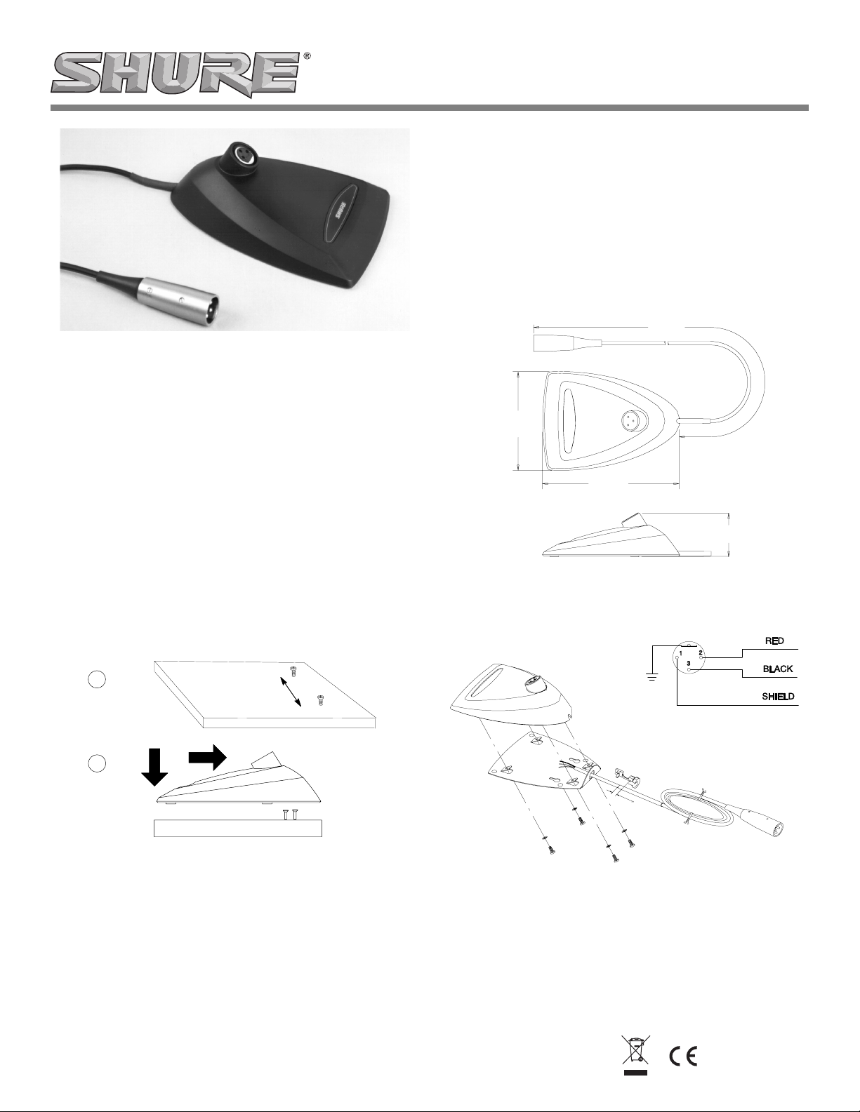
The Shure A412B microphone base allows gooseneck microphones to be quickly mounted in situations where permanent installation is impractical. The angled XLR input connector maintains
a low profile, while inside the base there is ample room for custom
circuitry.
INSTALLATION
Attaching a Microphone to the Base
Insert the XLR connector on the microphone into the female XLR connector on the top of the microphone base.
Securing the Microphone Base to a Surface (Optional)
Model A412B Microphone Base
User Guide
SPECIFICATIONS
Dimensions
See Figure 2
Weight
0.68 kg (1.5 lbs) net
0.91 kg (2.0 lbs) packaged
REPLACEMENT PARTS AND ACCESSORIES
Cable (10 ft)........................................................................C121
Base Plate Bumpers...................................................80A8053A
3.0 m
(10 ft)
11.6 cm
(4 9/16 in.)
16.2 cm
(6 3/8 in.)
5.16 cm
(2 1/32 in.)
1. Install two No. 6 wood screws, two inches apart, on the mounting surface (see Figure 1, diagram A).
2. Place the key holes over the screw heads and push the microphone into position. Adjust the height of the screws as necessary to secure the microphone (see Figure 1, diagram B).
A
2 in.
B
SECURING THE A412B TO A MOUNTING SURFACE
FIGURE 1
DIMENSIONS
FIGURE 2
WIRING DIAGRAM
1 cm
(3/8 in.)
REMOVING THE BACK PLATE
FIGURE 3
©2005 Shure Incorporated
27D2977 (Rev. 4)
Printed in U.S.A.
Page 2

GUIDE DE L'UTILISATEUR DE LA BASE DE MICROPHONE MODÈLE A412B
MODELL A412B MIKROFONSOCKEL BEDIENUNGSANLEITUNG
GÉNÉRALITÉS
La base Shure A412B permet le montage rapide des microphones
à col de cygne dans les situations où une installation permanente
n'est pas pratique. Le connecteur d'entrée XLR en biais permet de
garder un profil bas et l'intérieur de la base est amplement assez
grand pour des circuits spéciaux.
MONTAGE
Montage du microphone sur la base
Brancher le connecteur XLR du microphone sur le connecteur femelle du dessus de la base.
Fixation de la base de microphone sur une surface de montage (option)
1. Poser deux vis à bois no. 6 à 5.1 cm l'une de l'autre, sur la surface de montage (voir la figure 1, schéma A).
2. Placer les trous de montage sur les têtes des vis et pousser le microphone en place. Régler la hauteur des vis selon le besoin pour assujettir le microphone (voir la figure 1, schéma B).
CARACTÉRISTIQUES
Dimensions
Voir la figure 2
Poids
0,68 kg net
0,91 kg emballée
PIÈCES DE RECHANGE ET ACCESSOIRES
Câble de 3 m...................................................................... C121
Amortisseurs de plaque de base................................80A8053A
ALLGEMEINES
Der Mikrofonsockel Shure A412B ermöglicht die rasche Installation von Schwanenhalsmikrofonen in Situationen, in denen sich
die dauerhafte Anbringung als unpraktisch erweist. Der abgewinkelte XLR-Eingangsstecker weist ein flaches Profil auf,
während es innerhalb des Sockels ausreichend Platz für einen
speziell zugeschnittenen Schaltungskomplex gibt.
INSTALLATION
Anbringung des Mikrofons am Sockel
Den XLR-Stecker am Mikrofon in die XLR-Steckbuchse an der Oberseite des Mikrofonsockels einstecken.
(Wahlfreie) Befestigung des Mikrofonsockels auf einer Oberfläche
1. Zwei Holzschrauben Nr. 6 im Abstand von 5.1 cm in die Befestigungsfläche einschrauben (siehe Abbildung 1, Diagramm A).
2. Die Schlüssellöcher über den Schraubenköpfen plazieren und das Mikrofon in die richtige Position drücken. Die Höhe der Schrauben nach Bedarf anpassen, um das Mikrofon sicher zu befestigen (siehe Abbildung 1, Diagramm B).
TECHNISCHE DATEN
Abmessungen
Siehe Abbildung 2
Gewicht
0,68 kg netto
0,91 kg mit Verpackung
ERSATZTEILE UND ZUBEHÖR
Kabel (10 Fuß) ...................................................................C121
Sockelplattenpuffer.....................................................80A8053A
A
2 in.
B
FIXATION DE LA BASE A412B SUR UNE SURFACE DE
MONTAGE • BEFESTIGUNG DES A412B AUF EINER
AUFLAGEFLÄCHE • FIJACION DE LA A412B A UNA
SUPERFICIE DE MONTAJE • FISSAGGIO DELLA BASE A412B
AD UNA SUPERFICIE DI MONTAGGIO
FIGURE 1 ABBILDUNG 1 FIGURA 1
3.0 m
(10 ft)
11.6 cm
(4 9/16 in.)
16.2 cm
(6 3/8 in.)
DIMENSIONS • ABMESSUNGEN
DIMENSIONI
FIGURE 2 ABBILDUNG 2 FIGURA 2
5.16 cm
(2 1/32 in.)
• DIMENSIONES •
2
Page 3

BASE PARA MICROFONO MODELO A412B GUIA DEL USUARIO
GENERAL
La base para micrófono Shure A412B se usa para instalar con
rapidez micrófonos con cuello de ganso en situaciones en las
cuales una instalación permanente resulta poco práctica. El
conector inclinado de entrada tipo XLR mantiene un bajo perfil,
mientras que el interior de la base tiene espacio suficiente para
colocar circuitos especializados.
INSTALACION
Instalación del micrófono en la base
Inserte el conector XLR del micrófono en el conector XLR hembra en la parte superior de la base.
Fijación de la base para micrófono a una superficie (opcional)
1. Atornille dos tornillos para madera N° 6 en la superficie de montaje, separados 5.1 cm (2 pulg) entre sí (vea la Figura 1, diagrama A).
2. Encaje los agujeros alargados sobre las cabezas de los tornillos y empuje el micrófono en su posición de fijación. Ajuste la
altura de los tornillos según sea necesario para fijar el micrófono (vea la Figura 1, diagrama B).
ESPECIFICACIONES
Dimensiones
Vea la Figura 2.
Peso
0,68 kg (1,5 lb) neto
0,91 kg (2,0 lb) en su embalaje
PIEZAS DE REPUESTO Y ACCESORIOS
Cable de 3 m (10 pies).......................................................C121
Pies de caucho para placa de base...........................80A8053A
GUIDA D'USO DELLA BASE PER MICROFONO MODELLO A412B
DESCRIZIONE GENERALE
La base per microfono A412B Shure permette di montare rapidamente microfoni a collo d'oca in condizioni in cui non sia semplice
effettuare un'installazione permanente. Il connettore angolare d'ingresso XLR mantiene un profilo basso, mentre l'interno della base
lascia ampio spazio per circuiti personalizzati.
INSTALLAZIONE
Collegamento del microfono alla base
Inserire il connettore XLR del microfono nel connettore XLR femmina situato nella parte superiore della base.
Fissaggio della base del microfono ad una superficie (facoltativo)
1. Avvitare nella superficie di montaggio due viti per legno N. 6, distanziandole di 5.1 cm (2 pollici) l'una dall'altra (vedi Figura 1, parte A).
2. Posizionare i fori di montaggio sopra le teste delle viti e spingere il microfono in posizione. Regolare adeguatamente
l'altezza delle viti per assicurare il microfono (vedi Figura 1,
parte B).
DATI TECNICI
Dimensioni
Vedi Figura 2
Peso
0,68 kg (1.5 libbre) netto
0,91 kg (2.0 libbre) lordo
COMPONENTI DI RICAMBIO E ACCESSORI
Cavo di 3,0 m (10 piedi) .....................................................C121
Elementi artiurto per la piastra di base.......................80A8053A
RETRAIT DE LA PLAQUE DE BASE • ABNEHMEN DIE
SOCKELPLATTE • RETIRO DE LA PLACA DE BASE •
RIMOZIONE DELLA PIASTRA DI BASE
FIGURE 3 ABBILDUNG 3 FIGURA 3
ROUGE
ROT
ROJO
ROSSO
NOIR
SCHWARZ
NEGRO
NERO
BLINDAGE
ABSCHIRMUNG
BLINDAJE
SCHERMATURA
SCHÉMA DE CÂBLAGE • SCHALTPLAN •
DIAGRAMA DE ALAMBRADO •
SCHEMA CIRCUITALE
3
Page 4

SHURE Incorporated http://www.shure.com
United States, Canada, Latin America, Caribbean:
5800 W. Touhy Avenue, Niles, IL 60714-4608, U.S.A.
Phone: 847-600-2000 U.S. Fax: 847-600-1212 Intl Fax: 847-600-6446
Europe, Middle East, Africa:
Shure Europe GmbH, Phone: 49-7131-72140 Fax: 49-7131-721414
Asia, Pacific:
Shure Asia Limited, Phone: 852-2893-4290 Fax: 852-2893-4055
4
 Loading...