

Page 1
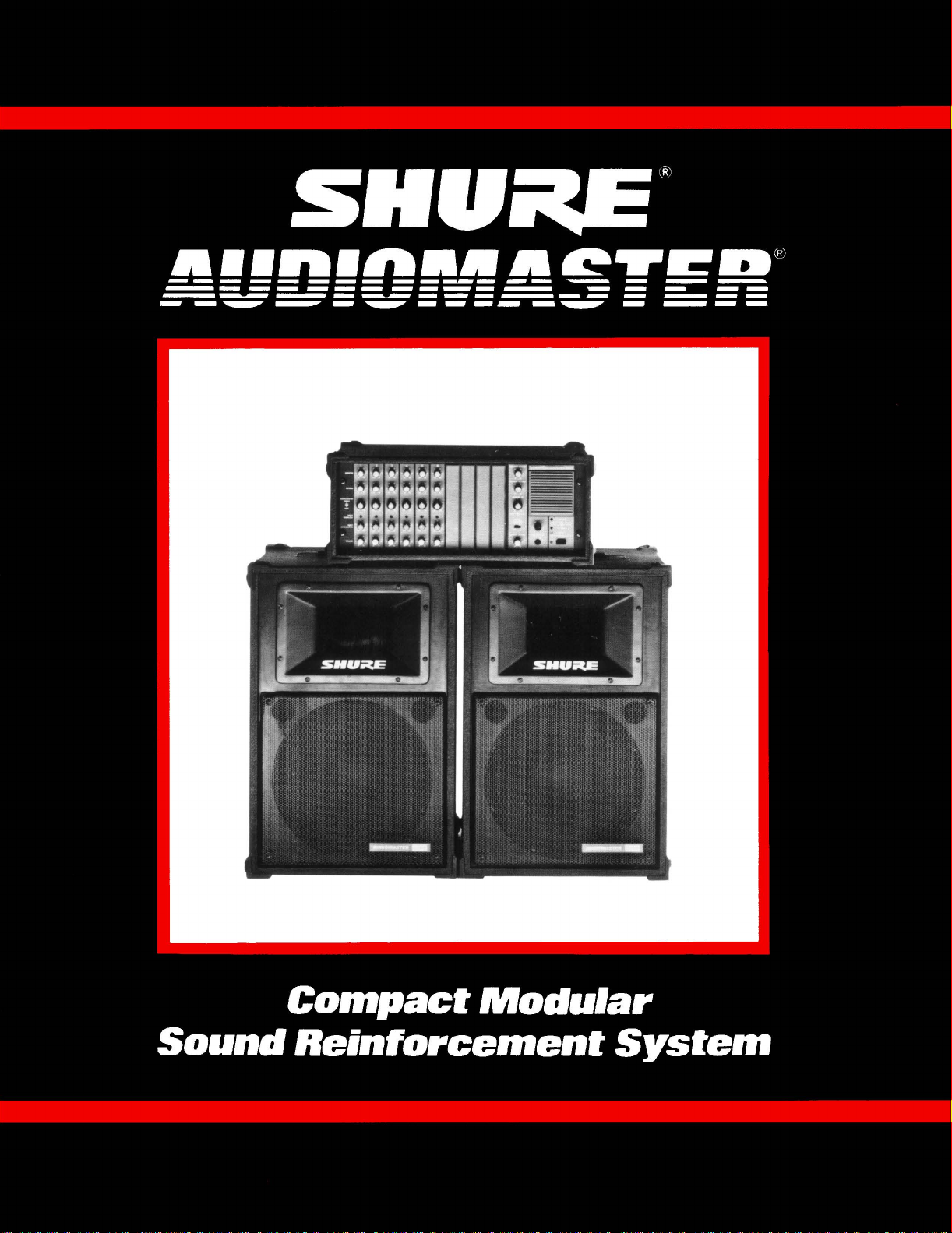
Compact Modular
Sound Reinforcement System
Page 2
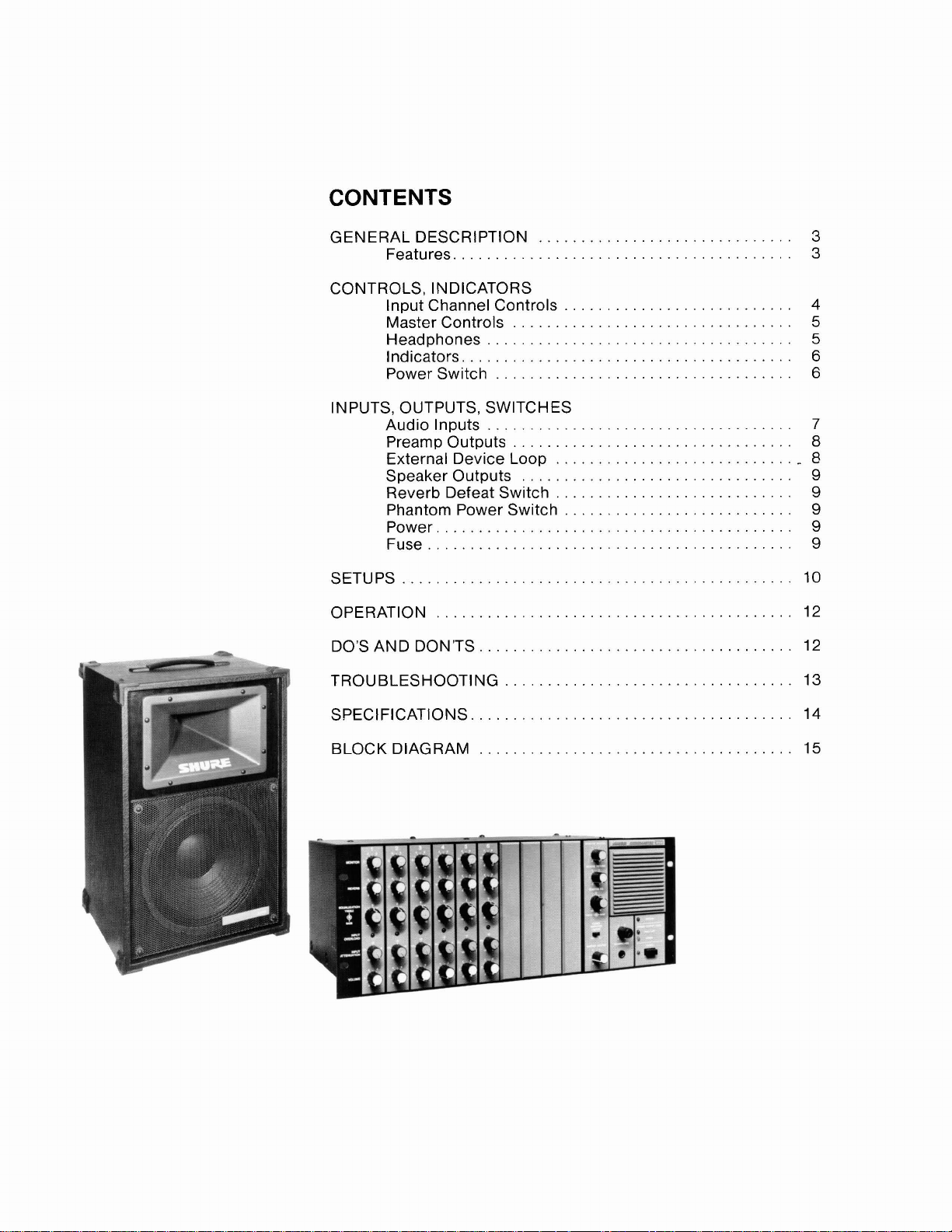
CONTENTS
GENERAL DESCRIPTION
Features
..................................
........................
CONTROLS. INDICATORS
Input Channel Controls
Master Controls
Headphones
Indicators
.......................................
Powerswitch
.................................
....................................
...................................
INPUTS. OUTPUTS. SWITCHES
Audio Inputs
Preamp Outputs
External Device Loop
Speakeroutputs
Reverb Defeat Switch
....................................
.................................
............................
................................
............................
Phantom Power Switch
Power
Fuse
SETUPS
OPERATION
DO'S AND DON'TS
TROUBLESHOOTING
..........................................
...........................................
..............................................
......................................
...................................
............................
...........................
...........................
SPECIFICATIONS
BLOCKDIAGRAM
..........................
.....................................
Page 3

THE SHURE AUDIOMASTERB SYSTEM:
Model 1200 Powermixer
Model 3200 Loudspeaker
Model A1
200MX Expansion Module
Model A1 200C Portable Case
CONGRATULATIONS! You have purchased the
Shure Model 1200 Powermixer, the finest compact
mixer-amplifier available today.
The Model 1200 Powermixer includes a flexible
microphone mixer with six inputs for high- or
impedance sources and a 200-watt power amplifier.
The 1200 is human engineered for ease of setup and
operation. Connection of microphones and other
equipment (tape recorder, equalizer, effects device,
remote amp) is fast and convenient.
The AUDIOMASTER
System,
1200 Powermixer and Model 3200
consisting of the Model
Loudspeaker(s),
works equally well for sound reinforcement or recording of music, vocals, or speech.
The Model 1200 Powermixer is rack-mountable or
portable; a high-power,
&input mixer-amplifier, expandable to 8 or 10 inputs, with famous Shure versatility and ruggedness. Inputs to the Powermixer accept
both high- and low-impedance microphones as well
as amplified instruments or other high-level sources.
Individual
Input Attenuation controls, with overload
indicators, are continuously adjustable to prevent
input overload. The Powermixer has bui It-in reverberation with individual channel and overall level
adjustments. Other effects devices or an equalizer
are easily connected via a post-Master control program loop. An integral power amp Limiter prevents
overload distortion over a wide input signal range.
Pre-Volume Monitor send controls and a pre-Master
Volume Tape Output provide maximum usefulness
in performance or recording applications. The control panel is human-engineered with color-coded
knobs for error-free adjustments while LED readouts
give instant visual notice of overload and operating
status.
The Model 3200 two-way, time-corrected loudspeaker
is a high-power unit designed to be compatible with
the Model 1200 Powermixer. A wide-range frequency
response and excellent sound quality suit it for a
great variety of performance and public-address
situations.
AUDIOMASTER System gives you outstanding
The
sound capability; it's maximally versatile and portable, and it's backed by Shure's traditional quality
and reliability.
low-
Outstanding features of AUDIOMASTER:
1200
POWERMIXER
H
Works equally well for sound reinforcement or
recording of speech, vocals, and music
Designed for churches, schools, clubs, civic and
business organizations, and small performing
H
Operates as a mixer-amplifier for a wide variety of
input sources
Supplied with six input channels (A1 200MX Expansion Modules are available for increase to a total of
eight or ten inputs)
H
HI and LO Z inputs may be used simultaneously
Switchable input attenuators on channels 1 and 2
accommodate high-input-level sources
Phantom power for condenser microphones is avail-
able at any low-impedance input
Built-in spring-type reverb, with independent level
controls for each input
H
Provides external device loop for effects device or
equalizer between PROGRAM MIX OUTPUT and
POWER AMPLIFIER INPUT
H
Pre-Volume MONITOR mix and pre-Master Vol-
ume TAPE Outputs
H
Integral switchable power amplifier Limiter pre-
vents overload distortion
H
High speaker-power output-200 watts into a4-ohm
load
H
An accessory speaker cable (A50SC) is available:
15 m (50 ft) with standard phone plugs, for quick
speaker hookup
Rack mountable or portable with accessoryAl200C
Carrying Case
H
Compact and lightweight: only 178 mm (7 in.) high,
weighs only 12.3 kg (27
Ib)
Listed by Underwriters Laboratories and by Cana-
dian Standards Association as certified
3200
LOUDSPEAKER
Big-system sound quality in a compact enclosure
H
12-inch high-temperature woofer critically tuned
to a sturdy, vented enclosure
H
Constant-directivity type high-frequency horn with
high-frequency compression driver (tweeter)
H
Special TIME SYNCTM time-corrected crossover
network with tweeter protection circuit
H
Metal grille and resilient corner protectors for maximum durability
goups
3
Page 4
FRONT PANEL CONTROLS, INDICATORS..
INDIVIDUAL INPUT CHANNEL CONTROLS
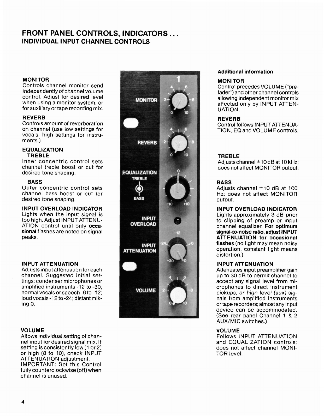
MONITOR
Controls channel monitor send
independently of channel volume
control. Adjust for desired level
when using a monitor system, or
for
auxiliaryortape recording mix.
REVERB
Controls amount of reverberation
on channel (use low settings for
vocals, high settings for instruments.)
EQUALIZATION
TREBLE
Inner concentric control sets
channel treble boost or cut for
desired tone shaping.
.
Additional information
MONITOR
Control precedes VOLUME ("prefader") and other channel controls
allowing independent monitor mix
affected only by INPUT ATTENUATION.
REVERB
Control follows INPUT ATTENUATION, EQ and VOLUME controls.
TREBLE
Adjusts channel k1O dB at
does not affect MONITOR output.
10
kHz;
BASS
Outer concentric control sets
channel bass boost or cut for
desired tone shaping.
INPUT OVERLOAD INDICATOR
Lights when the input signal is
too high. Adjust
ATlON control until only
flashes are noted on signal
sional
peaks.
INPUT ATTENUATION
Adjusts input attenuation for each
channel. Suggested initial settings: condenser microphones or
amplified instruments -1
normal vocals or speech
loud vocals
ing
0.
VOLUME
Allows individual setting of channel input for desired signal mix. If
setting is consistently low (1 or 2)
or high
ATTENUATION adjustment.
IMPORTANT: Set this Control
fully counterclockwise (off) when
channel is unused.
(8
INPUTATTENU-
-1
2 to
-24;
distant mik-
to
lo),
check INPUT
occa-
2
to -30;
-6
to
-1
2;
BASS
Adjusts channel -+I0 dB at 100
Hz;
does not affect MONITOR
output.
INPUT OVERLOAD INDICATOR
Lights approximately 3 dB prior
to clipping of preamp or input
channel equalizer.
signal-to-noise ratio, adjust INPUT
ATTENUATION for occasional
flashes
operation; constant light means
distortion.)
INPUT ATTENUATION
Attenuates input preamplifier gain
up to 30 dB to permit channel to
accept any signal level from microphones to direct instrument
pickups, or high level (aux) signals from amplified instruments
or tape recorders; almost any input
device can be accommodated.
(See rear panel Channel
AUX/MIC switches.)
VOLUME
Follows INPUT ATTENUATION
and EQUALIZATION controls;
does not affect channel MONITOR level.
(no light may mean noisy
For optimum
1
&
2
Page 5
MASTER CONTROLS
Additional information
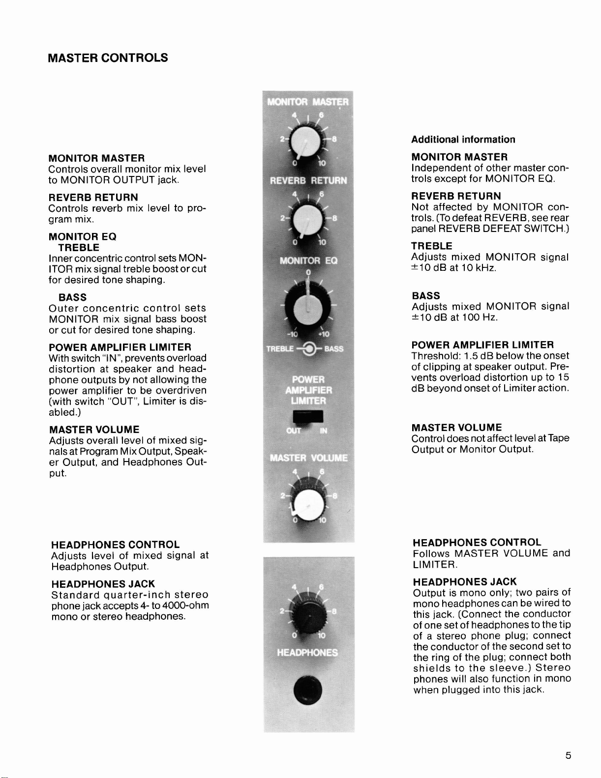
MONITOR MASTER
Controls overall monitor mix level
to MONITOR OUTPUT jack.
REVERB RETURN
Controls reverb mix level to program mix.
MONITOR EQ
TREBLE
Inner concentric control sets MONITOR mix signal treble boost or cut
for desired tone shaping.
BASS
Outer concentric control sets
MONITOR mix signal bass boost
or cut for desired tone shaping.
POWER AMPLIFIER LIMITER
With switch "IN", prevents overload
distortion at speaker and headphone outputs by not allowing the
power amplifier to be overdriven
(with switch "OUT", Limiter is disabled.)
MASTER VOLUME
Adjusts overall level of mixed signals at Program Mix Output, Speaker Output, and Headphones Out-
put.
MONITOR MASTER
Independent of other master con-
trols except for MONITOR
EQ.
REVERB RETURN
Not affected by MONITOR controls. (To defeat REVERB, see rear
panel REVERB DEFEAT SWITCH.)
TREBLE
Adjusts mixed MONITOR signal
*I0 dB at 10 kHz.
BASS
Adjusts mixed MONITOR signal
210 dB at 100 Hz.
POWER AMPLIFIER LIMITER
Threshold: 1.5 dB below the onset
of clipping at speaker output. Prevents overload distortion up to 15
dB beyond onset of Limiter action.
MASTER VOLUME
Control does not affect level at Tape
Output or Monitor Output.
HEADPHONES CONTROL
Adjusts level of mixed signal at
Headphones Output.
HEADPHONES JACK
Standard quarter-inch stereo
phone jack accepts
mono or stereo headphones.
4-
to 4000-ohm
HEADPHONES CONTROL
Follows MASTER VOLUME and
LIMITER.
HEADPHONES JACK
Output is mono only; two pairs of
mono headphones can be wired to
this jack. (Connect the conductor
of one set of headphones to the tip
of a stereo phone plug; connect
the conductor of the second set to
the ring of the plug; connect both
shields to the sleeve.) Stereo
phones will also function in mono
when plugged into this jack.
Page 6

INDICATORS
OVERLOAD
Red LED flashes to warn of unsafe
operating conditions; lights continuously if power amp shuts down
because of overheating or because
of an abnormal speaker load
short circuit).
(i.e., a
Additional information
OVERLOAD
LED
If OVERLOAD
flashes or stays on, disconnect or
correct any abnormal load or obstructed airflow. All low level circuitry remains operative
output will not be affected during
power amp shutdown.) Power amp
and LED operation return to normal
when unsafe condition is removed.
continually
(e.g., TAPE
POWER OUTPUT LEVEL
PEAKILIMIT (RED) LED
Limiter Out: Lights just before
power amp clips to warn of over-
load distortion.
Limiter In: Lights at approximate
onset of Limiter action.
POWER OUTPUT LEVEL
NORMAL (YELLOW) LED
Lights to indicate a typical minimum level signal present at amplifier output.
POWER POWER
GREEN LED GREEN LED
Lights when Power switch is On.
POWER SWITCH
Pushbutton switch turns power on
and off.
NOTE:
In case of sustained overheating,
internal thermal overload switch
automatically turns power off to
entire unit. Unit should return to
normal operation after sufficient
cooldown time. (Allow at least
hour.)
POWER OUTPUT LEVEL
PEAKILIMIT (RED) LED
Limiter Out: Lights
onset of amplifier clipping.
Limiter In: Lights 0.5 dB before
onset of Limiter action, indicating
that the Limiter is functioning
normally.
POWER OUTPUT LEVEL
NORMAL (YELLOW) LED
Lights when signal level at speaker jacks is above
watt).
Remains illuminated when power
amplifier temporarily shuts down
due to overload.
1
2
dB below the
1.4
V RMS (0.5
Page 7

REAR PANEL INPUTS, OUTPUTS, SWITCHES..
AUDIO INPUTS
Additional information
.
1
&
CHANNEL
AUXIMIC switch in
allows
recorder,f~ tun1
to be connected
MIC
microphones or
hig h-impedance
hiah level aux source (tape
position for
2
er, CD player, etc.)
to HI
high-impedance
other low-level
sources. phones simultaneously with AUX
AUX
Z
input. Use
position
CHANNEL
Switch in
fixed
allowing virtually any high level
source to be connected to HI
MIC inputs on these 2 channels.
Use of low-impedance micro-
inputs
1 & 2
AUX
position provides
22
dB added attenuation
IS
not recommended.
Z
--
HI
Z
Quarter-inch phone jack for connection of high-impedance micro-
phones, direct instrument pickups,
keyboards, amplified instruments,
tape recorders or other high-level
sources.
BAL LO Z
3-socket professional audio input
connector for low-impedance dyna-
mic, ribbon, or condenser micro-
phones.
source is connected to channel's
HI
in AUX position.)
(Do not use if high-level
Z
input and MICIAUX switch is
Additional information
HI
Z
Can be used with line matching
transformer
mit two low-impedance microphones on same channel (the second into the
recommended for condenser microphones unless they are battery
powered.
BAL LO
Accepts both balanced and unbalanced low-impedance sources.
Built-in switchable
power supply permits powering
most condenser microphones; see
rear-panel 24 VDC switch.
(A95UF, A85F) to per-
LO
Z
connector.) Not
Z
+24V phantom
CHANNEL
HI
Z
and
at the same time with similar micro-
phones (one high and one low
impedance.)
NOTE:
If it is desired to use a magnetic
phono cartridge and turntable
with the 1200, the use of a Shure
M64A Phono Preamp is recommended, operating into the AUX (HI
inputs.
CHANNEL
Blanks in rear panel accept Model
A1
200MX Input Expansion Modules, each containing two channels.
You can add these four channels,
identical to channels
for additional mixing capability.
Front panel channel nomenclature
is under removable front panel
channel covers. (Expansion modules should be installed by qualified service personnel only.)
1-6
LO
Z
inputs can be used
7-10
3
through
Z)
6,
Page 8

OUTPUTS AND INPUTS
(quarter-inch phone jacks)
Additional information
MONITOR OUTPUT
Unbalanced high-level output unaffected by Input Channel controls
except INPUT ATTENUATION and
individual MONITOR. For separate
monitor amplifier system, or remote
amplifierlspeaker.
TAPE OUTPUT
Designed for connection to "TAPE
IN" on tape recorder or to aux input
of similar device.
EXTERNAL DEVICE LOOP
MONITOR OUTPUT
Z,
unbalanced, aux level, pre-
HI
fader output, affected by MONITOR EQ and MONITOR MASTER
controls.
TAPE OUTPUT
Unbalanced high-level HI
put is post-channel Volume controls, and pre-master controls; may
be used without speakers con-
nected to the 1200's amplifier.
Z
out-
PROGRAM MIX OUTPUT AND POWER AMPLIFIER INPUT
These two
delay, compressor, or noise gate to be connected between the PROGRAM MIX OUTPUT
and the POWER AMP INPUT. The PROGRAM MIX OUTPUT can also be used as a
post-MASTER VOLUME control send to an external amplifier, recorder, etc., without
interrupting the signal to the internal amplifier. The POWER AMPLIFIER INPUT allows
the 1200's internal amplifier to be used independently of its mixer section. Using the
POWER AMPLIFIER INPUT jack interrupts the program send to the power amp.
fader PROGRAM MIX OUTPUT is affected by all program input and output controls
except LIMITER; POWER AMPLIFIER INPUT is pre-LIMITER.
NOTE: The External Device Loop can be used to connect two 1200's together for an
expanded capability of 400 watts total speaker output power. Connect the PROGRAM
MIX OUTPUT of the first 1200 to the PROGRAM MIX OUTPUT of the second 1200. All of
the inputs to both 1200's will then appear at the speaker outputs of each. Set the channel
controls
its speaker outputs. When this procedure is followed, the MASTER VOLUME controls
will require higher settings to obtain the same level at the speakers because each
PROGRAM MIX OUTPUT loads the other. With appropriate MASTER VOLUME control
settings, the full 400 watt total speaker output power is available from the two Model
1200 power amplifiers.
%-inch phone jacks allow an external equalizer or effects device such as echo,
Post-
normdlly. Each MASTER VOLUME control determines the level of all inputs at
Page 9

SPEAKER OUTPUTS
Two parallel-wired jacks for min-
imum 4-ohm load, maximum
watt output. Suggested speaker
load: two Model 3200 Loudspeakers (8 ohms each, two in parallel
equal 4 ohms), or one or two other
high-power
4-ohm speaker. Use
sory Speaker Cable* to connect
speakers. If
(or any other 8-ohm speaker) is
used, maximum power output will
be
120'watts.
*I 5 m (50 ft) with standard X in. phone plug at each end.
&ohm speakers, or one
A50SC Acces-
only one 3200 soeaker
200-
Additional information
SPEAKER OUTPUTS
Connecting too many speakers to
either or both jacks may result in
combined load below 4-ohm minimum; operation may then cause
OVERLOAD LED to light and power
amp to shut down. Note that no
damage will result; Model 1200 is
protected against abnormal speaker
loads and short circuits. Again, if
two 1200's are connected together
via the Program Mix jacks, be sure
that maximum load on each power
amplifier does not fall below 4
ohms.
SWITCHES
REVERB DEFEAT SWITCH
Quarter-inch phone jack for connection of remote switch to disable reverb.
PHANTOM POWER SW17
Turn On when powering
pedance condenser microphones;
turn Off when not reauired.
'C H
low-
AC
POWER
Additional information
REVERB DEFEAT SWITCH
Without changing preset reverb
controls.
minus reverb. Dc switching allows
use of unshielded cable. When
switch is closed (circuit shorted),
reverb signal is removed from program mix by connecting tip to shell
(ground) of plug. A foot switch
works well.
PHANTOM POWER SWITCH
Supplies 24 Vdc to all low-impedance microphone inputs. Balanced low-impedance and unbalanced
ribbon microphones can be used
in combination with condenser
microphones.
anced low-impedance microphones with
oermits temoorarv outout
high-im-pedance dynamic or
Do NOT use unbal-
24
VDC switch On.
UNSWITCHED AC GROUNDED OUTLET
Provides up to 100 watts of ac power to accessory equipment (tape recorder,
graphic equalizer, effects device, phono preamp, etc.) Outlet is not switched, use switch on accessory; outlet is not intended for use with
power equipment such as power amplifiers.
AC LINE CORD
Connect to ac power (1 20 Vac *1 Ox, 50160 Hz). Use only 16 AWG or larger
3-wire extension cords. Model 1200 may draw up to 5 amps from ac supply.
5A, 250V FUSE
Protects Model 1200 power supply against overload. Replace only with
identical size and type fuse. To remove, press and rotate fuseholder counterclockwise using finger or screwdriver in slot.
high-
Page 10

SETUPS
The AUDIOMASTER system is extremely versatile; consequently it can be used in a wide variety of applications.
The setups shown in this section briefly illustrate the different combinations that are possible.
NOTE: Use proper cables when interconnecting equip-
ment. Low-level audio connections require shielded (coax-
ial type) cable. Speaker leads need not be shielded, but
UmmmmlEn
1200
POWllMllEI
(AWG).
,,
-ww
m.,.
"""7-
ws.
m.&e
y.
zF"
should be at least 18-gauge
BASIC SOUND REINFORCEMENT
Connect as many microphones as required, and set the
operating controls as desired. Attach one Model 3200
Loudspeaker to each speaker output.
2*YiP'
YODEL
SOUND REINFORCEMENT WlTH A GRAPHIC EQUAL-
[OR EFFECTS DEVICE)
IZER
connect a graphic equalizer or effects device to the EXTERNAL DEVICE LOOP: PROGRAM MIX OUTPUT to graphic
equalizer input, graphic equalizer output to POWER AMPLIFIER INPUT. Connect the speakers as for Basic Sound
Reinforcement.
,
SBAPHIC
EOUALtZER
,
-
(SECOND
SPEAKER
OPTIONAL)
SOUND REINFORCEMENT AND TAPE RECORDING
Attach 1 Model 3200 Loudspeaker to each speaker out-
put; connect the TAPE OUTPUT to the tape recorder Aux
Input.
NOTE: The TAPE OUTPUT level is independent of the
MASTER VOLUME control. Use the tape deck input level
controls to set the record level.
YODEL
,100
.OWEIYI'I"
SOUND REINFORCEMENT WlTH A SEPARATE MAlN
AMP AND SPEAKERS, USING THE INTERNAL AMP FOR
MONITOR SPEAKERS
Connect a shielded cable from the MONITOR OUTPUT to
the POWER AMPLIFIER INPUT. Connect monitor speakers (with minimum 4-ohm total load) to the SPEAKER
OUTPUTS. Connect a shielded cable from the PROGRAM
MIX OUTPUT to an external amplifier (or crossover/
amplifiers); and connect main
amplifier(s). The 1200 MONITOR MASTER controls the
output level from the 1200 amplifier to the monitor speakers; the 1200 MASTER VOLUME controls the PROGRAM
MIX OUTPUT level to the external main amplifier and
speakers.
speaker(s) to the external
AMPLIFIER
PI
MAlN SPEAKERS
[
I
A1
MONITOR SPEAKERS
Page 11

SOUND REINFORCEMENT WITH A SEPARATE MONI-
TOR AMP AND SPEAKERS
Connect two speakers to the two Powermixer SPEAKER
SOUND REINFORCEMENT AND RECORDING WITH A
GRAPHIC EQUALIZER, TWO
MAIN SPEAKERS, AND A
REMOTE (OR STAGE MONITOR) AMP AND SPEAKERS
OUTPUTS. Connect the MONITOR OUTPUT to the moni- Connect the main speakers to the 1200 SPEAKER OUT-
tor amplifier aux input; connect the monitor speakers to
the monitor amp. (Only INPUT ATTENUATION, channel
EQ
MONITOR, MONITOR
and MONITOR MASTER con-
trols affect the MONITOR OUTPUT signal.)
MON~TO~
SPEAK^^^
PUTS. Connect the remote amp to the MONITOR OUTPUT; connect the remote speakers to the remote amp.
Connect the tape recorder to the TAPE OUTPUT; connect
the PROGRAM MIX OUTPUT to the graphic equalizer
input; connect the equalizer output to the POWER AMPLIFIER INPUT. All Powermixer program controls affect the
Main Speakers; only INPUT ATTENUATION and MONITOR controls affect the remote amp.
SOUND REINFORCEMENT WlTH A STAGE MONITOR
SPEAKER
Connect one 3200 Loudspeaker to one of the Powermixer
Speaker Outputs. Connect the Stage Monitor Speaker to
the other Powermixer Speaker Output. All Powermixer
CONNECTING TWO 1200's TOGETHER FOR TOTAL
AMPLIFIER OUTPUT OF 400 WATTS TO FOUR 8-OHM
SPEAKERS
Connect the PROGRAM MIX OUTPUT of the first 1200 to
the PROGRAM MIX OUTPUT of the second 1200. Connect two
&ohm speakers to the first 1200; connect two
8-ohm speakers to the second 1200. All inputs to both
1200's appear at all speaker outputs. The Master controls
of each 1200 affect only the speakers connected to it.
Because each PROGRAM MIX OUTPUT loads the other,
set the MASTER VOLUME control on each 1200 to a
Page 12
OPERATION
1. Position the microphones and connect them to the
AUDIOMASTER Powermixer 1200. If more than six
microphones are required, add up to two A1
Expansion Modules. Each Module adds two lowimpedance and two high-impedance microphone
inputs. (Modules are for installation by qualified service personnel only.) If necessary, it is possible to use
both inputs on each channel. (See Audio Inputs,
page
7.)
If long microphone cable runs (more than
6.1 m
impedance microphones and cables to minimize
high-frequency loss and interference.
2. Position the speakers and connect them to the
ermixer. Make sure the combined rated speaker load
is not lower than 4 ohms.
*NOTE: The 1200 is designed to deliver 200 watts
(sine wave undistorted max) into a 4-ohm load. However, to avoid excessive heating of components,
sustained operation under these conditions is not
recommended. Continuous operation with normal
program material at maximum undistorted output is
permissible.
3.
Connect any external devices (see Setups section)
such as a tape deck, graphic equalizer, effectsdevice,
monitor or remote amp and speakers.
4.
Connect the Model 1200 power cord to an ac source
capable of supplying 600 watts. If extension cords
are used, make sure they are 16 AWG or larger.
5. Make sure the front and back panel ventilation grilles
are not blocked.
6. Set the front panel controls as desired using the
following guidelines for initial settings: set the INPUT
ATTENUATION control clockwise; for optimum
signal-to-noise ratio, set individual channel controls
high and masters low. Set unused channel VOLUME
and MONITOR controls counterclockwise.
7.
Use program material similar to actual performance,
listen to the system and make final adjustments for
the most pleasing sound.
8.
During operation, observe the various LED indica-
tors for possible control adjustments:
A. INPUT OVERLOAD-If red LED is on constantly,
B.
C. POWER OUTPUT LEVELIPEAK-When Limiter
D.
[20 ft.1) are needed, use balanced low-
use the INPUT ATTENUATION to reduce the input
signal and eliminate overload distortion. (Adjust
control for occasional flashing on program peaks.)
OVERLOAD-Red LED lights to indicate power
amp has shut off due to abnormal speaker load
(such as a short circuit) or overheating due to
restricted air flow. Correct abnormal speaker
load condition or remove any obstruction to front
and back panel air vents. Power amplifier will
automatically return to normal operation (and LED
will turn off) after elimination of shutdown cause.
is
out,
red LED flashes just before power amp
clipping. (If LED flashes continually, reduce MASTER VOLUME control setting, or switch Limiter
in.)
POWER OUTPUT LEVELILIMIT-When Limiter
is in, red LED flashes to indicate onset of Limiting.
NOTE: During heavy limiting, this LED may remain
on without flashing.
200MX
Pow-
E. POWER OUTPUT LEVELINORMAL-Yellow LED
lights to indicate output power at speaker jacks is
in a typical operating range (typical minimum out-
put signal of 0.5 watt with 4-ohm load). In situations requiring low output power, this LED may
flash only occasionally or not at all.
NOTE: No damage will be done to the 1200 if it is
operated without a speaker load connected. The
yellow LED will still function in this condition,
indicating a signal is present at the speaker
outputs.
F. POWER-Green LED lights when power switch
is on; remains illuminated even when power amp
shuts down due to overload.
NOTE: For portable use, the
ble Case is recommended. If the 1200 is to be mounted
in an enclosed equipment rack, adequate ventilation
should be provided for proper operation. If possible,
the rear of the rack cabinet should be open or have
adequate ventilation area.
Le 1200 est
sinusoi'dale
charge de
elements ne chauffent, un fonctionnement prolonge
dans ces conditions est deconseille. Avec des programmes normaux, I'appareil peut fonctionner en
continu sur un niveau de sortie maximum sans
distorsion.
coney
a
maximum sans distorsion) sur une
4
ohms. Cependant, pour eviter que les
A1 200C Accessory Porta-
pour delivrer 200 watts (onde
FOR YEARS OF DEPENDABLE
SERVICE
The AUDIOMASTER System is exceptionally well
designed, with all components of the highest quality,
operating well within their respective ratings to assure
long life. The following list of Do's and Don'ts describes
minimal operating precautions and maintenance to provide years of dependable service.
DO use a 16 AWG or larger heavy-duty 3-conductor
extension cord when additional line cord length is
needed.
DON'T replace the rear-panel fuse with
or type. Use only 5 A, 250 V, Type 3AG.
DON'T operate the Powermixer with its air vents blocked,
or placed on a radiator or heat-producing equipment.
Avoid operation in direct, hot sunlight.
DO unplug the Powermixer before cleaning. Use only
mild detergent and a damp (never wet) cloth to clean
the outer surfaces; DON'T use strong solvents or clean-
ing fluids.
DON'T use unbalanced low-impedance microphones
with the PHANTOM
not required for powering condenser microphones. If
phantom power is in use, connect unbalanced
impedance microphones through a line matching transformer (Shure
will not affect balanced low-impedance dynamic
microphones.
DON'T risk fire or shock hazard by operating the Model
1200 in the rain.
24Vswitch on; turn off the switch if
A95UF) to a HI Z input. Phantom power
a
different size
low-
Page 13

TROUBLESHOOTING
Should any difficulty be encountered in operation of your AUDIOMASTER System, the
trouble can often be traced to some simple source. The following is offered as a basic
guide to solving this kind of problem.
SYMPTOM PROBABLE CAUSE AND CORRECTION
Powermixer is "dead" (no
output, POWER LED off)
Power amplifier stage not
operating (OVERLOAD
LED is on)
No signal at speaker (all other
functions appear normal) cables.
Fuse blown
1. Check that ac power source is "live" and Model 1200
2. Check that POWER switch is on.
3. Check that rear panel fuse (5 A,
4. If the 1200 has turned off due to excessive internal
1. Check air vents for blockage.
2. Check total speaker load (must be no lower than
3.
4. Turn MASTER VOLUME control down for several min-
1.
2. Check settings of channel VOLUME and MASTER
3. Check connections to EXTERNAL DEVICE LOOP.
1. Replace with identical fuse (5 A,
2. If second fuse blows, have Model 1200 checked
is plugged in.
250V) is good.
temperatures, allow at least an hour for cooling, and
reactivate unit. If difficulty persists have Model 1200
checked by qualified service personnel.
4 ohms) and for possible shorted speaker cable.
Check that internal fan is operating (fan is located
on rear panel).
utes to allow proper cooling. If difficulty persists, have
Model 1200 checked by qualified service personnel.
Check for defective or improperly connected speaker
VOLUME controls.
250V, 3AG).
by qualified service personnel.
One of two inputs on same
channel not working
properly (both
3-pin jacks in use)
NPUT OVERLOAD LED
flashing
NOTE: Occasional
flashing is ok.
Loud clicks when certain
microphones or cables
are used
No MONITOR output (program
output normal)
Sound quality poor (weak
or thin)
%-inch and
1.
Make sure similar microphones are used on both
inputs, and microphone impedances match the
puts used.
2. Make sure a low-impedance microphone is not used
with aux level equipment on other input.
3. Make sure microphone switches are on; check
microphone cables.
1. Adjust INPUT ATTENUATION counterclockwise to
reduce channel input level.
2. Reduce input signal level at source.
1.
Make sure PHANTOM 24V switch is not on (when
not needed).
2. Make sure unbalanced low-impedance microphone
or cable is not used when PHANTOM switch is on.
3.
Check for defective microphone cables.
1.
Make sure channel MONITOR and MONITOR
MASTER controls are turned up.
2. Make sure external Monitor amp volume control is
turned up.
3. Check for defective cable to MONITOR output jack.
1. Check for excessive treble boost or bass cut on
equalization controls.
2. Check for defective cables.,
3.
Check impedance match at input.
im-
Page 14

SPECIFICATIONS
TY pe
Mono Powermixer
Frequency Response
Flat + 1, -3 dB, 40 Hz to 20 kHz (any input to any output)
Inputs
Six input channels: six unbalanced high- and/or balanced low-impedance inputs; channels
impedance inputs switchable to Aux level; available
expansion modules* each contain 2 high- and 2
impedance microphone inputs; two modules (4 channels) can be added to each 1200
Power Output
200 watts minimum with 4 ohm speaker
120 watts minimum with 8 ohm speaker
Distortion
THD
and 20 kHz (180 watts to 4 ohms, measured from
impedance input, lnput Attenuation, individual channel
and Master Volume controls at typical user settings)
IM
ohms, Input Attenuation, individual channel and Master
Volume controls at typical user settings)
Low- and High-Frequency Equalization
and Monitor)
"10dB at 100 Hzand 10 kHz
lnput OVERLOAD Indicators
Illuminate 3 dB before clipping of input preamplifier or
equalizer stage
Power Amp Limiter
Threshold: 1.5 dB below speaker output clipping level
lnput signal range: 15 dB beyond limiting threshold
Output PEAKILIMIT lndicator
With Limiter Out: Lights 2 dB before clipping at speaker
outputs
With Limiter In: Lights 0.5 dB before onset of Limiter
action
Output NORMAL lndicator
Lights when speaker output level is greater than 1.4
Vrms (0.5 W into 4 ohms)
lnput Sensitivity
BAL LO Z: -66
HI
AUX: -26 dBV (50 mV)
PA INPUT: 0 dBV (1.0 V)
lnput Clipping Level
l
N PUT CLIPPING
BAL LO Z -33 to -3 dBV 0 to -30
HI Z -1 1 to +18 dBV 0 to -30
AUX
PA INPUT -1
Voltage Gain
l N PUT OUTPUT
LO
HI Z
AUX 55 dB 25dB 31 dB 42 dB
PA
(1 kHz, 120 Vac, 1 % THD)
typically less than 0.15% at 1 kHz, 0.35% at 70 Hz
distortion typically less than 0.4% (1 16 watts to 4
(full power output)
Z:
-44 dBV (6.3 mV)
(at 1 kHz)
Z
dBV (0.5 mV)
LEVEL
dBV
-
mV)
49dB 60dB 29dB
-
(22 to 707
mV to 8.41 V)
(281
+6 to +36 dBV 0 to -30
2 to 63 V
(891 mV)
SPEAKER PGM MIX MONITOR PHONES TAPE
95dB
73 dB 43dB
29 dB
65dB 71 dB 82dB 51 dB
l
(Individual channel
ATTENUATION
16dB
and 2 high-
low-
low-
--
11 dB
-
Output Clipping Level
OUTPUT MINIMUM CLIPPING LEVEL
SPEAKER +29
MONITOR
PROGRAM MIX +18dBV (7.9V)
PHONES
TAPE +18
Impedance
l N PUTS ACTUAL FOR USE WITH
LO Z MIC
HI Z MIC 130 kQ 100 kQ or less
AUX 50
PA 50
OUTPUTS
MONITOR
PROGRAM MIX
TAPE
PHONES
SPEAKER
Hum and Noise
Less than -126 dBV equivalent input hum and noise
(20 Hz to 20 kHz, LO
Noise
Less than -1 27 dBV equivalent input noise (300 Hz to
20 kHz, LO Z input to SPEAKER output)
Signal-to-Noise Ratio
Greater than 80 dB (below full output) at typical control
settings
Phantom Power
24 Vdc k 10% open circuit, 1.8 k series resistance
Power Requirements
120 Vac k lo%, 50160 Hz, 420 watts typical with no ac
receptacle load
AC Convenience Receptacle
120 Vac, 100 watts maximum
Certifications
Listed by Underwriters Laboratories Inc. and by
Canadian Standards Association as certified
Environmental Conditions
Operating Temperature: -7 to 43OC (20 to 1 10°F)
Storage Temperature: -40 to 74OC (-40 to 165OF)
Relative Humidity (Operating and Storage): 0 to 95%
Overall Dimensions
191 mm Hx483mmWx343mm D(7-Wx19x13-Win.)
Weight
12.3 kg (27 Ib)
18.2 kg (40 Ib) in A1 200C Carrying Case
RECOMMENDED LOUDSPEAKERS
AUDIOMASTER Model 3200, 100 W, 8 Q, vented two-way
speakers
OPTIONAL ACCESSORIES
Carrying Case A1 200C
lnput Expansion Module*
(2 channels, 2 each HI Z and LO Z inputs).
Speaker Cable, 15 m (50 ft) with phone plugs
Line Matching Transformer (LO Z to HI Z)
240-V Conversion Kit* RKC209
Phono Preamp M64A
"For installation by qualified service personnel only.
................................
........................
.................................
1
2.4
2.4
2.4
430
-
Z
input to SPEAKER output)
dBV (28 V)
f18dBV (7.9V)
+
16 dBV (6.3 V)
dBV (7.9 V)
kQ 75 to600 Q
kQ 10 kQ or less
kQ 10 kQ or less
kQ 2 kQ or more
kQ 2 kQ or more
kQ 2 kQ or more
Q 4 Q or more
4 Q or more
.
A1200MX
......
.........
A5OSC
A95UF
Page 15

Page 16

Copyr~ght
27A8131(GG)
1987.
Shure
Brothers
Inc
Printed
in
JAPAN
 Loading...