

Page 1
General
Ñ
Ñ
RK363 (UA) and RK365 (MA)
Upgrade Kit for
U4S/U4D UHF Receivers
This Upgrade Kit is for Shure Model U4S and U4D Receivers, Versions
1.5x and earlier. It allows them to become fully integrated with the Shure
UA888 Networking System. Each kit includes a display circuit board with a
pre-programmed EEPROM, rubber actuators, and plastic knobs.
Note:
These procedures should only be attempted by a qualified technician.
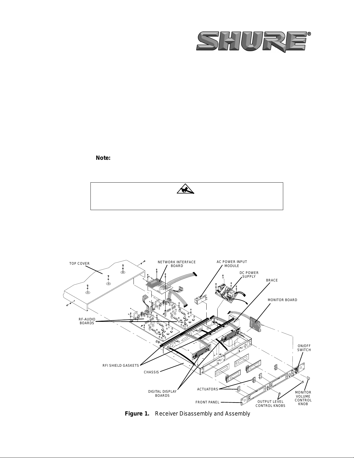
Receiver Disassembly and Assembly
ATTENTION
Observe precautions when handling this static-sensitive device.
Top Cover Removal
1. Disconnect the U4 Receiver from the AC power supply.
2. Remove five screws and washers from the top of the receiver and two screws
and washers from the sides of the receiver. See Figure 1.
3. Slide the top cover off of the receiver to expose the circuit boards.
TOP COVER
RF-AUDIO
BOARDS
NETWORK INTERFACE
BOARD
AC POWER INPUT
MODULE
DC POWER
SUPPLY
BRACE
MONITOR BOARD
ON/OFF
SWITCH
RFI SHIELD GASKETS
CHASSIS
DIGITAL DISPLAY
BOARDS
ACTUATORS
FRONT PANEL
OUTPUT LEVEL
CONTROL KNOBS
MONITOR
VOLUME
CONTROL
KNOB
Figure 1. Receiver Disassembly and Assembly
E2002 Shure Incorporated Printed in U.S.A.
27B8634 (BD)
Page 2

RK363/RK365 Network Upgrade Kit for U4S and U4D Diversity Receivers
Display Board Removal
1. Remove and discard the Output Level Control knob.
2. Disconnect the ribbon cable(s) linking the digital display board(s) to the rf/Audio
board(s) P202. Disconnect other cables as necessary.
3. Remove the steel brace inside the receiver by removing the three screws and
washers securing it to the bottom of the chassis.
4. Remove each display board by removing the two screws and washers securing
the board to the back of the front chassis. Then pull the board away from the
chassis and lift the board out.
Front Panel Removal
1. Remove and discard the five hexnuts and star washers securing the front panel
to the chassis. Use a flexible spring socket driver.
2. Label and disconnect the power on/off switch from the power supply wires.
3. Remove the plastic Output Level Control knob(s) by pulling it away from the front
panel.
4. Remove the Monitor Level Control knob by pulling it away from the front panel.
5. Carefully pull the front panel away from the chassis.
6. Remove and discard the rubber actuators.
U4 Receiver Reassembly
Attaching the Front Panel
1. Retrieve the new rubber actuators from the Upgrade Kit and insert them into the
receiver.
2. Retrieve the hexnuts with the nylon inserts from the Upgrade Kit and use them
to secure the front panel to the chassis. Use a flexible spring socket driver.
3. Reconnect the power on/off switch to the tagged wires.
Display Board Installation
1. Remove the pre-programmed display board from the Upgrade Kit.
2. Secure the display board to the chassis with the previously removed screws and
washers.
3. Reinstall the steel brace and secure it with the previously removed screws and
washers.
4. Route the ribbon cable and connect it to rf–Audio Board P202.
5. Make sure the rf shielding gaskets are in place.
6. Reinstall the top cover, and secure it with the previously removed screws and
washers.
7. Retrieve the Output Level Control knobs from the Upgrade Kit and install them
8. Install the previously removed Monitor Level Control knob.
Testing the Upgraded Receiver
1. Turn the receiver on.
2. Press and hold the “+” and “–” keys on the receiver front panel simultaneously.
If the upgrade kit has been successfully installed, “Version 2.x” will appear on
the front panel display in approximately 3 seconds.
SHURE Incorporated Web Address: http://www.shure.com
222 Hartrey Avenue, Evanston, IL 60202–3696, U.S.A.
Phone: 847-866–2200 Fax: 847-866-2279
In Europe, Phone: 49-7131-72140 Fax: 49-7131-721414
In Asia, Phone: 852-2893-4290 Fax: 852-2893-4055
Elsewhere, Phone: 847-866–2200 Fax: 847-866-2585
 Loading...