

Page 1
Model 890TT Replacement Parts
This instruction sheet provides information on the proper
installation of replacement parts and assemblies in the
Shure Model 890TT Hand–Held Transistorized Condenser
Microphone. The replacement kits covered in this instruction
sheet are:
RK266 Battery–LED PC Assembly (Front)
RK267 Digital PC Assembly (Middle)
RK268 Cartridge–Amplifier PC Assembly (Back)
RK269 Keypad
RK270 Membrane Switch Assembly
RK271S Leaf Switch Assembly
Other replacement parts for the 890TT are the Switch Push-
button (65A1648) and Cable and Modular Plug assemblies
(ALM Series). Accessories furnished with the 890TT are the
Screwdriver (65A1587) and Programming Tool (90A4074).
Mounting Brackets are available as RK6MB (three brackets
in kit).
Modification and repair of the 890TT should be performed
by qualified service personnel only.
CAUTION
This microphone contains static–sensitive semiconductor devices. All work must be performed at a static–
free work station using properly grounded equipment.
Soldering operations must be performed using a fine–
pointed low–wattage soldering iron.
DISASSEMBLY
To replace parts or assemblies in the 890TT, disassemble
the unit as follows.
1. Disconnect the 890TT from the radio equipment.
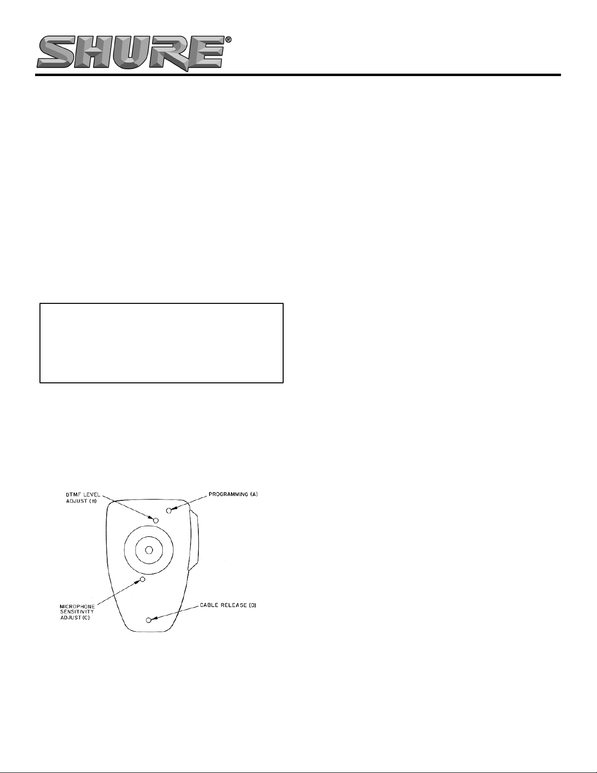
2. Remove the microphone cable by inserting the small
screwdriver supplied with the 890TT in rear case hole
“D” just above the cable jack (see Figure 1) to unlock
the plug, and withdrawing the plug from the jack.
FIGURE 1
3. Remove the four screws from the rear of the 890TT
case (see Figure 2).
4. Holding the 890TT with the rear toward you and the
cable connector downward, carefully remove the case
rear from the front. Note that the rear printed-circuit
board will either be retained in the case front when the
case rear is removed, or it may become disconnected
from these boards and remain attached to the case
rear. If the rear board is disconnected from the other
boards, all memory programming will be erased.
CAUTION: The middle board contains static-sensitive semi-
conductor devices that can be functionally damaged by handling. Make certain proper procedures are followed when
working with this board.
5. Carefully pivot the case rear to the right. Five wires
remain attached between the rear printed-circuit
board, the leaf switch, and the solder lug attached to
the case rear. When the rear board is disconnected
from the middle board (J301 removed from P101),
replacement of the rear board and leaf switch will be
simplified.
The following replacement instructions appear in the order
that each part or assembly is accessed.
RK268 CARTRIDGE-AMPLIFIER PC ASSEMBLY
To replace the cartridge-amplifier PC assembly (rear
board), follow these steps.
1. Remove the case rear as described above.
2. Carefully unsolder the four leads attached to the leaf
switch and the single lead attached to the case rear
solder lug. Observe the lead color connections for
proper terminal replacement.
3. Solder the leads of the replacement board to the
switch and case lug.
4. Make certain the microphone cartridge rubber resonator is properly aligned (rectangular section toward top
of microphone), and carefully guide the rear board
into its connection to the middle board (J301 into J201
and P101).
5. Carefully reassemble the case rear to the case front,
guiding the front pin of the push-to-talk button into the
round pivot recess of the case front. Reposition wires
as necessary to make certain none are pinched between the case halves. IMPORTANT: Make sure the
insulator linking the programming terminals on the
middle and rear boards (see Figure 2) is in place and
covering the terminal on both boards.
6. Replace the four screws and reinstall the 890TT.
RK271S LEAF SWITCH ASSEMBLY
To replace the leaf switch assembly, follow these steps.
1. Disassemble the case rear as described above.
2. Remove the push-to-talk button from the case rear.
3. Carefully unsolder the four leads from the leaf switch
assembly, noting the colors and terminals for proper
reattachment.
4. Unscrew the two No. 4–40 screws holding the switch
assembly to the case rear.
2002, Shure Incorporated
27B2501 (Rev. 1)
Printed in U.S.A.
Page 2
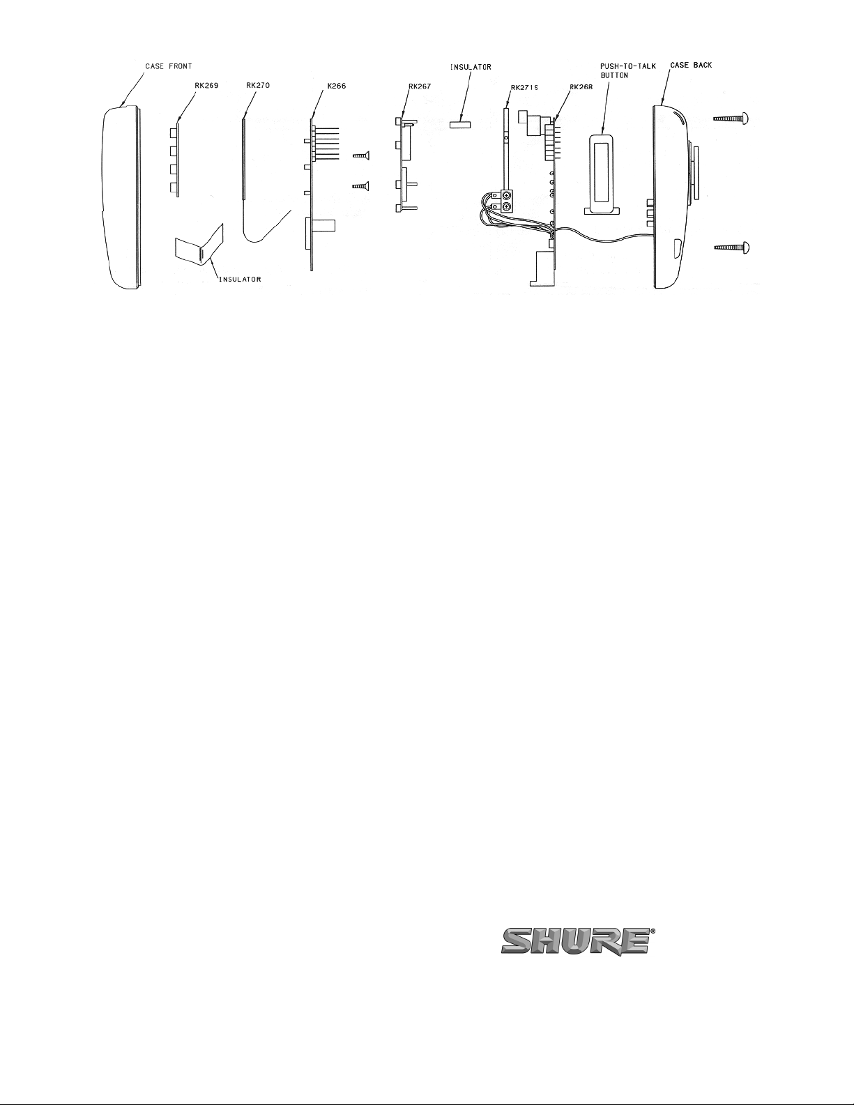
FIGURE 2
5. Carefully solder the four leads to the replacement
switch assembly.
6. Secure the replacement switch assembly with the two
screws previously removed.
7. Reassemble the microphone as described above.
RK267 DIGITAL PC ASSEMBLY
To replace the Digital PC Assembly (middle board), follow
these steps.
1. Remove the case rear and rear board as described
above.
2. Remove the ribbon cable by unlocking (sliding the top
cover approximately 1/16” downward) the ribbon
cable connector and gently withdrawing the cable.
Remove and retain the amber–colored ribbon cable
insulator.
3. Grasping two of the plastic standoffs, gently raise the
board upward, detaching it from the front board (J201
from P101).
4. Using proper static-sensitive device handling techniques, align connector J201 with P101 and press
downward on two of the standoffs to secure the
board.
5. Insert the ribbon cable in ribbon cable connector J203
and slide the cover upward to lock the cable in. Replace the ribbon cable insulator.
6. Reassemble the microphone as described above.
RK266 BATTERY–LED PC ASSEMBLY
To replace the Battery-LED PC Assembly (front board),
follow these steps.
1. Disassemble the microphone case and rear board as
described above.
2. Remove the middle board as described above.
3. Unscrew the two No. 4 screws holding the front board
to the case front.
4. Lift the front board up and out of the case front. The
membrane switch assembly may remain attached to
the front board or it may remain in the case front.
5. Remove the membrane switch assembly from the
front board if it is still attached, and seat the switch
assembly over the keypad.
6. Place the replacement front board over the membrane
switch assembly, thread the ribbon cable through the
slot in the board, and seat the board in the case front.
7. Secure the front board with the two screws previously
removed.
8. Reassemble the microphone as described above.
RK270 MEMBRANE SWITCH ASSEMBLY
To replace the membrane switch assembly, follow these
steps.
1. Disassemble the microphone case rear and board
assemblies as described above.
2. Separate the membrane switch assembly from the
front board if it is still attached.
3. Place the replacement membrane switch assembly in
the case front over the keypad.
4. Reassemble the microphone as described above.
RK269 KEYPAD
To replace the keypad, follow these steps.
1. Disassemble the microphone and board assemblies
as described above.
2. Remove the membrane switch assembly and keypad
from the case front.
3. Insert the replacement keypad in the case front.
4. Reassemble the microphone as described above.
SHURE Incorporated Web Address: http://www.shure.com
5800 W. Touhy Avenue, Niles, IL 60714-4608, U.S.A.
In U.S.A., Phone: 1-847-600-2000 Fax: 1-847-600-1212
In Europe, Phone: 49-7131-72140 Fax: 49-7131-721414
In Asia, Phone: 1-852-2893-4290 Fax: 1-852-2893-4055
International Fax: 1-847-600-6446
 Loading...