

Page 1

Model 888TT User Guide
GENERAL DESCRIPTION
The 888TT handheld, amplified, noise-canceling DTMF communications microphone is FAA Certified for aircraft application
(TSO-C58a). In addition to its extremely clear transmission, even
in noisy environments, the 888TT has very low sensitivity to hum
pickup and low susceptibility to radio frequency interference.
Audio and DTMF levels can be independently adjusted with the
supplied screwdriver to match the transmitter input gain. These
protected external controls prevent accidental changes by the user
while allowing adjustments without having to disassemble the microphone case.
The illuminated keypad is made of tough silicone rubber, with
durable printed characters that will last the life of the microphone.
The keypad is backlit by red LEDs, easily visible during night operation, minimizing eye readjustment for night vision.
The 888TT may be used with most currently available aircraft
radios. For convenience, all microphone and signaling functions,
including keypad illumination, are powered directly from the microphone input circuit of most transmitters, reducing the need for
equipment modification. A five-conductor MODULINK
separately) connects the modular telephone-type socket of the
888TT to most aircraft radios using a PJ-068 plug. This cable can
be instantly changed or replaced without soldering.
The 888TT is ergonomical, fitting naturally and comfortably in
the hand. The voice-entry port is at the top of the microphone body
for simple, natural transmitting. The microphone is not affected by
heat or humidity, and the rugged ARMO-DUR
oil, grease, most fumes and solvents, salt spray, sun, rust and corrosion. The 888TT is outstanding in its ability to withstand mechanical shocks and vibration. Its Million-Cycle Plus™ leaf-type switch
is a double-pole, single-throw type that resists the effects of severe
operating conditions and constant use. It has nickel-silver blades
with palladium alloy contacts for reliable oxidation-free operation.
The microphone is supplied with output levels factory preset to
meet TSO-C58a requirements. Adjustments should be made only
by an FAA Approved Service Facility or the Shure Service Department.
The 888TT is supplied with a small screwdriver for releasing the
modular-plug microphone cable from the case and for adjusting
the microphone amplifier gain and DTMF level. A mounting loop is
supplied affixed to the microphone, and mounting brackets for attaching to radio equipment or other surfaces are available in quantities of three as Shure RK6MB.
®
cable (sold
®
case is immune to
PART OF A COMPLETE LINE
The 888TT is part of a full line of mobile microphones, circuitry products and related accessories.
For a complete listing, contact your Shure Representative or visit www.shure.com.
APPLICATIONS
•
Aerospace
FEATURES
•
FAA CERTIFIED FOR AIRCRAFT USE
•
DETACHABLE MODULINK® MODULAR PLUG COIL CORD
WITH PJ-068 AIRCRAFT-RADIO PLUG OR A4M TYPE
CONNECTOR
•
NOISE-CANCELING WITH FREQUENCY RESPONSE
TAILORED FOR OPTIMUM INTELLIGIBILITY
•
TOP-TALK SOUND CHANNEL™ FOR CLEAR VOICE INPUT,
EASY HANDLING
•
BUILT-IN TRANSISTOR AMPLIFIER POWERED BY
CARBON-MICROPHONE-TYPE CIRCUIT
•
ILLUMINATED KEYPAD WITH POSITIVE TACTILE
CONFIRMATION AND AUDIBLE VERIFICATION TONES
•
SIMPLE EASY-TO-USE CONTINUOUS-TONE DIALING
•
SCREWDRIVER ACCESSIBLE DTMF LEVEL ADJUSTMENT,
INDEPENDENT OF MICROPHONE GAIN SETTING
•
LOW SENSITIVITY TO HUM AND RF INTERFERENCE
•
RUGGED MILLION-CYCLE PLUS™ LEAF-TYPE SWITCH
STANDS UP UNDER SEVERE ENVIRONMENTS AND
CONSTANT USE
•
HIGH IMPACT ARMO-DUR® CASE, STRONG,
LIGHTWEIGHT, COMFORTABLE TO THE TOUCH IN HOT
OR COLD ENVIRONMENTS
•
RUGGED AND DEPENDABLE UNDER ALL OPERATING
CONDITIONS
SET-UP
The 888TT is equipped with a hang-up loop and a rear-case hang-up button for use with a mounting bracket on associated equipment.
Heavy-duty chrome-plated mounting brackets are available in quantities of three as Shure Part No. RK6MB.
CONNECTIONS
To attach the cable to the 888TT, insert the modular telephonetype plug in the microphone jack until it locks.To remove the cable
from the microphone, insert the small screwdriver supplied with the
888TT in case hole “A” just above the cable jack (see Figure 4) to
unlock the plug and withdraw the plug from the jack. Microphone
connector wiring is shown in the table below. The ALM-88 cable is
wired at the microphone connector as shown in Figure 3.
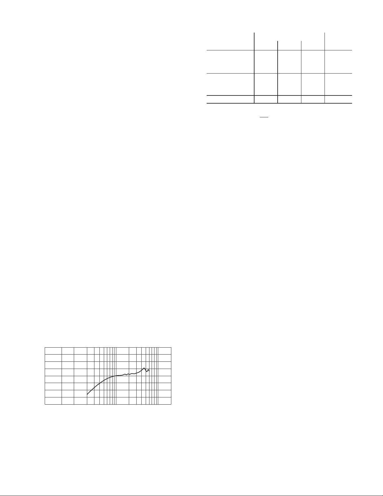
Table 1. Microphone Connector Wiring
Pin
Color Function Pin Color Function
1 N.C. 5 Black PTT
2 White Dc Bias (+),
3 Yellow PTT Switch 7 Drain Ground
4 Blue NC 8 N.C.
Audio Out
6 Red Audio Out
Switch
Ground
(Ac
coupled)
©2004, Shure Incorporated
27A6003B (Rev. 2)
®Shure, MODULINK, and ARMO-DUR are registered trademarks of Shure,
Incorporated.™ Million-Cycle Plus and Top-talk Sound Channel are trademarks of
Shure Incorporated. All other trademarks are the property of their respective owners.
Printed in U.S.A.
Page 2
OPERATION
Voice Transmission
1. Hold the microphone comfortably in the hand positioned so
that the Top-Talk Sound Channels™ at the top of the case are
near the mouth.The clearest sound is often obtained with the
microphone at the corner of the mouth, with the cable away
from the face.
2. Depress the push-to-talk button and make sure the equipment is in the transmit mode before speaking.
Dialing
1. Press and hold the push-to-talk button.
2. Press the desired keypad buttons in sequence.A high-pitched tone will confirm that the code has been transmitted. (The microphone audio is muted during DTMF tone transmission.)
Operation of microphone and DTMF functions requires that the 888TT be connected to the communications equipment and that the equipment power is turned on.
After connection to the communications set, turn the equipment
power On. Pressing the push-to-talk switch and observing the keypad LED backlighting can verify power application.
Factory preset microphone audio and DTMF levels are correct
for aircraft radios with standard input circuits (as defined in RTCA
DO-170), and level adjustment should not ordinarily be necessary.
When such adjustment is necessary, it should be performed only
by Shure Incorporated or by an FAA Approved Service Facility.
Use the supplied screwdriver to adjust the microphone sensitivity and DTMF output levels as follows:
1. Microphone sensitivity: Press the push-to-talk button and
speak normally into the microphone while checking transmitter
modulation.Adjust the microphone sensitivity control (case
back, hole “B” in Figure 4) and repeat the talk test as required.
2. DTMF output: Press and hold the push-to-talk button.
Depress and hold down a keypad button for a continuous
tone. Adjust the DTMF output control (case back, hole “C” in
Figure 4) as required.
Electrical Characteristics
Operating Voltage
8 V 12 V 28 V Notes
Audio Output Level*
(100 µbar acoustic
test signal at
1 kHz, 10 mm)
DTMF Output Level
Dc Supply Current**
*Standard electrical test circuit per RTCA DO-170
**Microphone is powered only
current = 0 if PTT switch is released)
–11.5 dBV
(266 mV)
–12.8 dBV
(230 mV)
6 mA 12 mA 36 mA
–11.0 dBV
(281 mV)
–12.0 dBV
(250 mV)
while PTT switch is depressed (standby
–10.0 dBV
(316 mV)
–11.2 dBV
(275 mV)
Audio trimpot in factory
preset position
DTMF trimpot in factory
preset position
Environmental Conditions
Operating Temperature: -40 to 60° C (-40 to 140° F)
Storage Temperature: -54 to 85° C (-65 to 185° F)
Relative Humidity: 0 to 95% (non-condensing)
Microphone Connector
6-conductor modular telephone type
PTT Switch Assembly
Mechanical: Double-pole, single-throw, leaf-type, normally open
Cable
ALM-88, detachable MODULINK
®
, 1.8 m (6 ft) extended cord
with modular plug on microphone end and PJ-068 aircraft connector on equipment end; and ALM-89 with A4M type connector.
Construction
Case: Black textured high-impact ARMO-DUR
Switch Button: Black ARMO-DUR
®
®
Keypad: Molded silicone rubber
Hang-up Loop: Matte finish stainless steel
Dimensions
See Figure 2
Net Weight (including cable and connector)
283 g (10 oz)
Replacement Parts
Modular plug-cable with PJ-068 plug assembly.. ALM-88
A4M type connector............................................ALM-89
SPECIFICATIONS
Type
Electret condenser, noise canceling, with transistor pre-amplifier, DTMF signaling circuitry, illuminated keypad
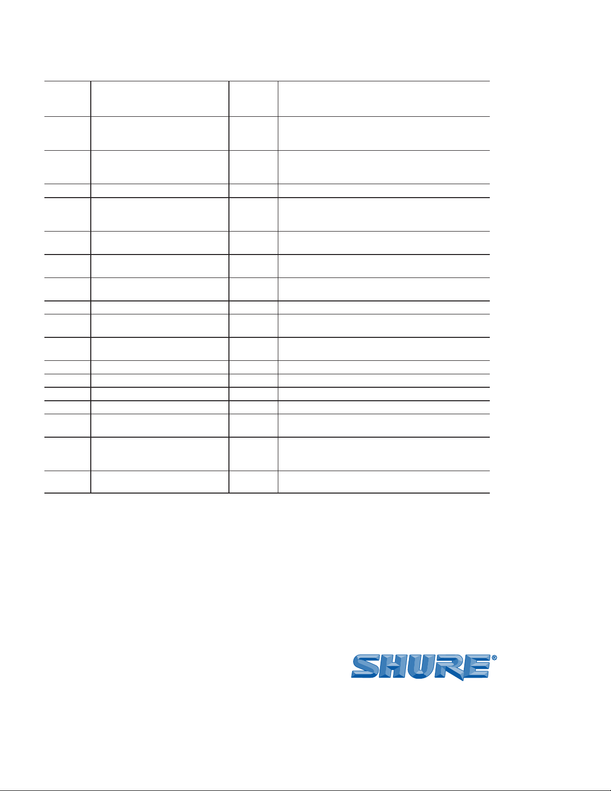
Frequency Response
200 to 4,000 Hz (see Figure 1)
+10
0
dB
±10
500 1,000 2,000 5,000 10,000 20,00050 100 20020
TYPICAL FREQUENCY RESPONSE
Polar Pattern
Bidirectional, noise canceling
Hz
FIGURE ONE
Furnished Accessories
Screwdriver......................................................... 80B498
Optional Accessories
Mounting Bracket (3 in kit) .................................. RK6MB
FAA Certification
The Model 888TT is FAA Certified for aircraft use under FAA
TSO-C58a requirements. To maintain this FAA Certification, any
service required for the Model 888TT must be performed by Shure
Incorporated or by an FAA Approved Service Facility.
2
Page 3

Warranty
Shure Incorporated (“Shure”) hereby warrants that this product
will be free in normal use of any defects in materials and workmanship for a period of one year from the date of purchase for all cartridge and housing assembly parts and for a period of one year
from the date of purchase for all transmitter parts. At its option
Shure will repair or replace the defective product and promptly return it to you, or refund the purchase price. You should retain proof
of purchase to validate the purchase date and return it with any
warranty claim. If you believe this product is defective within the
warranty period, carefully repack the unit, insure it and return it
postage prepaid to:
Shure Incorporated Attention: Service Department 5800 W. Touhy Avenue Niles, IL 60714-4608 U.S.A.
Outside of the United States, return the product to your dealer or Authorized Service Center.
This warranty does not apply in cases of abuse or misuse of the
product, use contrary to Shure’s instruction, ordinary wear and
tear, an act of God or unauthorized repair. All implied WARRANTIES OF MERCHANTABILITY or FITNESS FOR A PARTICULAR
PURPOSE are hereby disclaimed and Shure hereby disclaims liability for incidental, special, or consequential damages resulting
from the use or unavailability of this product. Some states do not
allow limitations on how long an implied warranty lasts, or the exclusion or limitation of incidental or consequential damages, so the
above limitation may not apply to you. This warranty gives you specific legal rights, and you may have other rights which vary from
state to state.
THIS WARRANTY SUPERSEDES ALL OTHER WARRANTIES THAT ARE ASSOCIATED OR INCLUDED WITH THIS PRODUCT.
FIGURES
1.9 mm
(5/64 IN.)
40.4 mm
(1-19/32 IN.)
44.4 mm
(1-3/4 IN.)
42.6 mm
(1-11/16 IN.)
25.4 mm
(1 IN.)
64 mm
(2-1/2 IN.)
70 mm
(2-3/4 IN.)
OVERALL DIMENSIONS
FIGURE TWO
36.9 mm
(15/32 IN.)
101 mm
(3-31/32 IN.)
DRAIN
RED
BLACK
BLUE
YELLOW
WHITE
RJ11 CONNECTOR (TO MICROPHONE)
DRAIN
RED
BLACK
BLUE
YELLOW
WHITE
NC
NC
MODULINK CABLE WIRING
FIGURE THREE
DTMF LEVEL
ADJUST (C)
MICROPHONE
SENSITIVITY
ADJUST (B)
CABLE
RELEASE (A)
MICROPHONE CASE BACK
FIGURE FOUR
SLEEVE (GROUND)
RING (AUDIO)
TIP (PTT)
PJ-068 CONNECTOR (TO RADIO)
3
Page 4
ENVIRONMENTAL QUALIFICATION FORM,TSO-C58A
ENVIRONMENTAL QUALIFICATION FORM, TSO-C58a
DO-170
PARA. #
CONDITIONS
3.1.1 Ground Survival Low Temperature and Operating Low Temperature
3.1.2 Ground Survival High Temperature and Short-Time Operating High Temperature
Operating High Temperature 4.5.3 Microphone tested to Category D1
3.1.3 Altitude 4.6.1 Microphone tested at altitude equivalent to
3.1.4 Decompression 4.6.2 Microphone tested at altitude equivalent to
3.1.5 Overpressure 4.6.3 Microphone tested at pressure = 170 kPa; equiv-
2.11 &
3.2
Temperature Variation – Preamplifier
3.3 Humidity 6.3.1 Microphone tested to Category A for 2 cycles.
3.5 Vibration 8.5 Microphone tested to Categories N, B, & M
3.6 Magnetic Effect 15.3 Microphone tested to Equipment Class Z; no
3.7 Voltage Spike Conducted 17.3 Microphone tested to Category A
3.8.1 Induced Signal Susceptibility* 19.3 Microphone tested to Category Z
3.9 Radiated rf Susceptibility*† 20.5† Microphone tested to Category A
3.10 Emission of rf Energy* 21.4 Microphone tested to Category Z
3.11 Final Distortion After all required environmental tests micro-
3.12 Push-To-Talk Switch Life After all required environmental tests micro-
Fire Retardance In accordance with FAR 25; 25.869(a)(4) and
*Tests performed at Radiometrics Midwest Corporation,
Lombard, IL
†Tested to DO-160B
**Tests performed at Elite Electronic Engineering,
DO-160C
PARA. #
DESCRIPTION OF TESTS
4.5.1 Microphone tested to Category D1
4.5.2 Microphone tested to Category D1
15,200 m (50,000 ft) = 11.6 kPa (116 mbar, 87
mm [3.42 in.] Hg)
15,200 m (50,000 ft)
alent altitude = –15,000 ft
5.3 Microphone tested to Category B for two cycles.
(Table 8-1, Not on Vibration Isolators)**
magnetic properties
phone meets requirements of DO-170, 2.2
phone meets requirements of DO-170, Appendix
B, T-7 and 2.9
Appendix F, Part I (a)(3)(b)***
Downers Grove, IL
***Tests performed at Gaynes Test Laboratories,
Chicago, IL
All other tests performed at Shure Inc., Evanston, IL
INFORMATION TO USERS ———————————————————————
This equipment has been tested and found to comply with the
limits for a Class B digital device pursuant to Part 15 of the FCC
Rules. These limits are designed to provide reasonable protection
against harmful interference in a residential installation. This
equipment generates, uses, and can radiate radio frequency energy, and, if not installed and used in accordance with the instructions, may cause harmful interference to radio communications.
However, there is no guarantee that interference will not occur in a
particular installation.
If this equipment does cause harmful interference to radio or
television reception, which can be determined by turning the equipment off and on, the user is encouraged to try to correct the interference by one or more of the following measures:
•
Reorient or relocate the receiving antenna.
•
Increase the separation between the microphone and receiver.
•
Connect the microphone transmitter into an outlet on a circuit
different from that to which the receiver is connected.
Consult the dealer or an experienced radio/TV technician for
help.
SHURE Incorporated Web Address: http://www.shure.com
5800 W. Touhy Avenue, Niles, IL 60714-4608, U.S.A.
In U.S.A., Phone: 1-847-600-2000 Fax: 1-847-600-1212
In Europe, Phone: 49-7131-72140 Fax: 49-7131-721414
In Asia, Phone: 1-852-2893-4290 Fax: 1-852-2893-4055
International Fax: 1-847-600-6446
4
 Loading...