

Page 1
222
HARTREY
AVE
.
EV:NSTON.
ILL
-
CABLE
SHUREMICRO
-
I-
MICROPHONES AND
EVANSTON PHONE
DA
ELECTRONIC
8.9000
CHICAGO
COMPONENTS
PHONE
SH
3.1600
DATA
I
SHEET
Model
81
5
and
Model
816
I
Magnetic Tape Recordinq Heads
General:
ing Heads are high quality recording units designed for use with
paper and
places Shure Manufacturers Model Numbers TR5,
TR5H. Model 816 replaces Shure Manufacturers Model Numbers
TR6C and TRbE.
Model 815 Recording Head comjines the functions of recording, playback and signal erasure
Recording Head is a record and playback unit only.
Applications:
able for use in all types of tape recording and playback applica-
tions-the professional,
The recording heads are of rugged construction and immune to
practically all effects of moisture, tenperature and mechanical vibrations. The carefully contoured and highly polished surfaces give
uniform response, long operating life, and (in case of the Model
8
15) high erase efficiency.
The outer metal cases are
excellent hum shielding, which minimizes the
Ins*alla+ion:
mounted by clamping the recording head at the center top of the
metal case or at the flanged edges. Positioning pins through the
center of the eyelets may be used to accurately locate
ing head on the mechanism. Care
ing or distorting of the
of hum shielding effectiveness. Dimensional data is given in
Figure
Care must also be taken to position the heads so that the re-
cording-playback gap is perpendicular to the length of the tape.
This is especially important in using pre-recorded tapes. The Model
815 is assembled in such a manner as to insure that the recording
gap is perpendicular within
bosses. When properly installed, tho mounting bosses of the recording head should seat on a mounting surface parallel to the
direction of travel of the tape. To insure perpendicularity, the
mounting bosses on some heads are shimmed with a thin tab of
metal held by the eyelets on one side of the head. Deforming or
removing this tab destroys the alignment between gap and mounting bosses.
The Model 815
of positioning and
Some external
user in adjusting the tape
ing surface. Also, by proper location of the tape guide, the tape
will enter and leave the recording surface at the correct angle.
See Figure C for information on tape guides and tape angles.
To insure proper contact of the tape against the recording surface of the head, pressure pads may be used. The pressure pads
are made of felt
on small metal arms, which are held against the recording head
b
springs adjusted to the force indicated in Figure
a%o, shows a suggested layout for pressure pad arrangement.
The Model 816 Tape Recording Head does have a means of
positioning and guiding the tape across the recording
a groove to properly locate the recording tape has been machined
and polished into the recording surface. In this case, the unit is
assembled in such a manner as to insure that the recording gap
is perpendicular within,
TAPE GUIDE GROOVE. Proper contact of the tape against the
recording surface may be insured by use of a pressure pad. Figure
C,
also, shows tape angle and pressure pad arrangement for the
Model 816.
Model 815 and Model 816 Magnetic Tape Record-
plastic base magnetic recording tapes. Model 815 re-
In
a single unit. Model 816
Both the Model 815 and Model 816 are suit-
semi-professional and home-recording types.
high permeability shields and afford
of hum producing components.
The Model 815 and the Model 816 may be
metal shield, which wouid result in loss
mtist be taken to prevent bend-
TRBA, TR5D and
~roblem of mechanical
the record-
B.
&
Y20
to the surface of the mounting
Tape Recording Head does not have a means
guiding the tape across the recording surface.
guides will be required. These guides assist the
1
/
parallel to the recording head mount-
16"
thick by
1/4"
square. The pads are mounted
C.
2
Y2"
to the BOTTOM EDGE OF THE
Figure
surface-
C,
L-
-
b
-
I,,;d
Model
815
Model 816
A
FIG. A CIRCUIT DIAGRAMS
RECORD
AND
PLIIBLCK
COlL
1LYL
ItD
011*61
L5\0
,MD
,."X,.,,O"
'
,SAD
MODEL
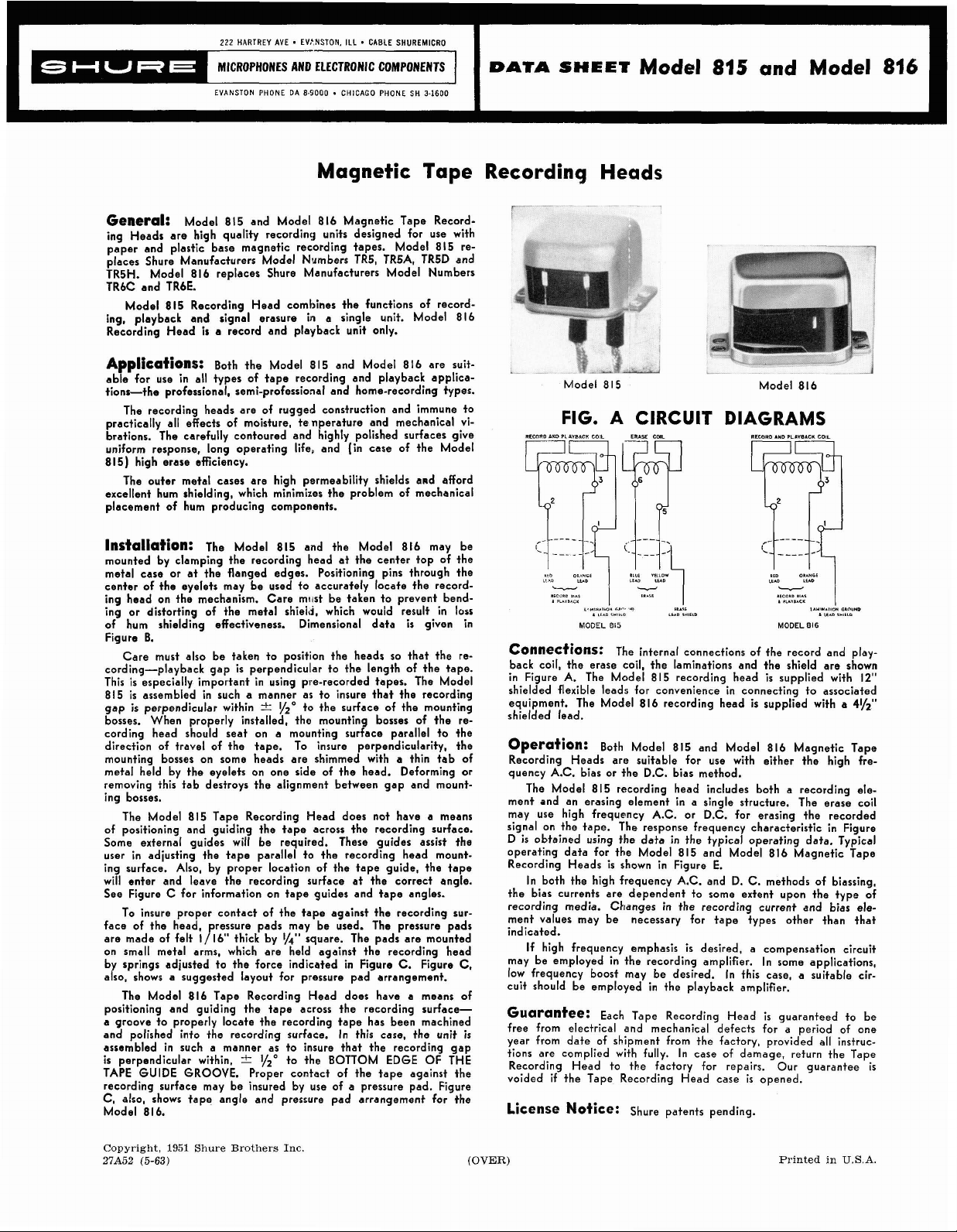
C~nne~ti~nS:
back coil, the erase coil, the laminations and the shield are shown
in Figure
shielded flexible leads for convenience in connecting to associated
equipment. The Model 816 recording head is supplied with a
shielded lead.
Operation:
Recording Heads arc suitable for use with either the high fre-
quency A.C. bias or the D.C. bias method.
ment and an erasing element in a single structure. The erase coil
may use
signal on the tape. The response frequency characteristic in Figure
D is obtained using the data in the typical operating data. Typical
operating data for the Model 815 and Model 816 Magnetic Tape
Recording Heads is shown in Figure E.
the bias currents are dependent to some extent upon the type of
recording media.
ment values may be necessary for tape types other than that
indicated.
may be employed in the recording amplifier. In some applications,
low frequency boost may be desired. In fhis case, a suitable circuit should be employed in the playback amplifier.
Guarantee:
free from electrical and mechanical defects for a period of one
year from date of shipment from the factory, provided all instructions are complied with fully. In case of damage, return the Tape
Recording Head
voided if the Tape Recording Head case is opened.
A.
The Made1 815 recording head is supplied with 12"
Both Model 815 and Model 816 Magnetic Tape
The Model 815 recording head includes both a recording ele-
high frequency A.C. or D.C. for erasing the recorded
In both the high frequency A.C. and D. C. methods of biassing,
If
high frequency emphasis is desired, a compensation circuit
Each Tape Recording Head is guaranteed to be
License Notice:
"11101
e"
."
,"<k,O
815
The internal connections of the record and play-
S..,&
LEAD
,",eLD
RID
LEAD
MODEL
O.*NLT
-0
l."I*.110*
TIOUND
1
LEAD
,*,EL0
816
4%"
Changes in the recording current and bias ele-
to the factory for repairs. Our guarantee is
Shure patents pending.
1
Copyright,
27A52
(5-63)
1951
Shure Brothers
Inc.
(OVER)
Printed in
U.S.A.
Page 2
MODEL
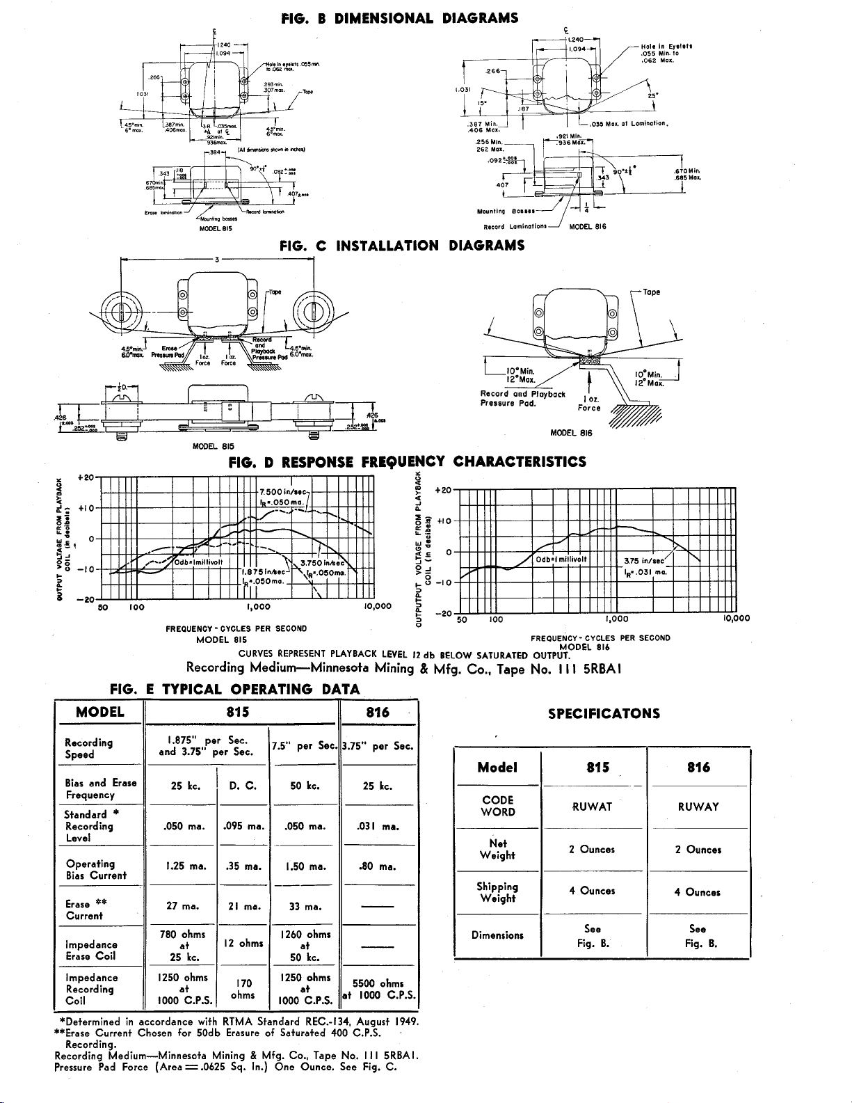
FIG. B DIMENSIONAL DIAGRAMS
815
C INSTALLATION DIAGRAMS
FIG.
D
RESPONSE FREQUENCY CHARACTERISTICS
I
t
2;
s
z
e
B
g5t
4
-1
g
a
0
I-
s
8
t
20
+I0
-10
-20
FREQUENCY - CYCLES PER SECOND
MODEL 815
CURVES REPRESENT PLAYBACK LEVEL
Recording Medium-Minnesota Mining & Mfg. Co., Tape
FIG. E TYPICAL OPERATING DATA
MODEL
Recording
Speed
Bias and Erase
Frequency
Standard
Recording
Level
Operating
Bias Current
Erase
Current
Impedance
Erase Coil
Impedance
Recording
Coil
*Determined in accordance with RTMA Standard REC.-134, August 1949.
**Erase Current Chosen for 50db Erasure of Saturated 400 C.P.S.
Recording.
Recording Medium-Minnesota Mining
Pressure Pad Force (Area = .0625
*
**
and
1.875"
3.75,,
25
.050 ma.
1.25 ma.
27 ma.
780 ohms
25 kc.
1250 ohms
at
1000 C.P.S.
kc.
per
per
/
81
5
Sec.
D.
.095 ma.
.35 ma.
-
21 ma.
I2
7.5" per Sec.
Set.
C.
50 kc.
.050 ma.
1.50 ma.
---
33 ma.
ohms
Sq.
1260 ohms
at
50 kc.
1250
at
1000 C.P.S.
&
Mfg. Co., Tape No.
In.) One Ounce. See Fig.
ohms
816
3.75" per Sec.
25 kc.
.031 ma.
.80 ma.
-
-
5500 ohms
at
I0O0
C.P.S.
I I
I
5RBAI.
C.
12
db
BELOW SATURATED OUTPUT.
Model
CODE
WORD
Net
Weight
Shipring
We~ght
Dimensions
1,000
FREQUENCY - CYCLES PER SECOND
MODEL 816
No.
I I
I
5RBAI
SPECIFICATONS
81
5
-
RUWAT
2 Ounces
4 Ounces
See
Fig. B.
10,o
81 6
RUWAY
2 Ounces
4 Ounces
See
Fig. B.
 Loading...