

Page 1
222 HARTREY AVE.. EVANSTON. IL. 60204 U.S.A.
D
I
@r
MICROPHONES
AREA
CODE 312/866-2200 CABLE:
TWX: 910-231-0048 TELEX: 72-4381
AND ELECTRONIC
COMPONENTS
SHUREMICRO
1
DATA
SHEET
1
MODEL
711
LOUDSPEAKER SYSTEM
VARADTM AND SIT EQUIPPED
I
OPERATION AND SERVICE INSTRUCTIONS
DESCRIPTION
The Model 71 1 Professional Loudspeaker System
consists of an all-new Shure-designed and
-manufactured 15-inch
a Shure-designed and -manufactured high-power highfrequency driver, and a unique
dispersion horn with sliding vanes to set 60°, 90° Left,
90° Right, or 120° coverage angles. The Model 711
Speakers can be used individually or in combination to
provide high-SPL sound reinforcement of wide frequen-
cy range program material in any shape or size of
room-from the most intimate club to the largest
auditorium.
The 711 system has a frequency response of 56 to
14,000 Hz and an impedance of 8 ohms. The system is
designed to operate with amplifiers capable of deliver-
ing up to 150 watts continuous to an
range operation and up to 200 watts low-frequency
when biamplified. The 711
that automatically converts to biamplif ied operation. In
addition, two low-frequency
parallel-wired to permit cascading speakers as well as
connecting each speaker to a separate amplifier output.
The 711 has built-in passive low-frequency and highfrequency crossover networks for optimum acoustic
matching and speaker protection.
overload protection circuit safeguards the highfrequency driver against damage from unusually high-
level signals.
The speaker system is housed in a front-vented
Thiele-Small aligned bass reflex cabinet constructed of
(5/s
15.9 mm
resistant black vinyl, with steel corner protectors and
durable plastic feet. A handsome metal grille that protects the woofer can be easily removed or permanently
attached (see page 2). The 71 1 weighs 30 kg (66 Ib) and
can be carried by grasping it at the top and sides of the
cabinet corners. Proper lifting techniques should be
observed when handling equipment of this size and
weight.
A heavy-duty 15m (50 ft), 18-gauge, rubber-jacketed
connecting cable with phone plugs is supplied with the
speaker. A rugged vinyl slip-on protective cover with a
Copyright
27A8006(AH)
1981,
in.) plywood, covered in strong, scuff-
Shure Brothers
Shure Music Transducer
VARADTM variable-
&ohm load for full-
features a switching jack
andlor full-range jacks are
In
Inc.
woofer,
addition, an
cable pocket is available as Model A711C.
SPECIFICATIONS
Power Rating
Maximum recommended amplifier output to 8 ohms:
Full Range: 150 watts continuous, 34.6 Vrms, 55V
peak;
Biamplified-Low Frequency: 200 watts continuous,
40 Vrms,
continuous, 34.6 Vrms, 55V peak.
Frequency Response
56 to 14 kHz k5 dB (see Figure 1)
TYPICAL
Impedance
8 ohms rated (see Figure 2)
Crossover Frequency
2 kHz; low frequency: 12 dBloctave;
63.5V peak; High Frequency: 150 watts
'/3
OCTAVE FREQUENCY RESPONSE
(HORN SET AT
FIGURE
FREOUENN
TYPICAL IMPEDANCE
FIGURE
high frequency: 18 dBloctave
120')
1
IN
HERTZ
2
Printed
in
U.S.A.
Page 2
Sound Pressure Level
101 dB at
1m with 1W input (2.83V)
Phasing (polarity)
Positive voltage on phone jack tip produces positive
sound pressure (woofer cone moves out)
High Frequency Section
120°, 90°L, 90°R, or 60° (selectable) radial horn;
High-power driver,
1 %-inch voice coil
Low Frequency Section
15-inch SMT woofer,
2lh-inch voice coil
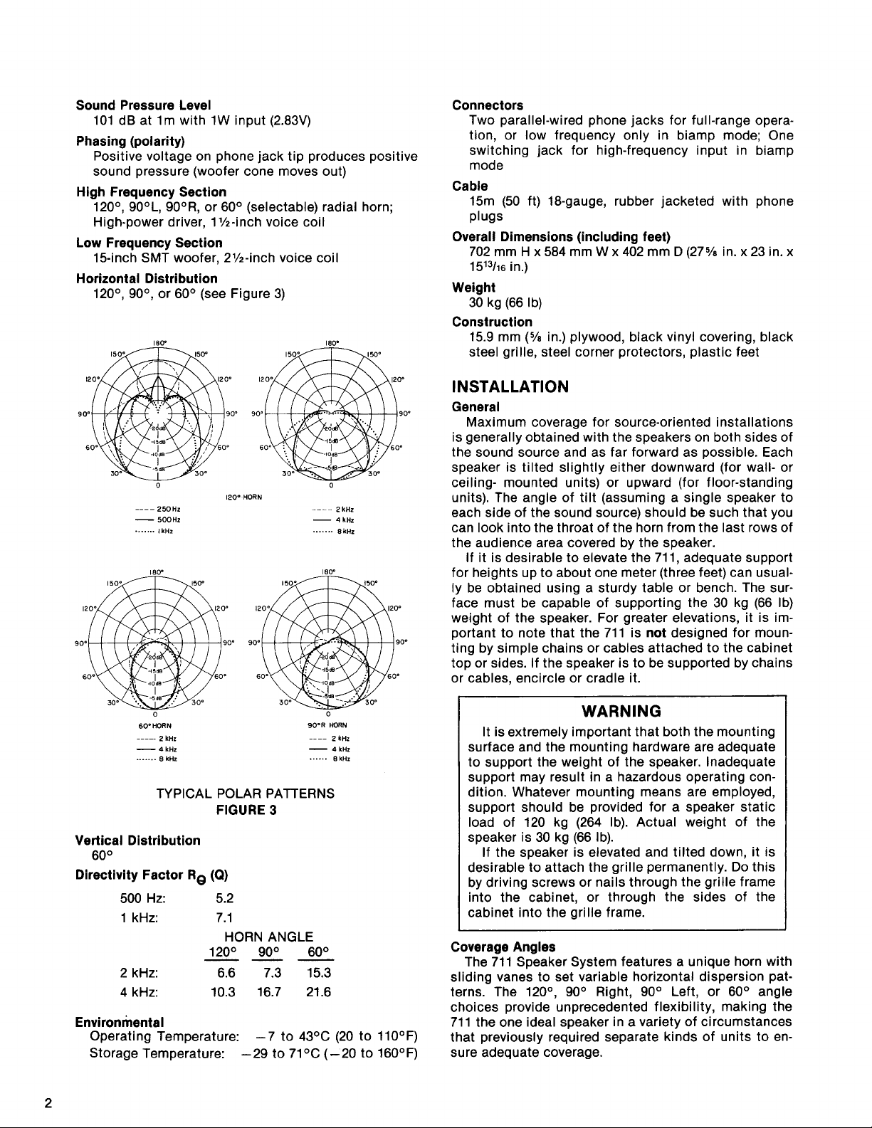
Horizontal Distribution
120°, 90°, or 60° (see Figure 3)
HORN
----
-
.......
0
2 kHz
4
kHz
8
kHz
Connectors
Two parallel-wired phone jacks for full-range operation, or low frequency only in biamp mode; One
switching jack for high-frequency input in biamp
mode
Cable
15m (50 ft) 18-gauge, rubber jacketed with phone
plugs
Overall Dimensions (including feet)
702
mm H x584 mm W x 402 mm D(27% in. x23 in. x
1513/16 in.)
Weight
30 kg (66 Ib)
Construction
mm
(%
15.9
in.) plywood, black vinyl covering, black
steel grille, steel corner protectors, plastic feet
INSTALLATION
General
Maximum coverage for source-oriented installations
is generally obtained with the speakers on both sides of
the sound source and as far forward as possible. Each
speaker is tilted slightly either downward (for wall- or
ceiling- mounted units) or upward (for floor-standing
units). The angle of tilt (assuming a single speaker to
each side of the sound source) should be such that you
can look into the throat of the horn from the last rows of
the audience area covered by the speaker.
If it is desirable to elevate the 711, adequate support
for heights up to about one meter (three feet) can usually be obtained using a sturdy table or bench. The surface must be capable of supporting the 30 kg (66 Ib)
weight of the speaker. For greater elevations, it is im-
portant to note that the 711 is not designed for moun-
ting by simple chains or cables attached to the cabinet
top or sides. If the speaker is to be supported by chains
or cables, encircle or cradle it.
90DR
6O'HORN
.....
-
.......
2
kHz
4
kHz
8
kHz
..--
-
......
HORN
2
4
8
kHz
kHz
kHz
TYPICAL POLAR PATTERNS
FIGURE
3
Vertical Distribution
60°
Directivity Factor Re
(Q)
500 Hz: 5.2
1 kHz: 7.1
HORN ANGLE
120° 90° 60°
---
2 kHz: 6.6 7.3 15.3
4 kHz:
10.3 16.7
21.6
Environmental
Operating Temperature: -7 to
43OC (20 to llO°F)
Storage Temperature: -29 to 71°C (-20 to 160°F)
WARNING
It is extremely important that both the mounting
surface and the mounting hardware are adequate
to support the weight of the speaker.
support may result in a hazardous operating condition. Whatever mounting means are employed,
support should be provided for a speaker static
load of 120 kg (264 Ib). Actual weight of the
speaker is 30 kg (66 Ib).
If the speaker is elevated and tilted down, it is
desirable to attach the grille permanently. Do this
by driving screws or nails through the grille frame
into the cabinet, or through the sides of the
cabinet into the grille frame.
Coverage Angles
The 71 1 Speaker System features a unique horn with
sliding vanes to set variable horizontal dispersion patterns. The
120°, 90° Right, 90° Left, or 60° angle
choices provide unprecedented flexibility, making the
711 the one ideal speaker in a variety of circumstances
that previously required separate kinds of units to ensure adequate coverage.
Inadequate
Page 3

Adjust the angle by sliding the vane all the way out or
all the way in. With both vanes out, the speaker is set for
120°; with both vanes in, for 60°; with the right vane in,
90° left; and with the left vane in, for 90° right. (To
for
narrow the angle, slide the vane in; to widen it, slide the
vane out.)
Setting the horn at
60° concentrates the high-
frequency energy in an area one half that of a 120° horn.
3
This concentration produces an approximately
dB increase in the high-end response for "long throw" applications. The extra high-end energy is extremely
useful in providing maximum intelligibility for speech
and singing voices, or in penetrating where acoustics
are "dead" or where singers' voices must compete with
loud amplified instruments on stage.
Use the
in "short throw" applications. Use the
"off center" or
120° angle for coverage of short, broad areas,
90° angles for
'I"-shaped applications. The 60° and 90°
positions are also extremely useful when several
speakers are employed to cover individual sectors of a
very large hall or outdoor stadium.
Figure 4 illustrates the coverage angles, areas, and
sound pressure levels of the
VARADTM horn in the 711
Speaker System.
HORN 120'
1'01$,"'1
HOOKUP
Amplifiers
The 71 1 is designed for use with the Shure Models
700 or 706 Power Consoles and similar amplifiers having the following maximum power output capabilities.
Speaker Wiring
Fifteen meters (50 ft) of cable is supplied with each
711 Speaker System. For convenient attachment, a
straight phone plug and a right-angle phone plug are
provided. Connect either end to the back of the speaker
and to the Power Console amplifier. The supplied cable
is 18 gauge (No. 18 AWG) and can be used for cable runs
of up to 15m (50 ft) between the speaker and the
amplifier. If cable runs longer than
use the following table to determine the correct wire
gauge.
Maximum
Distance From
Power Console
Amplifier Wire Gauge Recommended Cables
15m are required,
HIGH-FREQUENCY COVERAGE: ON-AXIS SPL
INCREASES AS ANGLE DECREASES
COVERAGE ANGLES
FIGURE
4
If two speakers are stacked for source-oriented installations, horn-to-horn mounting with horns angled
apart to cover separate areas will provide the best
sound dispersion pattern. For stacked and splayed
speakers, the
Judicious speakerlmicrophone placement
60° horn angle is recommended.
andlor the
use of equalization or feedback filters in the sound
system will often relieve acoustic feedback. In addition,
narrowing the horizontal dispersion angle from
120° to
90° or 60° can be effective in remedying high-frequency
feedback conditions, when, for instance, speakers on
stage have dispersion patterns that overlap the pickup
areas of open microphones.
15m (50 ft) AWG 18 Belden
#8460, #8461,
#9470, #8542
30m (1 00 ft) AWG 16 Belden #8470, #8471,
#8472
60m (200 ft) AWG 14 Belden #8473
Preferably, each speaker should be connected to a
separate amplifier output jack to minimize power losses
in the cable. Two parallel-wired Low
FrequencylFull
Range jacks are provided on the back of each 711
Speaker System. This allows connecting two speakers
by connecting the first speaker to the amplifier and the
second speaker to the first. This may be helpful in certain room shapes. However, when speakers are connected in this manner, the next heavier wire gauge is
recommended between the amplifier and the first
speaker. Therefore, for two speakers connected
together where the first is at a distance of 30m (100 ft)
from the amplifier, use No. 14 AWG cable between the
amplifier and the first speaker; for two speakers where
the first is at 15m (50 ft), use No. 16 AWG cable between
the amplifier and the first speaker. When positioning
the speaker cables, place them where the audience, performers, or passers-by will not trip over them.
To avoid frequency response aberrations, poor
coverage, and dead zones caused by improper speaker
phasing in multiple speaker installations, all speakers
must be wired with the same polarity. The cables listed
in the chart above are color-coded to ensure that identical connections are used. Note that even common
18-gauge lamp cord ("zip" cord) is phase-coded with ribs
along the outer jacket of one conductor.
Page 4

The cable can be stored in the convenient snap-
pocket of the optional slip-on cover for the 711 speaker.
25-Volt Line Operation
The 711 can be operated from a 25-volt line without
the need for an accessory transformer. Note that the
speaker will draw 78 watts when connected to a
constant-voltage, 25-volt line.
70-Volt Line Operation
For operation from a 70-volt line, a transformer such
as the Shure Model
A102A, providing power taps of 50,
25, 12, and 6 watts, should be used.
CHECKING SOUND COVERAGE
After the 711 speakers, Power Console amplifiers,
and other equipment have been installed and connected, sound coverage can be checked as follows.
1. Apply a fairly constant-level signal to the system
(preferably low-level pink noise* or program material)
and walk around the audience area. Listen for a
smooth, even output from the speakers, with minimal
differences in volume and tone, and no "dead" spots
or phase distortion.
-
A. A dead spot
sound is heard, or where the sound level is appreciably
not covering that area, or that the speaker wires
are connected out-of-phase. Proper phasing can
be readily determined by checking the connections on each speaker, but inadequate coverage
generally requires repositioning the speakers.
The dead area should be examined carefully to
determine that the problem can be corrected
without resorting to auxiliary speakers.
B.
Phase distortion - a type of distortion distinguishable by being heard only in parts of the audience area-can be due to overlapping areas of
speaker coverage or sound reflecting off hard surfaces. Re-aim the speakers or change the horn
angle to
kind of distortion.
2. Use an Equaiization Analyzer System such as the
for audio purposes, where no direct
lower- may mean that the speakers are
60° or
90°
from 120° to eliminate this
Shure Model
M615AS to supply and analyze a pink
noise signal. An octave equalizer like the ones found
on the Shure Models 700 or 706 PRO
MASTERTM
Power Consoles (or separate equalizers like the
Shure Models
SR107 or M610) can be used to adjust
the sound system for optimum equalization and maximum gain before feedback.
General
The 711 is designed for automatic biamplification
when an amplifier is connected to the high-frequency in-
put switching jack. Using this jack disconnects the
high-frequency driver and crossover from the
lowfrequency woofer and crossover. Separate power
amplifiers are then required for individual connection to
the high- and low-frequency speaker sections.
The advantage of biamplification is the elimination of
high-frequency and intermodulation distortion caused
by high-level low-frequency signals. The separate power
amplifiers used in biamplifying reduce these distortions
and increase the acoustic output.
Biamp Connections
When the 711 is biamplified, the low-frequency sec-
tion is designed to operate with an amplifier capable of
delivering up to 200 watts continuous (40 Vrms,
63.5V
peak) to an &ohm load; and the high-frequency section
is designed to operate with an amplifier capable of
delivering up to 150 watts continuous (34.6 Vrms,
55V
peak) to an &ohm load. To biamplify, an active
crossover is required to separate the high and low frequencies. Set the crossover frequency at 2 kHz, and
connect the crossover high- and low-frequency outputs
B
to separate amplifiers, such as the A and
Power Amps
of the Shure Model 700 Power Console. Connect the
speaker output from the low-frequency amplifier to one
of the jacks marked "Low
FrequencylFull Range", and
connect the speaker output from the high-frequency
amplifier to the jack marked "High Frequency".
GUARANTEE
See enclosed sheet for your Shure Guarantee.
*sine-wave signals delivering
because they present a much greater average power than does pink noise
or program material. Consequently, when setting up or adjusting a sound
system with the
test signals.
711
150
watts to a speaker should be avoided
speaker, avoid the use of high-level, continuous-type
Page 5

REPLACEMENT PARTS LIST
DESIGNATION
A1
A2
A3
A4
Cl
C2
C3
J1, J2
J3
L1
L2
LS1
LS2
M
PI
M P2
M P3
M P4
M
P5
M P6
M P7
PL1, PL2
R1, R2
W1
KIT NO.'
RKC166
RKC157
RKC168
R KC4
QTY.
1
1
1
1
PART NO.
90A8037
90A8053
9083033
90A2636
50H71
50J71
50K71
95Y446
952446
95A8006
95A8021
90A8042
9082650
90A8047
65A999A
53A1563D
53A 1 656C
65A8012A
90A8036
9088036
95A932A
45EC508G
90C1373
DESCRIPTION
High-Frequency Crossover Network (includes L1)
Low-Frequency Crossover Network (less L2)
&
Coil
PL1, PL2)
Overload Protection Kit (includes
High-Frequency Diaphragm
Capacitor, Mylar, 8.0
pF, lo%, 250 WVdc*"
Capacitor, Mylar, 25.0 pF, lo%, 200 WVdc**
Capacitor, Mylar, 15.0 pF, lo%, 200 WVdc"
Connector, Phone Jack, 2-Conductor, Open Circuit
Connector, Phone Jack, Switching Type, 2-Conductor, Closed Circuit
Inductor, 0.4
Inductor, 1.2
mH, 0.40
mH, 0.20
15-inch SMT Woofer
High-Frequency Driver (includes A3, A4)
Grille
Foot, Plastic
Corner Protector, Front
Corner Protector, Rear
Molded Horn, Top or Bottom Section (Order 2 for complete
molded horn)
Slider Vane, Left
Slider Vane, Right
Lamp, Automotive 1156
Resistor, 54
Cable,
22W, 10%
15.2m (50 ft) with Phone Plugs
Parts listed as RKC Kits should be ordered by that kit number. Any orders received for piece parts where RKC Kit number is
shown will be shipped in RKC quantities.
"
Selected for low dissipation factor.
CROSSOVER NETWORKS
BLACK
LOW
FREWENCY/
FULL
RANGE
H16H
FREQUENCY
BLACK
-...
BLUE
\
\
- - - - - -
RED
GRAY
-
I
LS
1
CIRCUIT
FIGURE
DIAGRAM
5
Page 6

SERVICE
Diagnosing the Problem
1.
Disconnect the speaker cables.
2.
Using an ohmmeter, measu.re the resistance between
the tip and sleeve of either Low
Range phone jack. The dc resistance should be 5 to
ohms. A clicking sound will usually be made by a
"good" woofer when an ohmmeter is connected or
disconnected (although a digital multimeter may not
produce a click).
NOTE: This test checks only the woofer and the
series inductor in the low-frequency crossover network.
3.
For access to the high-frequency driver, crossover
network, and protection circuit, proceed as follows.
NOTE: This is most easily done by supporting the
cabinet on its back with the head of the large bolt in
the upper center of the cabinet back hanging over the
edge of the bench.
A. Unscrew and remove the
B. Pull the horn and driver out of the cabinet. Free it
4.
Using an ohmmeter, measure the resistance between
the driver terminals and across the terminals of each
lamp in the protection circuit. The dc resistance of
the driver should be
may be made by a "good" driver as described in step
2
above. The dc resistance of a cold lamp should be
approximately 0.4 ohms.
5. If the above tests do not locate the problem, apply a
small ac voltage from an oscillator and amplifier to
each speaker individually. Use approximately
Hz to
Hz to 15 kHz for the high-frequency driver. As the test
signal frequency is varied, any erratic buzzes or rattles indicate possible problems.
INSTRUCTIONS
FrequencylFull
8/,,
in. hexhead bolt from
the upper center of the cabinet back.
from the cabinet by disconnecting from the
crossover the red and gray leads that go to the
jack panel.
5
to 7 ohms; a clicking sound
4V,
50
3
kHz for the woofer, and approximately
2V,
500
WARNING
Sound pressure levels generated by this test may
be damaging to your hearing. Aim speakers away
from listeners and toward sound-absorbent
material (curtains, blanket, etc.) Carefully adjust
test signal amplitude to avoid unnecessarily high
sound pressure levels for prolonged periods.
6. To reassemble the horn and driver, connect the jack
panel leads (see Figure 5): red lead to the crossover
terminal with a red lead on it (center terminal of three
in a row); gray lead to the terminal with a gray lead on
it (outside terminal [toward the mouth of the horn] of
three
in
a row).
7
7.
With the crossover facing the top of the cabinet,
replace the driver and horn by inserting it in the
cabinet and firmly tightening the bolt.
Replacing the 1Binch Woofer or Gaining Access to the
Jack Panel and Low-Frequency Crossover
1.
Remove the grille by pulling the tabs.
2.
Supporting the cabinet on its back, remove the eight
screws that hold the woofer in place.
3.
Pull the woofer upward out of the cabinet and disconnect the red and black leads from the woofer terminals. The woofer is now free from the cabinet and
can be lifted out and removed. Take care not to
damage the cone nor to break the leads when doing
this.
4.
Before replacing the woofer, connect the leads: red
lead to the red coded terminal.
5. Insert the woofer in the cabinet and tighten the eight
previously removed screws.
6. Press the grille back in place.
Replacing the High-Frequency Driver
1. Remove the horn and driver as described in step 3 of
the section
2.
At the crossover, disconnect the white and gray
leads that come from the driver, and the red leads
that come from the overload protection lamps.
3.
Unscrew the driver from the back of the horn.
NOTE: The diaphragm and coil
overload protection lamps
Instructions for replacement are enclosed with the
replacement part kit.
4. When reassembling, screw the driver to the back of
the horn. Tighten the driver by hand. Do not use a
wrench or other tools.
5.
Connect the white and gray driver leads to the
crossover (see Figure 5): white lead to the inner terminal of three in a row (toward the throat of the horn);
gray lead to the outside terminal of three in a row
(toward the mouth of the horn). Connect one red lamp
lead to the empty terminal and the other red lamp
lead to the single terminal closest to the throat of the
horn.
6. Replace in the cabinet as described in steps 6 and 7
of
Diagnosing the Problem.
Diagnosing the Problem.
(RKC157) and the
(RKC166) can be replaced.
SOUND OF
THE
PROFESSIONALS@
 Loading...