

Page 1
222
HARTREY
AREA CODE 3121866-2200 . CABLE: SHUREMICRO
TWX: 910.231-0048 TELEX: 72-4381
AVE.,
EVANSTON.
IL.
60204
U.S.A.
1
OPERATION AND SERVICE INSTRUCTIONS
MODEL
709
rnGiim3imTM
SPEAKER SYSTEM
I
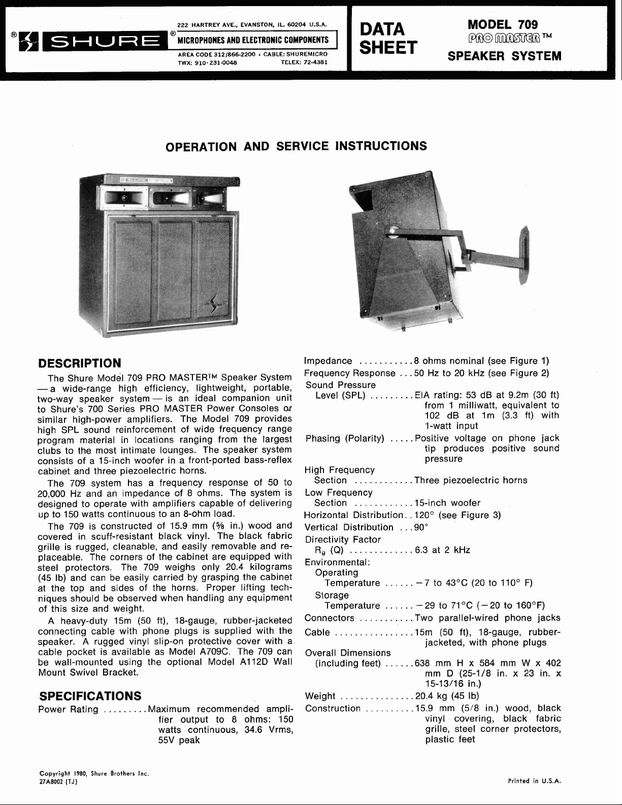
DESCRIPTION
The Shure Model 709 PRO MASTERTM Speaker System
-a wide-range high efficiency, lightweight, portable,
two-way speaker system- is an ideal companion unit
to Shure's 700 Series PRO MASTER Power Consoles
similar high-power amplifiers. The Model 709 provides
high SPL sound reinforcement of wide frequency range
program material in locations ranging from the largest
clubs to the most intimate lounges. The speaker system
consists of
cabinet and three piezoelectric horns.
The 709 system has a frequency response of 50 to
20,000 Hz and an impedance of 8 ohms. The system is
designed to operate with amplifiers capable of delivering
up to 150 watts continuous to an 8-ohm load.
The 709 is constructed of 15.9 mm
covered in scuff-resistant black vinyl. The black fabric
grille is rugged, cleanable, and easily removable and re-
placeable. The corners of the cabinet are equipped with
steel protectors. The 709 weighs only 20.4 kilograms
(45 Ib) and can be easily carried by grasping the cabinet
at the top and sides of the horns. Proper lifting tech-
niques should be observed when handling any equipment
of this size and weight.
A heavy-duty 15m (50 ft), 18-gauge, rubber-jacketed
connecting cable with phone plugs is supplied with the
speaker. A rugged vinyl slip-on protective cover with a
cable pocket is available as Model
be wall-mounted using the optional Model
Mount Swivel Bracket.
a
15-inch woofer in a front-ported bass-reflex
(5/8
in.) wood and
A709C. The 709 can
A112D Wall
or
SPECIFICATIONS
Power Rating
. . .
. . . .
.
.Maximum recommended ampli-
fier output to 8 ohms: 150
watts continuous, 34.6 Vrms,
55V peak
Impedance
Frequency Response
Sound Pressure
Level (SPL)
Phasing (Polarity)
High Frequency
Section
Low Frequency
Section
Horizontal Distribution.
Vertical Distribution
Directivity Factor
R,
Environmental:
Operating
Temperature
Storage
Temperature
Connectors
Cable
Overall Dimensions
(including feet)
Weight
Construction
. . . . . . . . . .
.
. . .
. . .
(Q)
. . . . . . . .
. . .
. . . . . . . . .
. .
. . . .
. . . . . . . .
.
.
. . . . . .
. .
. . . . . .
. . . .
.
.
.
.
. . .
. . .
. . .
.
. .
. .
. . . .
. . . . . . .
. . .
. .
. . .
.
. . .
. .
. . .
.8 ohms nominal (see Figure
.
.50 Hz to 20 kHz (see Figure
.EIA rating: 53 dB at 9.2m (30 ft)
1 milliwatt, equivalent to
from
102 dB at Im (3.3 ft) with
I-watt input
.Positive voltage on phone jack
tip produces positive sound
pressure
.Three piezoelectric horns
.15-inch woofer
.
120' (see Figure 3)
.SO0
.6.3 at 2 kHz
-
7 to 43OC (20 to 11
. .
-29 to 7I0C (-20 to 160°F)
.
.Two parallel-wired phone jacks
.
.
.
.
(50 ft), 18-gauge,
.15m
jacketed, with phone plugs
.638 mm H x 584 mm W x 402
mm D (25-1/8 in. x 23 in.
15-13/16 in.)
.20.4 kg (45 Ib)
.15.9 mm (5/8 in.) wood, black
vinyl covering, black fabric
grille, steel corner protectors,
plastic feet
O0
1)
2)
F)
rubber-
x
Copyright
27A8002
(TJ)
1980,
Shure
Brothers
Inc.
Printed
in
U.S.A.
Page 2
Optional Accessories
TYPICAL IMPEDANCE CURVE
.
.
A709C, Protective Slip-On Cover
with Cable Pocket;
Wall-Mount Swivel and Tilt
Bracket;
former
FREQUENCY IN HERTZ
FIGURE
A102A, 70-volt Trans-
1
A112D,
units). The angle of tilt (assuming a single speaker to
each side of the sound source) should be such that you
can look into the center of the speaker from the last rows
of the audience area.
If it is desirable to elevate the 709, adequate support
for heights up to about one meter (three feet) can usually
be obtained using a sturdy table or bench. The surface
must be capable of supporting the 20.4 kg (45 Ib) weight
of the speaker.
For greater elevations, the optional accessory Model
A112D Wall Mount Swivel Bracket is designed to support
the 709 for wall mounting only. It is important to note
that the 709 is not designed for mounting by simple
chains or cables to the cabinet top or sides. If the 709
must be supported by chains or cables, encircle or
cradle it.
WARNING
It is extremely important that both the mounting
surface and the mounting hardware are adequate to
support the weight of the speaker. Inadequate support may result in a hazardous operating condition.
Whatever mounting means are employed, support
should be provided for a speaker static load of
81.7 kg
20.4 kg (45 Ib).
(180 Ib). Actual weight of the speaker is
TYPICAL FREQUENCY RESPONSE
FIGURE
LEGEND LEGEND
-----
500
Hz
2
.
.
. .
. .
. . . .
. .
TYPICAL POLAR PAllERNS
FIGURE
3
INSTALLATION
General
Maximum coverage for source-oriented installations is
generally obtained with the speakers on both sides of the
sound source and as far forward as possible. Each
speaker is tilted slightly either downward (for wall- or
ceiling-mounted units) or upward (for floor-standing
HOOKUP
Amplifiers
The 709 is designed for use with the Shure 700 Series
Power Consoles and similar amplifiers having the following maximum power output capabilities.
8 ohms 4 ohms
(55V peak)
Speaker Wiring
Fifteen meters (50 ft) of cable is supplied with each
709 Speaker System. For convenient attachment, a
straight phone plug and a right-angle phone plug are
provided. Connect either end to the back of the speaker
and to the Power Consoie amplifier. The supplied cable
is 18 gauge (No. 18 AWG) and can be used for cable runs
of up to 15m (50 ft) between the speaker and the amplifier. If cable runs longer than 15m are required, use the
following table to determine the correct wire gauge.
Maximum
Distance From
Power Console
Amplifier Wire Gauge Recommended Cables
15m (50 ft) AWG 18 Belden
30m (1 00 ft) AWG 16 Belden #8470, #8471,
60m (200 ft) AWG 14 Belden
#8460, #8461,
#9470, #8542
#
8472
#8473
Page 3

Preferably, each speaker should be connected to a
separate amplifier output jack to minimize power losses
in the cable. Two parallel-wired jacks are provided on
the back of each 709 Speaker System. This allows con-
B.
Phase distortion-a type of distortion distinguish-
able by being heard only in parts of the audience
area-can be due to overlapping areas of
er coverage or sound reflecting off hard surfaces.
speak-
necting two speakers by connecting the first speaker to Re-aim the speakers to eliminate this kind of
the amplifier and the second speaker to the first.
may be helpful in certain room shapes. However, when
speakers are connected in this manner, the next heavier
wire gauge is recommended between the amplifier and
the first speaker. Therefore, for two speakers connected
together where the first is at a distance of
30m (100 ft)
from the amplifier, use No. 14 AWG cable between the
amplifier and the first speaker; for two speakers where
the first is at 15m (50 ft), use No. 16 AWG cable between
This distortion.
Use an equalization analyzer system to supply and
analyze a pink noise signal. An octave equalizer
like the ones found on the Shure 700 Series PRO
MASTERTM Power Consoles (or separate equalizers
like the Shure Models
to adjust the sound system for optimum equalization
and maximum gain before feedback.
SR107 and M610) can be used
the amplifier and the first speaker. When positioning the
speaker cables, place them where the audience, performers or passers-by will not trip over them.
To avoid frequency response aberrations, poor coverage, and dead zones caused by improper speaker phasing in multiple speaker installations, all speakers must
be wired with the same polarity. The cables listed in the
chart above are color-coded to ensure that identical connections are used. Note that even common 18-gauge
lamp cord ("zip" cord) is phase-coded with ribs along
the outer jacket of one conductor.
The cable can be stored in the convenient snap-pocket
of the optional slip-on cover for the 709 speaker.
25-Volt Line Operation
The 709 can be operated from a 25-volt line without
the need for an accessory transformer. Note that the
speaker will draw 78 watts when connected to a
constant-
voltage, 25-volt line.
SERVICE INSTRUCTIONS
Diagnosing the Problem
1. Disconnect the speaker cables.
2.
To check woofer continuity, using an ohmmeter,
measure the resistance between the tip and sleeve
of either phone jack. The dc resistance should be
5.5 to 6.5 ohms. A clicking sound will be made by a
"good" woofer when an ohmmeter is connected or
disconnected.
3. The piezoelectric horns are capacitive and cannot
be measured with an ohmmeter (the capacitive value
of each horn should be between 0.25 and 0.38
4.
For access to the piezoelectric horns, remove the
four screws holding the selected horn in the cabinet.
Carefully move the freed horn to the wider part of
pF).
the cabinet opening, and pull the horn forward and
70-Volt Line Operation
For operation from a 70-volt line, a transformer such
as the Shure Model
A102A, providing power taps of 50,
25, 12, and 6 watts, should be used.
out of the cabinet.
5. To test the individual speakers, apply a small ac
voltage from an oscillator and amplifier to each
speaker individually. Use approximately 4V, 50 Hz
to 3 kHz for the 15-inch woofer, and approximately
CHECKING SOUND COVERAGE
After the 709 speakers, Power Console amplifiers,
and other equipment have been installed and connected,
2V, 2 kHz to 8 kHz for each high-frequency horn.
As the test signal frequency is varied, any erratic
buzzes or rattles indicate possible problems.
sound coverage can be checked as follows.
1. Apply a fairly constant-level signal to the system
(preferably low-level pink noise* or program material) and walk around the audience area. Listen for
a smooth, even output from the speakers, with minimal differences in volume and tone, and no "dead"
spots or phase distortion.
A. A dead spot-for audio purposes, where no direct
sound is heard or where the sound level is ap-
preciably lower-may mean that the speakers
Sound pressure levels generated by this test may
be damaging to your hearing. Aim speakers away
from listeners and toward sound-absorbent material
(curtains, blanket, etc.) Carefully adjust test signal
amplitude to avoid unnecessarily high sound pressure levels for prolonged periods.
WARNING
are not covering that area, or that the speaker
wires are connected out-of-phase. Proper phasing can be readily determined by checking the
connections on each speaker, but inadequate
coverage generally requires repositioning the
speakers. The dead area should be examined
6. To reassemble, connect the horn leads: red lead to
the coded terminal, black lead to the other terminal.
Reinsert in the cabinet and tighten the four previously removed screws.
carefully to determine that the problem can be
corrected without resorting to auxiliary speakers.
*
Sine-wave signals delivering
because they present a much greater average power than does pink noise
or program material. Consequently, when setting up or adjusting
system with the
test signals.
709
150
watts to a speaker should be avoided
a
speaker, avoid the use of high-level, continuous-type
sound
Woofer Replacement and Jack Panel Access
1. Remove the grille by pulling the two tabs at the top.
2.
Remove the eight screws that hold the woofer in
place.
Page 4

3.
Pull the woofer forward out of the cabinet and disconnect the red and black leads from the woofer 50, 25, 12, and 6 watts for 70-volt distributed systems,
terminals. The woofer is now free from the cabinet
and can be lifted out and removed. Take care not
to damage the cone nor to break the leads when
performing this operation.
4. Before replacing the woofer, connect the leads: red
lead to the coded terminal.
5. When reassembling, insert the woofer in the cabinet
and tighten the eight previously removed screws.
6.
Press the grille back in place.
ACCESSORIES
The following optional accessories are available for
use with the 709 PRO
A709C Slip-On Protective Cover
that provides protection for the speaker. Has cutouts for
the cabinet projections used as carrying handles.
Equipped with a snap-pocket for cable storage.
A112D Wall Moun? Swivel Bracket
of the speaker about a horizontal axis, and
horizontal rotation when mounted on a vertical surface.
Heavy-duty steel construction.
MASTERTM Speaker System.
is a heavy vinyl cover
permits 90' rotation
120" of
A102A 70-Volt Transformer
and impedance taps of 8 and 16 ohms. Mounts easily to
the back of a speaker or convenient surface.
GUARANTEE
This Shure product is guaranteed in normal use to be
free from electrical and mechanical defects for a period
of one year from date of purchase. Please retain proof
of purchase date. This guarantee includes all parts and
labor. This guarantee is in lieu of any and all other guarantees or warranties, express or implied, and there shall
be no recovery for any consequential or incidental
damages.
SHIPPING INSTRUCTIONS
Carefully repack the unit and return it prepaid to:
Shure Brothers Incorporated
Attention: Service Department
1501 West Shure Drive
Arlington Heights, Illinois 60004
If outside the United States, return the unit to your
dealer or Authorized Shure Service Center for repair.
The unit will be returned to you prepaid.
provides wattage taps of
CIRCUIT DIAGRAM
REPLACEMENT PARTS LIST
Reference
Designation
J1, J2
LS1
LS2-LS4
MPI
M P2
M P3
M P4
R1
W1
*
Parts listed as RKC Kits should be ordered by that kit number. Any orders received
is shown will be shipped in RKC quantities.
4
Replacement
Kit No.*
-
RKC158
RKC165
-
-
-
-
RKC4
Qty.
1
1
-
-
-
-
1
FIGURE
Part No.
90BA2600
808363
80A372
90A2768
65A999A
53A1656B
53A1563C
45HC100D
900373
4
Replacement Kit Consists
Connector, Phone Jack, 2-Conductor,
Open Circuit
15-inch Loudspeaker
Piezoelectric Horn
Grille Assembly
Foot, Plastic
Corner Protector, Rear
Corner Protector, Front
Resistor,
Cable Assembly, 15.2m (50 ft), with
Male Phone Plugs
LSI
Of:
Description
Ion,
10W
for
piece parts where RKC Kit number
 Loading...