

Page 1
DATA SHEET No. 163A
DATE:
June 1942
SUBJECT:
MODELS 61B AND 62B VIBRATION PICKUPS
GENERAL:
brations in industrial fields. The piezoelectric element is a grafoil bimorph Rochelle salt crystal unit
with special-process moisture-proofing. The crystal
element is inertia actuated, which principle eliminates
the need of a stationary reference body in vibration
measurements. The isolated mounting used in this type
of actuation gives a maximum protection against breakage of the crystal. The assembly is enclosed in a
cast aluminum case.
The output voltage Is proportional to the vibration due to acceleration throughout the linear range
of the instruments, giving a relative measure of the
stresses set up by the vibratory motion. Model 61B
has a linear voltage-acceleration characteristic up to
approximately 1000 cycles per second, a frequency
range which is suitable for general vibration studies.
Model 62B has a voltage output about four times that
of the 61B and a linear characteristic extending to
500 cycles per second. The latter model is recommended
for applications such as the direct energizing of
headphones or oscilloscopes, which require a relatively high output voltage. Both instruments are responsive beyond the linear range, to frequencies up to
approximately 3000 cycles per second. Modification of
the frequency characteristics is possible through use
of simple circuits,
flexibility of the devices.
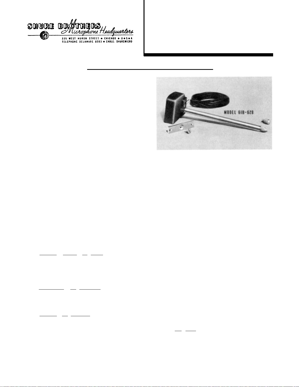
Each instrument is equipped with a complete set
of adapters Including an extension rod, ball-tip,
point-tip, and mounting bracket.
APPLICATIONS :
sign, inspection, and In many other fields. Some of
these applications are suggested below:
Industrial Research and Design: Determination of
optimum shapes and material distribution in high-speed
rotating members, motor windings, and hydraulic equipment. Research in vibration isolation materials, construction of vibration-proof rooms, vault protective
systems, etc. Noise reduction of automobile and airplane structures, gearing, bearings, etc.
Manufacturing and Inspection: Balancing of rotors, adjustment of gears and impact devices, uniformity of air-gap pull, smoothness of surfaces; vibration in machinery, building structures, transmission
lines, antenna towers, etc.
Servicing and Surveying: Location and elimina-
tion of sources of vibration, loose pistons and bear-
ings; servicing refrigerators and air-conditioning
systems; isolation of machinery, tracing leaks in
water-pipes, tanks, and hydraulic structures, geodetic
surveying for oil and mineral strata, etc.
INSTALLATION:
pickup shank. Wherever it can be used conveniently,
the screw itself will give sufficient support. Other
accessories included am a ball-tip, point-tip, and 8"
Copyright 1938, Shure Brothers, Chicago
Models 61B and 62B Vibration Pickups
are piezoelectric instruments for
the measurement and analysis of vi-
extension rod. Special. setups for production testing
may be easily constructed, but care should be taken to
resulting In a greatly increased
Models 61B and 62B Vibration Pickups
have innumerable applications in
scientific research, industrial de-
Each pickup is equipped with a sta-
tionary mounting bracket and a screw
for the 1/4" - 28 thread in the
transmit vibrations approximately along the axis of
the pickup shank.
ductor rubber-jacketed shielded cable. If necessary,
the length of cable can be increased considerably
without excessive output loss. Low-capacity high insulation-resistance shielded cable should be used.
Shielded crystal microphone cable having a capacity of
25 to 50 micromicrofarads per foot, and a leakage
resistance of 200 megohm-feet of more, is recommended. All joints should be well-shielded to avoid
hum pickup.
but the cable connector box, while reasonably moisture-
proof, will not withstand immersion in water. (For
underwater work specially constructed Instruments are
available). The pickup should not be subjected to extremely violent shocks or vibrations, nor allowed to
attain temperatures in excess of 125° F (51.7° C).
Extension rods of sufficient length will usually permit low operating temperatures near hot machinery.
CORNECTIONS:
or more. The green-coded conductor should be connected to the "high" or grid side of the amplifier
input, and the shield (black conductor) should be
connected to the ground or chassis of the amplifier:
(See Fig. 2).
high as 20 volts or more when measuring vibrations of
large amplitude. Under such circumstances, the device
should not be connected directly to the grid of the
tube without the use of a volume control or some other
type of voltage divider. A convenient way to attenuate the output voltage and avoid tube overloading is
to shunt the pickup terminals with a condenser as indicated by the dotted lines in Fig. 2. A 0.05 microfarad shunt condenser will usually reduce the peak
Fig. 1. Illustration of Models 61B and 62B
Each instrument is provided with a 7' single con-
The crystal enclosure is entirely water-tight,
The full output of the pickup may reach peaks as
Models 61B and 62B
Vibration Pickups
Vibration Pickups and accessories.
(Approximately 1/3 actual size)
The pickup should be connected to
the grid circuit of a vacuum tube
across a load resistance of ½ megohm
Page 2

No. 163
DATA SHEET
Fig. 2.
voltages to a safe value without affecting the fre-
quency characteristic. In measuring vibrations of
moderate amplitudes, this precaution may not be neces-
sary.
For most applications, a low or medium gain amplifier will be satisfactory. The pickup may be very
conveniently connected directly to conventional type
cathode-ray oscilloscopes. In cases where the output
Is sufficiently high, the vibration pickup may be used
directly with high-impedance headphones, the crystal
type being especially suitable.
The use of transformers is not generally advis-
able in conjunction with crystal devices.
OPERATION:
used for point-to-point exploration, while the round-
tip is useful in checking surfaces for smoothness.
Remote parts of machinery may be reached through use
of the extension rod.
The maximum output of the pickup is obtained when
the direction of the displacement coincides with the
axis of the pickup shank. When the extension rod is
used,
ponent of vibration along the line of action of the
rod.
In hand exploration and test set-ups, only enough
pressure should be applied to the pickup to keep it
Recommended amplifier connection for
crystal vibration pickups.
firmly In place. Excessive pressure may alter the
amplitude of vibration observed and give erroneous
readings. The instrument should never be subjected
to exceptionally violent vibrations.
suggested operating arrangements of the pickup with
head-phones, oscilloscope, wave analyzer, or amplifier
and meter.
actuated crystal are in close relationship to the
stresses set up in vibrating bodies, the amplifier
meter readings will be roughly indicative of the average vibrational stress. A calibrated cathode-ray
oscilloscope In conjunction with the pickup will serve
as a convenient means by which the values of vibra-
tional components may be estimated from visual ob-
servations.
In addition to permanent mounting
arrangements, the pickup may be held
in the hand. The point-tip may be
the readings obtained will represent the com-
temperatures exceeding 125° F. An extension rod of
sufficient length may be used to keep the pickup at a
safe distance from hot devices.
FREQUENCY
CHARACTERISTICS:
put of the 61B Pickup is very nearly proportional to
vibration acceleration up to approximately 1000 cycles
per second, and has a value of about 5 millivolts per
one-millionth inch total displacement at 250 cycles
per second. The voltage output of the 62B is approximately 20 millivolts under the same conditions, and is
essentially proportional to acceleration up to about
500 cycles per second. The total frequency range of
both pickups extends to about 3000 cycles per second.
The block schematic diagrams of Fig. 3 give some
The instruments should not be allowed to attain
Fig. 3.
Suggested indicating arrangements
for vibration pickups.
Since the forces developed in the inertia-
Frequency response curves for constant amplitude vibration are shown
in Figs. 4 and 5. The voltage out-
Fig. 4.
proximately equivalent to that of a .005 microfarad
altered, depending upon the particular conditions. As
a general rule, frequencies above 1000 cycles per
problems, the effect or the rod is usually negli-
modified, if desired, by means of simple electrocal
networks described in the Appendix, page 3. In all
Typical frequency-response characteristics
of Model 61B Vibration Pickup.
(Applies to Fig. 2 without Condenser)
up.
The internal impedance of the instrument is ap-
condenser and hence the low frequency characteristic
is dependent upon the terminal resistance employed, as
Indicated in Figs. 4 and 5. The reduction in low-
frequency response obtained by connecting the pickup
to a low terminal resistance is a decided advantage in
some cases. For general applications, a terminal re-
sistance of 1-megohm is suitable. For studying very
low frequency vibrations, a 3 to 5 megohm termination
should be used.
When the pickup is used with the extension rod,
the actual motion transmitted to the pickup may be
second will be attenuated. Since frequecies below
1000 cycles per second predominate in industrial
gible.
Frequency characteristics of the pickup may be
cases, the complete circuit, Including the network
Itself, should be fully shielded to prevent hum pick-
Page 3

No. 163
Fig. 6.
Voltage Sensitivity:
Internal Impedance:
Recommended Load
Net weight, less cable and
accessories
Net weight, with 7 ft. cable,
less accessories . . . . . . . .
Extension rod
Point-tip . . . . . . . . . . . .
Round-tip
Mounting bracket
Shipping weight
Dimensions (See Fig. 6) . . . . .
Code
. . . . . . . . . . . . . . .
Finish
List Price . . . . . . . . . . . .
Outline drawing of pickup, extension
Model 61B:
Model 62B:
Impedance
. . . . . . . . . . .
. . . . . . . . . . . .
. . . . . . . . . . . . . .
DATA SHEET
rod and tips.
SPECIFICATIONS
Approximately 5 millivolts per
one-millionth inch total displacement at 250 cycles.
Approximately 20 millivolts per
one-millionth inch total dis-
placement at 250 cycles.
Equivalent to .005 microfarad
condenser.
½ to 5 megohms. (See Figs. 4
:
and 5.)
Mode1 6lB
10½ oz.
. . . . . . . . . .
.........
.........
2½" x 2½" x 1-7/8"
Model 62B
8 oz.
1-3/8 oz.
RUTAG
Platinum Gray
$30.00 $30.00
8½ oz..
11 oz.
2½ oz.
½ oz.
½ oz.
1½ lb.
RUTAL
APPEND IX
Principles underlying measurement of vibratory motion.
The vibrations usually encountered
in industrial work are complex in
motor rotating at 1800 RPM may produce, due to small
unbalances of the rotor, a vibration of 30 cycles per
second. However, due to field unbalances, magnetic
interaction between stator and rotor fluxes, etc.,
there will be components of vibration of 60 cycles,
180 cycles, and higher frequencies. When viewed on
the screen of a cathode-ray oscilloscope, the vibration as translated by the pickup will appear as a complex pattern. By inspection, or the use of well-known
analyzing devices, this complex pattern may be re-
solved into its sinusoidal harmonic components, each
one of which may be considered by itself, insofar as
Its effects upon the vibratory system and its surround-
ings are concerned.
If a body vibrates with a simple harmonic motion,
at a frequency of f cycles per second and a maximum
displacement D, its position at any instant can be
represented by the equation:
in which d is the instantaneous displacement of the
body from the mean position at time t. The first
derivative of d with respect to t provides the expression for instantaneous velocity, while the second
derivative gives the instantaneous acceleration of the
vibratory motion. Thus,
in which v and a are instantaneous values of velocity
and acceleration respectively.
For illustrative purposes, assume a machine vibrating with a fundamental frequency of 30 cycles per
second with a .001" displacement, and a third harmonic
nature. For example, an electric
Guarantee:
of one year from date of shipment from the factory,
provided all instructions are complied with fully.
License Notice:
Each Shure Vibration Pickup is guaranteed to be free from electrical
and mechanical defects for a period
Shure Crystal Devices are licensed
under patents or the Brush Development Company. Shure patents Pending.
Fig.5. Typical frequency-response characteristic
of Model 62B showing increased sensitivity in the
lower range as compared with Model 61B.
(Applies to Fig. 2 without Condenser)
Page 4

No. 163
DATA SHEET
Linear amplitude characteristic.
Fig. 7. Oscillograms of same vibratory motion showing dependence on characteristic of the vibration pickup.
of 90 cycles per second with a .00033" displacement.
Fig. 7 shows the patterns obtained on a cathode-ray
oscilloscope for the above complex vibration when
pickups with displacement, velocity and acceleration
characteristics are used. Fig. 7-A indicates that
since the "displacement" type pickup produces a volt-
age output which is dependent upon amplitude of motion
only and independent of its frequency, the amplitudes
of the components shown in dotted lines are added to
each other, giving a picture of the instantaneous po-
sition of the vibrating body as a function of time, as
shown by the solid line. Fig. 7-B shows the pattern
resulting from a pickup generating a voltage propor-
tional to velocity of motion. Since the velocity of
motion is proportional to the product of displacement
and frequency (See Equation 2) and the third harmonic
component of the particular motion described has a
frequency three times as great and a displacement equal
to one-third that of the fundamental, both components
of the motion will have the same maximum velocity. It
should be noted that the
pattern is entirely unlike the displacement pattern.
Fig.7-C shows the components and the resultant of the
accelerations of the above motions, as given by a
pickup whose generated voltage is proportional to
acceleration of motion. Here again, there is a still
larger discrimination in favor of the higher frequency
vibrations, since the acceleration is proportional to
the product of displacement and frequency squared.
In the majority of industrial applications,
an accurate quantitative measure of the vibrations
Fig. 7-A.
resultant total velocity
Linear velocity characteristic.
Fig. 7-B. Fig. 7-C.
is usually not required. What is usually desired
is a comparison of the relative vibrations produced by
two similar devices, or the reduction in vibration
achieved through the use of different isolating ma-
terials. Since force equals the product of mass and
acceleration, acceleration is a measure of the unbalanced forces producing vibration in machinery.
Furthermore, it appears that acceleration is an approximate measure of the discomfort produced by vibratory motions (1). Therefore, when used In combination
with an amplifier and meter, the acceleration characteristic of 61B and 62B Pickups makes them suitable
for applications Involving such measurements without
the use of modifying networks. (See Figs. 4, 5 and
8-A.)
Where it is desired to determine the actual noise
resulting from a vibrating surface, the use of a
properly designed and operated sound level meter is
recommended. (See American Tentative Standards for
Sound Level Meters for Measurement of Noise and Other
Sounds, ASA Z24.3 - 1936.) Readings roughly indicative
of the relative audible noise produced by vibration of
corresponding surfaces of two similar devices can also
be obtained by the use of 61B or 62B (acceleration-
type) Vibration Pickups. For such work, the amplifier
circuit should include a weighting network represent-
ing the frequency characteristic of the human ear at a
suitable intensity level.
After an acceptable sample of a production item
has been approved through noise studies, preferably by
use of a sound level meter, the entire production may
be compared with the approved sample by means of a
vibration pickup and suitable amplifying and indicating
accessories. If a sound level meter is available for
the purpose, the vibration pickup can be substituted
for the microphone, in which case the weighting network of the sound meter can be utilized if provided in
the instrument. This method of testing may be preferable in some cases because it does not require a
sound-proof room. It should be emphasized that industrial vibration measurements require careful individual study if significant results are to be obtained.
Linear acceleration characteristic.
Fig. 8. Modifying networks and typical
corresponding frequency characteristics for
Model 61B Vibration Pickup.
Velocity of vibration can be determined by pro-
viding the network of Fig. 6-B between the pickup and
the amplifier. This characteristic may be useful In a
number of measurements required in vibration studies.
For determination of relative amplitudes of vibrations, regardless of their frequencies, the use of
an amplitude-type pickup is indicated. Such occasions
arise in rotor balancing, study of critical speeds and
other measurements in which low frequency fundamentals
play the most important part. The circuit of Fig.
8-C is intended for such purposes, providing a displacement-type characteristic for frequencies above 50
cycles per second.
(1)
F. I. Meister, "Physiological Evaluation of Shock
Measurement", Akustische Zeits 2, 1 (1937). (Reviewed in J. Acous, Soc. Am., Vol. 9, No. 1, July
1937, page 53.)
 Loading...