

Page 1
MODEL 561
OMNIDIRECTIONAL DYNAMIC MICROPHONE
The Shure Model 561 is an omnidirectional, low-impedance
dynamic microphone designed for use on a stand or flexible
gooseneck. Its smooth frequency response is tailored for optimum
speech intelligibility, making it ideal for language labs, paging
applications, and base station communications. The 561 is also
suitable for use as a talk-back or cuing microphone in TV, film, and
recording studios.
FEATURES
• Frequency response tailored for speech applications, with
bass rolloff and mid-range “presence” rise
• Omnidirectional pickup pattern
• Low impedance; long lengths of cable can be used without
affecting microphone response or level
• Shock-mounted cartridge for reduced stand and handling
noise
• Rugged die-cast aluminum construction
• Lockable stainless steel mesh grille
• Optional gooseneck and mounting flange
GOOSENECK MOUNTING AND INSTALLATION
Model 561 Dynamic Microphone
User Guide
5. Slide the cable all the way through the gooseneck.
6. Thread the microphone firmly onto the gooseneck.
7. Connect the cable wires to the amplifier, mixer, or radio
transmitter via screw terminals, an XLR connector, or a
1/4-inch phone plug. See Figure 1 and Table 1 below for wiring
information.
8. Lock the microphone in place by tightening the setscrew over
the mounting threads. The setscrew in the nameplate can be
tightened to secure the grille.
NOTE: Use Shure A95 Line Matching Transformers to match
a low impedance (300 :) microphone line to a high
impedance amplifier or mixer input. The A95 is available with
various input/output connectors.
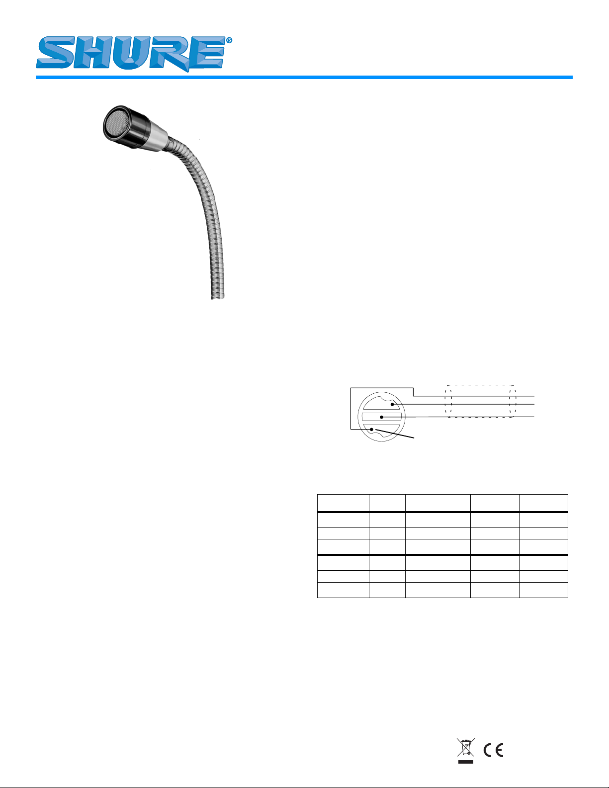
CONNECTOR WIRING
The 561 may be wired for either balanced or unbalanced
operation.
For balanced operation, the WHITE wire is connected to the
positive audio input, the BLACK wire is connected to the negative
audio input, and the SHIELD is connected to chassis ground. Refer
to Figure 1 and Table 1 below.
For unbalanced operation, the WHITE wire is connected to the
audio input, the BLACK wire is connected to audio ground, and the
SHIELD is connected to chassis ground.
CARTRIDGE CABLE
WHITE
BLACK
SHIELD
CODED TERMINAL
INTERNAL CONNECTIONS
FIGURE 1
TABLE 1. CABLE-TO-CONNECTOR WIRING
INPUT TYPE WIRE
BALANCED BLACK AUDIO - PIN 3 RING
UNBALANCED BLACK AUDIO GROUND -- SLEEVE
COLOR
WHITE AUDIO + PIN 2 TIP
SHIELD CHASSIS GROUND PIN 1 SLEEVE
WHITE AUDIO -- TIP
SHIELD CHASSIS GROUND -- SLEEVE
FUNCTION XLR
CONNECTOR
1/4 INCH
PHONE PLUG
1. If necessary, drill a hole approximately 7 mm (1/4 in.) in
diameter through the mounting surface.
2. Place the flange over the hole in the mounting surface and
secure it with three screws.
3. Thread the supplied hexnut all the way down on the flange.
4. Thread the gooseneck tightly onto the flange. Back the hexnut
up against the gooseneck. Use a wrench to tighten the nut
firmly against the bottom of the gooseneck.
©2005, Shure Incorporated
27C2057 (Rev. 7)
Printed in U.S.A.
Page 2
SPECIFICATIONS
Type
Dynamic
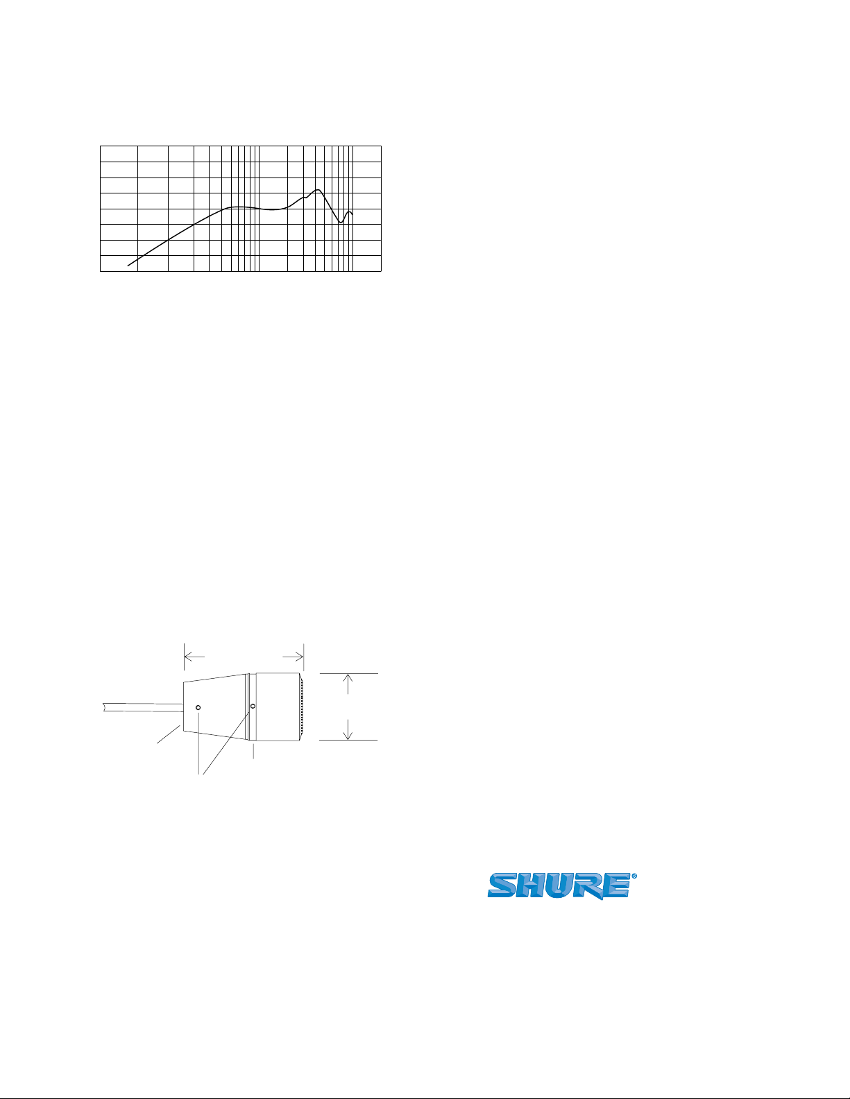
Frequency Response
40 to 10,000 Hz (See Figure 2)
+10
Bd
0
–10
Net Weight
142 grams (5 oz.)
Packaged Weight
255 grams (9 oz.)
Certification
Conforms to European Union directives, eligible to bear CE
marking; meets European Union EMC Immunity Requirements
(EN 50 082-1, 1992).
FURNISHED ACCESSORIES
Allen wrench (No. 4)......................................................... 80A67
OPTIONAL ACCESSORIES
20 200001000 1000050 100
98765432
Hz
98765432
TYPICAL FREQUENCY RESPONSE
FIGURE 2
Polar Pattern
Omnidirectional
Impedance
Rated at 150 Ohms (200 Ohms actual). Designed for
connection to inputs rated at 19 to 300 Ohms.
Output Level (at 1,000 Hz)
Open Circuit Voltage . . . . . . –57.5 dBV/Pa (1.33 mV)
(1 Pa = 94 dB SPL)
Polarity
Positive pressure on diaphragm produces positive voltage on
the white cable lead relative to the blacklead.
Cable
1.2 m (4 ft.) two-conductor, shielded, unterminated
Stand Thread
Suitable for mounting on stand or gooseneck with 5/8”–27
thread.
Case
Silver and black aluminum with stainless steel grille
Dimensions
See Figure 3
67.1 mm
(2–21/32 in.)
34.5 mm DIA.
(1–3/8 in.)
Gooseneck, 45.7 cm (18 in.) ................................................G18
Gooseneck, 45.7 cm (18 in.), Side Vent ........................... G18A
Gooseneck, 30.5 cm (12 in.) ................................................G12
Gooseneck, 15.25 cm (6 in.), Side Vent ............................. G6A
Mounting Flange................................................................... A12
Heavy-Duty Mounting Flange..........................................A13HD
REPLACEMENT PARTS
Cartridge...............................................................................R50
Screen and Grille Assembly ............................................RK85G
For additional service or parts information, please contact the
Shure Service Department at 1-800-516-2525. Outside the United
States, please contact your authorized Shure Service Center.
ARCHITECTS' SPECIFICATION
The microphone shall be a moving coil (dynamic) type with a
frequency response of 40 to 10,000 Hz. It shall have an
omnidirectional polar characteristic and a low impedance rated at
150 Ohms for connection to inputs rated 19 to 300 Ohms. The
microphone output level shall be –57.5 dBV/Pa. It shall be
equipped with a non-detachable 1.2 m (4 ft.) cable. The
microphone shall be threaded for mounting on a stand or
gooseneck with a 5/8"–27 thread. The overall dimensions of the
microphone shall be 67.1 mm (2–21/32 in.) in length and 34.5 mm
(1–3/8 in.) in diameter. The microphone shall be the Shure Model
561 or equivalent.
5/8 in.–27 thread
#4–40 Allen setscrews
Nameplate
OVERALL DIMENSIONS
FIGURE 3
SHURE Incorporated http://www.shure.com
United States, Canada, Latin America, Caribbean:
5800 W. Touhy Avenue, Niles, IL 60714-4608, U.S.A.
Phone: 847-600-2000 U.S. Fax: 847-600-1212 Intl Fax: 847-600-6446
Europe, Middle East, Africa:
Shure Europe GmbH, Phone: 49-7131-72140 Fax: 49-7131-721414
Asia, Pacific:
Shure Asia Limited, Phone: 852-2893-4290 Fax: 852-2893-4055
2
 Loading...