

Page 1
Shure
Brothers Incorporated
222 Hartrey A
Evanston IL 60202-3696 U.S.A.
venue
Phone:
In Europe, Phone: 49-7131-72140 Fax: 49-7131-721414
Internationally
800-257-4873 Fax: 847-866-2279
, Phone: 847-866-2200 Fax: 847-866-2585
W
eb Address: http://www
.shure.com
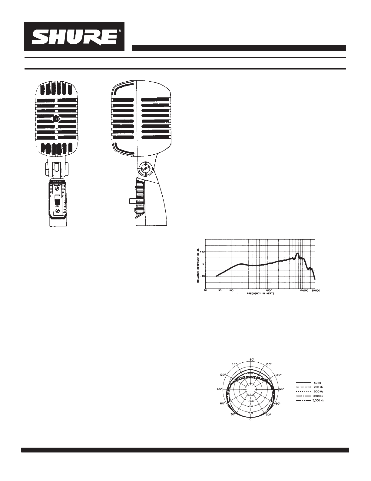
MODEL 55SH UNIDIRECTIONAL DYNAMIC MICROPHONE
Features
Classic appearance, yet modern performance
Frequency response effective for speech or vocal
and instrumental music
Cardioid directional pattern especially suited for
optimum
ments
Shock–mounted cartridge minimizes standtransmitted noise, ensures quiet operation
Rugged die cast case and mechanical design for
reliability under rigorous conditions
Self–tensioning swivel mount, permits tilting
through 45
Type
Dynamic
performance in adverse acoustic environ
forward and 80 backward
SPECIFICATIONS
Specification Sheet
-
GENERAL
The
Model 55SH Series II provides
sic UNlDYNE
II design coupled with entirely new
the Shure clas
acoustic components to meet today’s performance
standards.
This microphone is
particularly excellent for
vocal pickup with its characteristic Shure presence
peak.
The 55SH Series II has a cardioid (unidirectional)
polar
pickup pattern that minimizes sound pickup from
the
rear
of the microphone. Because of this character
the Model 55SH Series II can be used closer
istic,
usual
to loudspeakers without creating feedback prob
and will provide very satisfactory operation
lems
adverse
acoustic conditions where an omnidirectional
than
under
microphone may not function properly.
55SH Series
The
II has a low–impedance balanced
output designed for connection to microphone inputs
rated at 75 to 300 ohms. An effective new cartridge
shock mount reduces stand noise; and an On/Off
switch is supplied on the attached self–tensioning
5
swivel that mounts on a stand with a
This
microphone is ideal for
address
or theater–stage sound systems, as well as for
broadcasting,
recording, and other sound
excellent quality public
/8”–27 thread.
applications
where a stand–mounted microphone with a classic
look is desirable.
-
-
Polar Pattern
-
TYPICAL
FREQUENCY RESPONSE
FIGURE 1
Cardioid (unidirectional), uniform with frequency,
symmetrical about axis (see Figure 2)
TYPICAL POLAR P
ATTERNS
FIGURE 2
FOD NO. 01080
1997, Shure Brothers Incorporated
Page 1 of 2
Printed
in U.S.A.
Page 2
MODEL 55SH UNIDIRECTIONAL DYNAMIC MICROPHONE
Specification Sheet
Impedance
Microphone rating impedance is 150 ohms (270
ohm actual) for connection to microphone inputs
rated at 75 to 300 ohms
Output Level (at 1,000 Hz)
.
Open Circuit Voltage –78.0 dB (0.13 mV)
. . . . . .
0 dB = 1 volt per microbar
Power Level –58.5 dB.
. . . . . . . . . . . . . . . . . . . . . . . . .
0 dB = 1 milliwatt per 10 microbar
Phasing
Positive pressure on the diaphragm produces
positive voltage on pin 2 relative to pin 3 of the
output connector
Switch
Built–in On/Off switch, integral part of swivel
mount connector Three pin professional type,
designed to mate with Cannon XL series, Switchcraft A3 (Q.G.) series, or equivalent
Case
Chrome–plated die casting
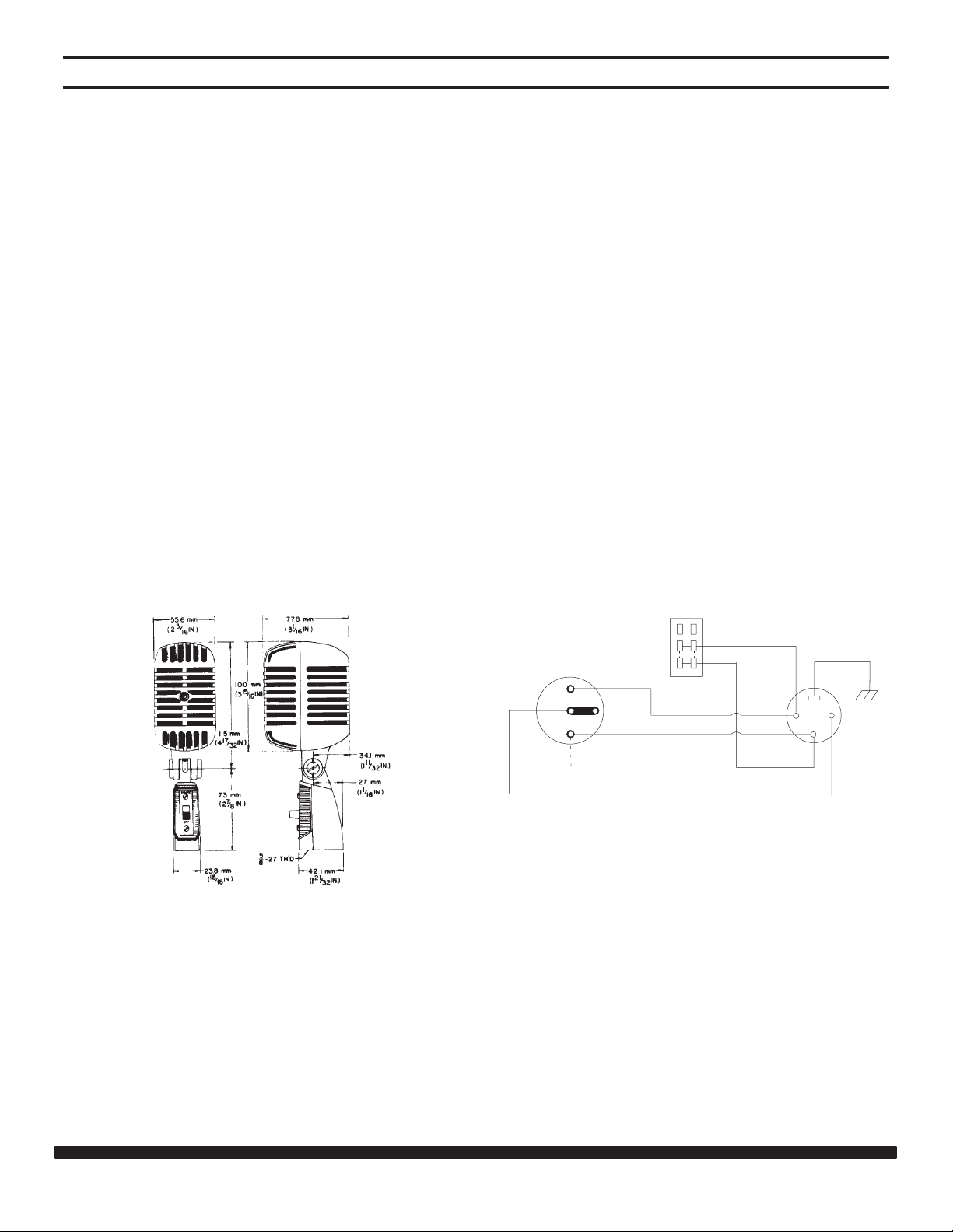
Dimensions
See Figure 3
PHASING
To test two microphones and/or their cables for
proper phasing, connect them
or
sing into them while holding them three or four
to an amplifier and talk
inch
es apart. The sound from the speakers should be the
same when talking into either microphone or directly
between
sound
talking
phones
microphones
them if they are in phase with each other
drops drastically
, or if a dead spot is found when
. If the
between the two microphones, either the micro
or their cables are out of phase. All cables and
should be tested in this
manner to ensure
-
that they are in phase with each other.
To change the phase of a low–impedance microphone cable, either use a Shure A15PRS Switchable
Phase
pins
a
Reverser or interchange the wires connected to
2 and 3 of the connector
microphone, the
microphone cartridge leads must be
. T
o change
the phase of
interchanged (see Figure 4.) This should be performed
by your dealer
, the Shure Factory Service Department,
or other qualified service personnel.
OVERALL
Net Weight
625 grams (22 oz)
Certifications
Conforms to European Union directives, eligible
to bear CE marking; meets European Union EMC
Immunity Requirements (EN 50 082–1, 1992);
RF radiated (IEC 801–3); ESD (IEC 801–2); EFT
(IEC 801–4).
DIMENSIONS
FLGURE 3
CARTRIDGE
CODED TERMINAL
INTERNAL
SWITCH
BLACK
YELLOW
BLACK
YELLOW
BLUE
CONNECTIONS
XLR CONNECTOR
1
2
3
FIGURE 4
OPTIONAL ACCESSORIES
Desk Stand
.
. . . . . . . . . . . . . . . . . . . . . . . . .
Line Matching Transformer A85F, A95UF.
Cable and Plug Assembly
.
. . . . . .
. . . . . . . . .
C25B, C25E, C25J
S37A, S39A
REPLACEMENT PARTS
Cartridge R115
On/Off
Plug Element RK169P.
.
. . . . . . . . . . . . . . . . . . . . . . . . . . . . . . .
Switch
. . . . . . . . . . . . . . . . . . . . . . . . . .
. . . . . . . . . . . . . . . . . . . . . . . . .
RK32S.
FOD
NO. 01080
1997, Shure Brothers Incorporated
Page 2 of 2
Printed
in U.S.A.
 Loading...