

Page 1
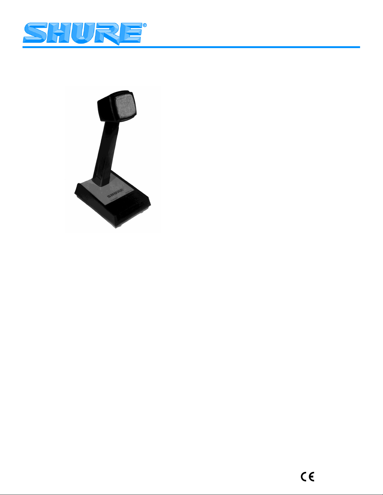
OMNIDIRECTIONAL PREAMPLIFIED DYNAMIC BASE STATION MICROPHONE
MODULINK
Note: After unpacking the microphone, remove
the protective film from the nameplate
GENERAL
The Shure 550T and 550TSB Series II Modulink Base
Station Microphones are rugged, omnidirectional dynamic microphones with a built-in preamplifier. Designed for
optimum voice clarity, they can replace dynamic or ceramic, high- or low-impedance microphones supplied as original equipment. Both models provide radio communications, paging and dispatch systems with clear, high output
voice transmission, even in noisy environments.
The 550T and 550TSB Series II are MODULINK
versal replacement microphones. They are compatible
with a variety of five-conductor, shielded, coil-cord cables
(sold separately), each of which has a locking, telephonetype modular plug on the microphone end. One cable type
has bare tinned leads on the transmitter input end so that
the user can install any desired connector. Since cable
damage is the major cause of microphone failure, this innovation allows economical, quick and simple repairs.
The 550T and 550TSB Series II microphones have extremely low sensitivity to hum pickup and low susceptibility
to rf interference. A built-in preamplifier makes them compatible with biased-audio (powered audio) radio communications systems. An externally accessible microphone
SYSTEM I
uni-
Model 550T and 550TSB Series II Modulink
Base Station Microphone User Guide
sensitivity control, located under the base, allows the operator to adjust the output level. If desired, the preamplifier
can be bypassed and the microphone can be operated in
the direct output (non-amplified) mode.
An especially useful feature for shared-channel radio
systems using the Continuous Tone Coded Squelch System (CTCSS) is the split-bar Press-to-Talk (PTT) switch.
The Transmit side of the switch can only be actuated when
the Monitor side of the switch is depressed, so the operator is forced to verify that the channel is clear before transmitting. The Monitor switch can also be locked into the “on”
position, if desired, by sliding it forward.
The 550TSB Series II microphone is functionally and
electronically identical to the 550T Series II, but it has a
single PTT switch instead of a split bar PTT switch. The
550TSB Series II can be used with trunking or other radio
systems which do not require the channel monitoring.
Both microphones are ergonomically designed; the
pushbuttons and grasping surfaces conform naturally to
the hand. The virtually indestructible ARMO-DUR
is immune to oil, grease, most fumes and solvents, salt
spray, sun, rust and corrosion. It is outstanding in its ability
to withstand mechanical shock and vibration.
The microphones’ Million-Cycle-Plusleaf switch is de-
signed for constant use even under extreme conditions.
Its nickel-silver plated blades and palladium alloy contacts resist oxidation for years.
Features
• Modular-plug coiled cord—easily changed for other
radio sets or to replace defective cable. A genuine universal replacement microphone
• Built-in preamplifier with convenient external gain ad-
justment
• Dynamic cartridge with omnidirectional pickup pattern
• Frequency response tailored for optimum speech in-
telligibility, and clear, crisp response
• Low sensitivity to rf interference and hum pickup
• Rugged, lockable PTT switch stands up under severe
environments and constant use
• High-impact ARMO-DUR case is stronger and lighter
than die-cast metal
case
2004, Shure Incorporated
27B3024 (Rev. 7)
1
Printed in U.S.A.
Page 2
MODIFICATION
The Monitor switch as provided is normally closed for radios with scanning or CTCSS functions that open when
the switch is depressed. For radios that require a normally
open (closed circuit when the microphone Monitor switch
is depressed) such as many Ericsson/GE models, perform the following modification.
1. Remove the baseplate by removing the screws secur-
ing it to the microphone.
MICROPHONE CONNECTOR WIRING
Pin
Color Function Pin Color Function
1 NC –– 5 Black PTT
Switch
Ground
2 Red Bias (+), DC
6 White Audio
Audio Out
3 Yellow PTT Switch 7 Drain Ground
4 Blue Monitor 8 NC ––
2. Locate the yellow wire from the printed circuit board to
the monitor switch.
3. Unsolder the yellow wire from the top terminal of the
monitor switch and resolder it to the lower open terminal of the monitor switch.
4. Replace the baseplate and screws.
MICROPHONE CABLES
The 550T Series II can be used with various MODULINKmicrophone cables. Each cable has a modular mi-
crophone plug on one end and the user’s choice of equipment plugs on the other. The MODULINK Cordset Table
supplied with the 550T Series II lists the most popular radios available and the cordset (ALM-) designed for use
with each. Note that the ALM-1 has no connector on the
equipment end; it can be wired as needed.
7 8
CONNECTIONS
The 550T Series II is designed to operate with two-way
radio sets with input circuits similar to those in Figure 2.
When wiring ALM-1 cables with connectors for radios not
listed in the table, modular connector pin 2 is to be used
for the dc bias resistor on the input.
1 K560
PIN 2
15 µF
PIN 7
9.6 VDC
FIGURE 2
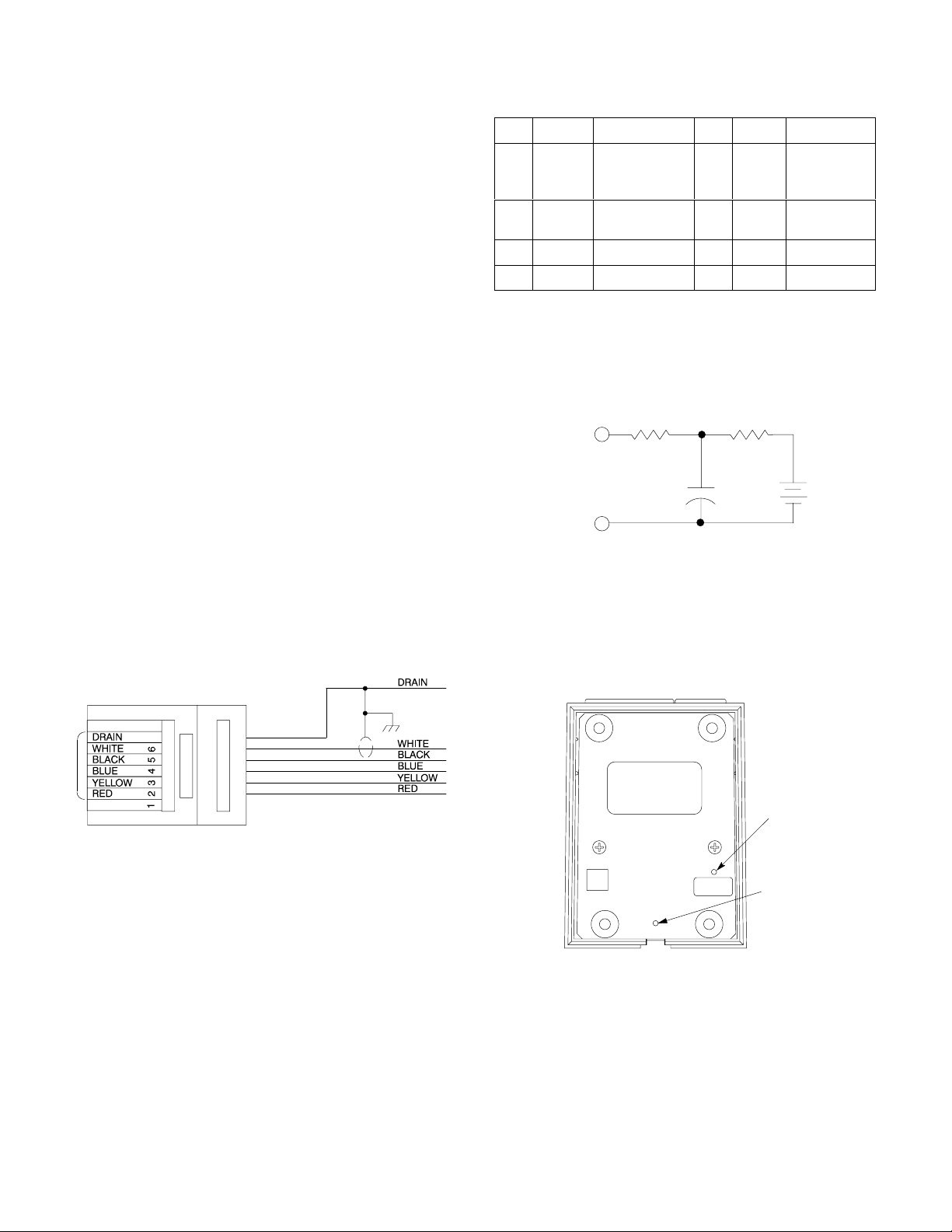
ADJUSTING OUTPUT LEVELS
To adjust the output level, proceed as follows:
1. Insert a screwdriver into the sensitivity control poten-
tiometer, located in the microphone base (see Figure 3).
2. Rotate the control counterclockwise to increase sensi-
tivity or clockwise to decrease sensitivity.
MODEL ALM-1 CABLE WIRING
FIGURE 1
The cable is attached to the 550T Series II by inserting the
modular telephone-type plug in the microphone jack until it
locks. To remove the cable from the microphone, insert the
small screwdriver supplied with the 550T Series II in bottom
case hole adjacent to the cable jack (see Figure 3) to unlock
the plug and withdraw the plug from the jack.
SENSITIVITY
ADJUST
(CCW MAX.)
MODULINK
CABLE RELEASE
FIGURE 3
INTERNAL CONNECTIONS
The circuit board layout is shown in Figure 6 and the internal electrical connections are shown in Figure 7. A schematic diagram of the circuit board is shown in Figure 8.
2
Page 3

SPECIFICATIONS
Á
Á
Á
Á
Á
Á
Á
Á
Á
Á
Á
Á
Test Conditions: (unless otherwise specified)
Audio output between pin 2 and Ground
Mic level trimmer full CCW
PTT switch depressed
Measured with High Z DMM
Standard test circuit as shown in Figure 2
Cartridge Type
Dynamic (with preamplifier)
Frequency Response
200 to 5,000 Hz (See Figure 4)
+10
0
–10
RELATIVE RESPONSE IN dB
DC Supply Current
2.5 mA ±0.25 mA
Cable (optional choice)
Detachable, 1.2 m extended (48 in.), 5-conductor (1
shielded), Neoprene-jacketed coil cord with modular
plug on microphone end (see supplied Cordset Table
for available installed equipment plugs)
CERTIFICATION
Eligible to bear CE Marking. Conforms to European EMC Directive 89/336/EEC. Meets applicable tests and performance criteria in European Standard EN55103 (1996) parts 1 and 2, for residential (E1) and light industrial (E2) environments.
Net Weight
736 grams (1 lb 10 oz)
Overall Dimensions (Figure 5)
50
100
432
FREQUENCY IN HERTZ
TYPICAL FREQUENCY RESPONSE
FIGURE 4
Polar Pattern
Omnidirectional
Sensitivity (at 1 kHz)
Cartridge Direct Output:
–35.5 dBV (16.8 mV)/100 µbar
Amplified Output:*
–4 dBV (0.63 V)/100 µbar
*Using standard test circuit shown in Figure 1, with microphone sensitivity adjustment trim potentiometer set to maximum (counterclockwise).
Hum Sensitivity
34 dB maximum equivalent SPL per 1 mOe, 60 Hz
electromagnetic field
Output Impedance
190 Ω direct output
Switches
Press-to-Talk: Double-pole, double-throw, leaf-type
switch; push-to-talk function normally open, cartridge
shunt normally closed
Monitor: Single-pole, double-throw, leaf-type switch;
normally closed
9876543298765
20000100001000
FIGURE 5
FURNISHED ACCESSORY
Hardware Kit 90SJ1371. . . . . . . . . . . . . . . . . . . . . . . . . . .
REPLACEMENT PARTS
Cartridge Assembly R147. . . . . . . . . . . . . . . . . . . . . . . . . .
For additional service or parts information, please contact Shure’s Service department at 1-800-516-2525. Outside the United States, please contact your authorized
Shure Service Center.
3
Page 4

J3 J2 J1 J4
J5
C6
C3
R5
R4
R3
C7
C8
Q1
L1
C11
C2
R2
C1
C10
R1
C9
J6
C4
J7
J8
C5
FIGURE 6
CARTRIDGE
NOTES:
1. ALL RESISTORS 1/4 W, 2%, UNLESS OTHERWISE SPECIFIED.
2. ELECTROLYTIC CAPACITORS SHOWN IN µF X VOLTS.
NON-POLARIZED CAPACITORS IN µF, 10%, 50 V OR MORE UNLESS
OTHERWISE SPECIFIED.
3. R5 GAIN ADJUSTMENT FROM BOTTOM SIDE OF BOARD.
Transmit Monitor
1
23
BLACK
WHITE
RED
ORANGE
BLACK
WHITE
GREEN
J1
J4
J3 J2
WHITE
SHIELD
J5
J6
YELLOW
FIGURE 7
BLUE
J7
J8
RED
ORANGE
4
GREEN
5
YELLOW
CCW
DC BIAS/AUDIO OUT
PTT HI
MON
PTT LO
AUDIO OUT (DIRECT)
7
GND
FIGURE 8
SHURE Incorporated Web Address: http://www.shure.com
5800 W. Touhy Avenue, Niles, IL 60714-4608, U.S.A.
Phone: 1-847-600-2000 Fax: 847-600-1212
In Europe, Phone: 49-7131-72140 Fax: 49-7131-721414
In Asia, Phone: 852-2893-4290 Fax: 852-2893-4055
Elsewhere, Fax: 847-600-6446
4
 Loading...