

Page 1
Shure Brothers Incorporated
222 Hartrey Avenue
Evanston IL 60202-3696 U.S.A.
Model 550L User Guide
•
Reliability plus—under all operating conditions
•
Neoprene feet prevent microphone slipping
PRESS-TO-TALK SWITCH OPERATION
The fingertip control bar is a non-locking switch;
simply depress the control bar and release after transmission.
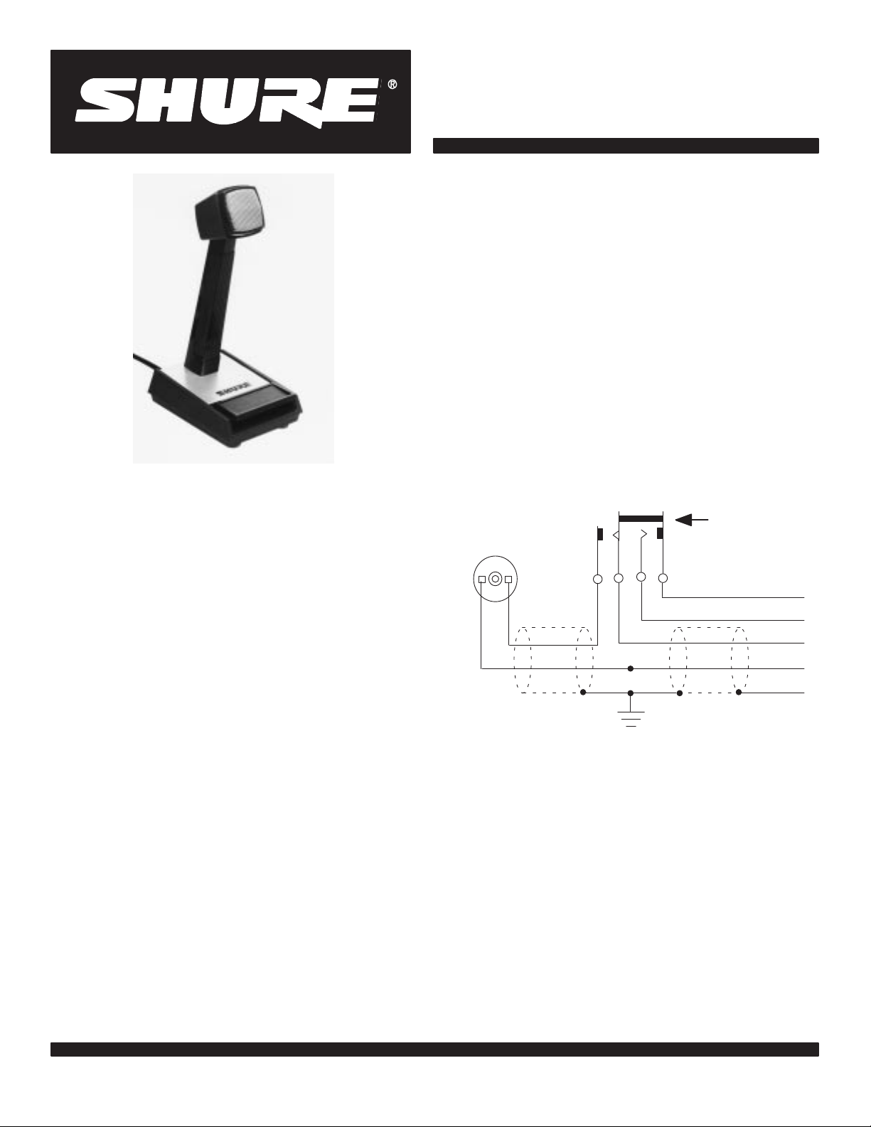
CONNECTIONS
Figure 1 shows the internal wiring of the 550L
microphone. The 550L is designed for balanced-line,
low-impedance operation. The WHITE and GREEN
cable leads are the two conductors for the microphone
circuit; the shield is connected to the amplifier or chassis ground. The RED and BLACK leads control an external relay or switching circuit.
MODEL 550L
OMNIDIRECTIONAL DYNAMIC
BASE STATION MICROPHONE
The Shure 550L is a dynamic base station microphone with a frequency response specially tailored for
voice intelligibility . It is equally useful for radio communications, paging and dispatching systems, and its
low-impedance connection makes it adaptable to most
P A amplifiers. The low-impedance design also makes
it useful for long runs, or under severe hum disturbance
conditions.
The microphone is not affected by heat or humidity .
Its exclusive ARMO-DUR
R
case is immune to oil,
grease, fumes, salt spray, sun, rust, and corrosion
—and is outstanding in its ability to resist mechanical
shocks and vibration. The “Million-Cycle” leaf-type
switch is designed to withstand rigorous operating
conditions and constant use.
Features
•
Low-impedance operation for long cable runs or
severe hum disturbance
•
Crisp, natural, high-intelligibility voice response
•
Fingertip control bar actuates microphone circuit
and external relay or control circuit
•
Long-life switch meets rigorous requirements of
communications and paging systems
•
Sturdy, high-impact ARMO-DUR base and microphone case—impervious to corrosion
TRANSMIT
RED
BLACK
RED
ORANGE
WHITE
GREEN
SHIELD
INTERNAL CONNECTIONS
FIGURE 1
Low-impedance operation is extremely useful
where long cable lengths are required, or under conditions of severe hum disturbance. The permissible
cable length is practically unlimited, since neither response nor level is appreciably affected. Shure A95
Series Line Matching Transformers are available for
use in those cases where a low-impedance microphone is to be used with an amplifier with a highimpedance input. These transformers provide a proper
impedance match between a 19- to 300-ohm microphone and a high-impedance input, and are available
with various input and output connectors.
E1998, Shure Brothers Incorporated
27A8090 (RB)
Printed in U.S.A.
Page 2
SPECIFICATIONS
Type
Dynamic
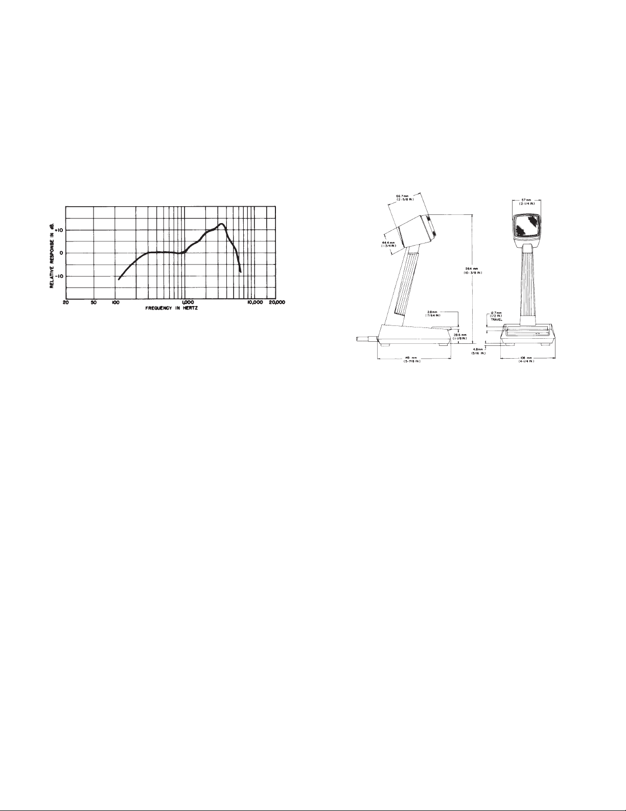
Frequency Response
150 to 6,000 Hz (see Figure 2)
Cable
2.1m (7 ft) four-conductor, two conductor
shielded, non-detachable
Case
Brown ARMO-DUR
R
with dull chrome-plated
steel screen
Dimensions
See Figure 3
TYPICAL FREQUENCY RESPONSE
FIGURE 2
Polar Pattern
Omnidirectional
Impedance (at 1,000 Hz)
Microphone rating impedance is 150 ohms (220
ohms actual) for connection to microphone inputs rated at 75 to 300 ohms
Output Level (at 1,000 Hz)
Open Circuit Voltage* –74.0 dB (0.2mV)
. . . . . . . .
Power Level** –53.5 dB. . . . . . . . . . . . . . . . . . . . . . . .
*0 dB = 1 volt per microbar
**0 dB = 1 milliwatt per 10 microbars
Switch
Press-to-Talk Switch actuates microphone circuit
and external relay or control circuit. Microphone
circuit normally open.
OVERALL DIMENSIONS
FIGURE 3
Net Weight
836 grams (1 lb 13-1/2 oz)
Shipping Weight
1.12 kilograms (2 lb 7-1/2 oz)
REPLACEMENT PARTS
Cartridge R50
. . . . . . . . . . . . . . . . . . . . . . . . . . . . . . . . . . . .
Cable C32C. . . . . . . . . . . . . . . . . . . . . . . . . . . . . . . . . . . . .
Switch RK321S. . . . . . . . . . . . . . . . . . . . . . . . . . . . . . . . . . .
For additional service or parts information, please
contact Shure’s Service Department at 1–800–
516–2525. Outside the United States, please contact
your authorized Shure Service Center.
 Loading...