

Page 1
222
HARTREY
@
AREACODE312/328-9000 .
AVE., EVANSTON. IL.
CABLE: SHUREMICRO
60204
UNIDIRECTIONAL DYNAMIC MICROPHONE
WITH BUILT-IN VIBRATION-ISOLATION SHOCK MOUNT
GENERAL
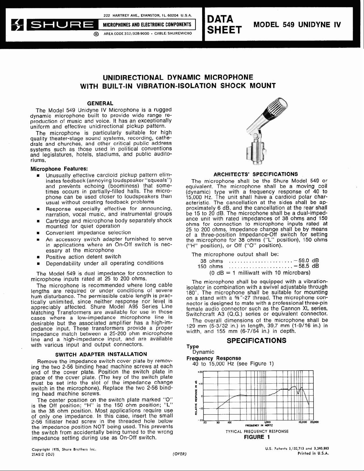
The Model 549 Unidyne IV Microphone is a rugged
dynamic microphone built to provide wide range reproduction of music and voice. It has an exceptionally
uniform and effective unidirectional pickup pattern.
The microphone is particularly suitable for high
quality theater-stage sound systems, recording, cathedrals and churches, and other critical public address
systems such as those used in political conventions
and legislatures, hotels, stadiums, and public audito-
riums.
Microphone Features:
m
Unusually effective cardioid pickup pattern eliminates feedback (annoying loudspeaker "squeals")
and
prev'ents echoing (boominess) that sometimes occurs in partially-filled halls. The microphone can be used closer to loudspeakers than
usual without creating feedback problems
Response especially effective for announcing,
narration, vocal music, and instrumental groups
Cartridge and microphone body separately shock
mounted for quiet operation
Convenient impedance selection
An accessory switch adapter furnished to serve
in applications where an On-Off switch is nec-
essary at the microphone
Positive action detent switch
Dependability under all operating conditions
The Model 549 is dual impedance for connection to
microphone inputs rated at 25 to 200 ohms.
The microphone is recommended where long cable
lengths are required or under conditions of severe
hum disturbance. The permissible cable length is prac-
tically unlimited, since neither response nor level is
appreciably affected. Shure Model A95 Series Line
Matching Transformers are available for use in those
cases where a low-impedance microphone line is
desirable but the associated amplifier has a high-impedance input. These transformers provide a proper
impedance match between a 25-200 ohm microphone
line and a high-impedance input, and are available
with various input and output connectors.
SWITCH ADAPTER INSTALLATION
Remove the impedance switch cover plate by remov-
ing the two 2-56 binding head machine screws at each
end of the cover plate. Position the switch plate in
place of the cover plate. (The key of the switch plate
must be set into the slot of the impedance change
switch in the microphone). Replace the two 2-56 binding head machine screws.
The center position on the switch plate marked
is the Off position;
"H"
is the 150 ohm position;
is the 38 ohm position. Most applications require use
of only one impedance. In this case, insert the small
2-56 fillister head screw in the threaded hole below
the impedance position NOT being used. This prevents
the switch from accidentally being turned to the wrong
impedance setting during use as On-Off switch.
"0"
"L"
U.S.A.
DATA
MODEL
549
UNIDYNE
SHEET
ARCHITECTS' SPECIFICATIONS
The microphone shall be the Shure Model 549 or
equivalent. The microphone shall be a moving coil
(dynamic) type with a frequency response of 40 to
15,000
acteristic. The cancellation at the sides shall be ap-
proximately 6 dB, and the cancellation at the rear shall
be 15 to 20 dB. The microphone shall be a dual-impedance unit with rated impedances of 38 ohms and 150
ohms for connection to microphone inputs rated at
25 to 200 ohms. Impedance change shall be by means
of a three-position Impedance-Off switch for setting
the microphone for 38 ohms
("H"
isolator in combination with a swivel adjustable through
180". The microphone shall be suitable for mounting
on a stand with a
nector is designed to mate with a professional three-pin
female audio connector such as the Cannon XL series,
Switchcraft A3
129 mm (5-3/32 in.) in length, 39.7 mm (1-9/16 in.) in
width, and 155 mm
TVD~
Frequency Response
Hz.
The unit shall have a cardioid polar char-
("L"
position), 150 ohms
position), or Off ("0" position).
The microphone output shall be:
38 ohms -59.0 dB
150 ohms
......................
......................
-
58.5 dB
(0 dB = 1 milliwatt with 10 microbars)
The microphone shall be equipped with a vibration-
5/8"-27 thread. The microphone con-
(Q.G.)
series or equivalent connector.
The overall dimensions of the microphone shall be
(6-7164 in.) in depth.
SPECIFICATIONS
.
.
Dynamic
40 to 15,000
Hz
(see Figure 1)
FREUlEffiY
TYPICAL
FREQUENCY
FIGURE
IN
MRTZ
RESPONSE
1
IV
Copyright
27A512
(OJ)
1975,
Shure
Brothers
Inc.
(OVER)
U.S.
Patents
3,132,713
Printed
and
3,240,883
in
U.S.A.
Page 2
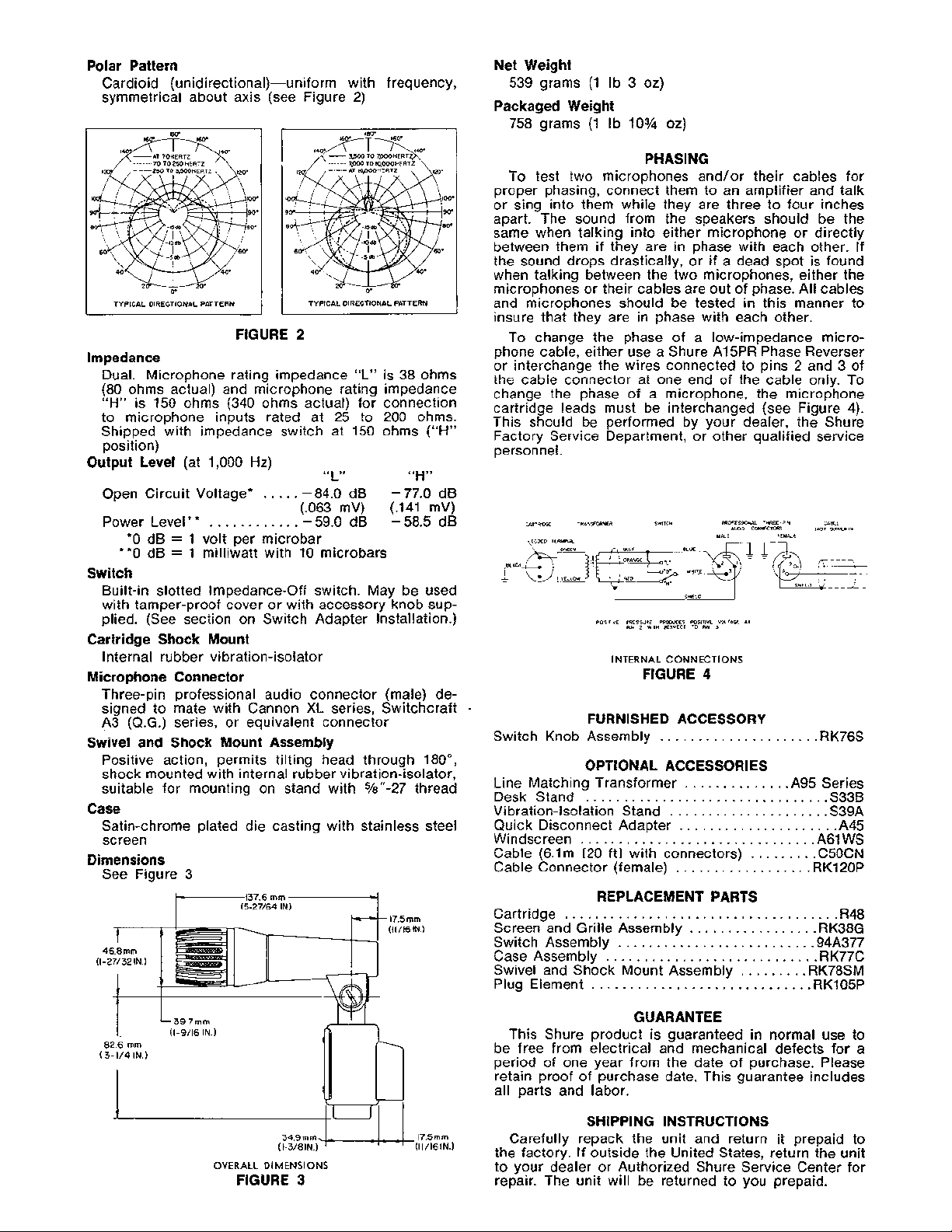
Polar Pattern
Cardioid (unidirectional)-uniform with frequency,
symmetrical about axis (see Figure 2)
TYPICAL DlRECTlONAL PATTERN
FIGURE
2
Impedance
Dual. Microphone rating impedance "L" is 38 ohms
(80 ohms actual) and microphone rating impedance
"H"
is 150 ohms (340 ohms actual) for connection
to microphone inputs rated at 25 to 200 ohms.
Shipped with impedance switch at 150 ohms
position)
Output Level
Open Circuit Voltage*
(at 1,000 Hz)
.....
"L"
-
84.0 dB -77.0 dB
"H"
(.063 mV) (.I41 mV)
PowerLevel**
dB = 1 volt per microbar
*O
............
-59.0dB -58.5dB
**0 dB = 1 milliwatt with 10 microbars
Switch
Built-in slotted Impedance-Off switch. May be used
with tamper-proof cover or with accessory knob supplied. (See section on Switch Adapter Installation.)
Cartridge Shock Mount
Internal rubber vibration-isolator
Microphone Connector
Three-pin professional audio connector (male) designed to mate with Cannon XL series, Switchcraft
A3 (Q.G.) series, or equivalent connector
Swivel and Shock Mount Assembly
Positive action, permits tilting head through 180°,
shock mounted with internal rubber vibration-isolator,
suitable for mounting on stand with
548"-27 thread
Case
Satin-chrome plated die casting with stainless steel
screen
Dimensions
See Figure 3
(ll/l6
IN.)
("H"
Net Weight
539 grams (1 Ib 3 oz)
Packaged Weight
758 grams (1 Ib 10% 02)
PHASING
To test two microphones and/or their cables for
proper phasing, connect them to an amplifier and talk
or sing into them while they are three to four inches
apart. The sound from the speakers should be the
same when talking into either microphone or directly
between them if they are in phase with each other. If
the sound drops drastically, or if a dead spot is found
when talking between the two microphones, either the
microphones or their cables are out of phase. All cables
and microphones should be tested in this manner to
insure that they are in phase with each other.
To change the phase of a low-impedance micro-
phone cable, either use a Shure
or interchange the wires connected to pins
Al5PR Phase Reverser
2
the cable connector at one end of the cable only. To
change the phase of a microphone, the microphone
cartridge leads must be interchanged (see Figure 4).
This should be performed by your dealer, the Shure
Factory Service Department, or other qualified service
personnel.
CARTRID*
-CODED
TRANSFORMER 5W1TCH PROFESSIONAL
TERMINAL
YELLOW
POSITIVE
PRESSURE PRODUCES
PIN
2
INTERNAL
POSlTiVF
Wlm
RESPECT
TO
CONNECTIONS
FIGURE
MALE
--
VOLTAGE
RN
J
FLHDLE
Al
THREE-PIN
Am0
CONNECTORS
4
.
FURNISHED ACCESSORY
Switch Knob Assembly
OPTIONAL ACCESSORIES
Line Matching Transformer
Desk Stand
................................
Vi bration-Isolation Stand
Quick Disconnect Adapter
Windscreen
...............................
Cable (6.lm [20 ftl with connectors)
Cable Connector (female)
REPLACEMENT PARTS
Cartridge
....................................
Screen and Grille Assembly
Switch Assembly
Case Assembly
............................
Swivel and Shock Mount Assembly
Plug Element
............................
....................
.............
.A95 Series
.....................
....................
........
..................
................
.........................
........
.RK78SM
and 3 of
CABLE
<No7
OUWLlEDi
.RK76S
S33B
S39A
.A45
A61 WS
.C50CN
RKIPOP
R48
.RK38G
.94A377
RK77C
.RKI05P
OVERALL
FIGURE
34.9mm,/.
(I-3/8
IN.) (ll/l6lN.)
DIMENSIONS
3
1
.I
17.5mm
GUARANTEE
This Shure product is guaranteed in normal use to
be free from electrical and mechanical defects for a
period of one year from the date of purchase. Please
retain proof of purchase date. This guarantee includes
all parts and labor.
SHIPPING INSTRUCTIONS
Carefully repack the unit and return it prepaid to
the factory. If outside the United States, return the unit
to your dealer or Authorized Shure Service Center for
repair. The unit will be returned to you prepaid.
 Loading...