

Page 1
I
222 HARTREY
D
MICROPHONES
AREA CODE 3121866-2200 - CABLE: SHUREMICRO
@
TWX: 910-231-0048 TELEX: 72-4381
AVE..
EVANSTON.
AND
ELECTRONIC
IL.
60204 U.S.A.
COMPONENTS
1
:/ET
MODELS 548,548SDY
UNIDYNEO IV
SERIES
and
5488
I
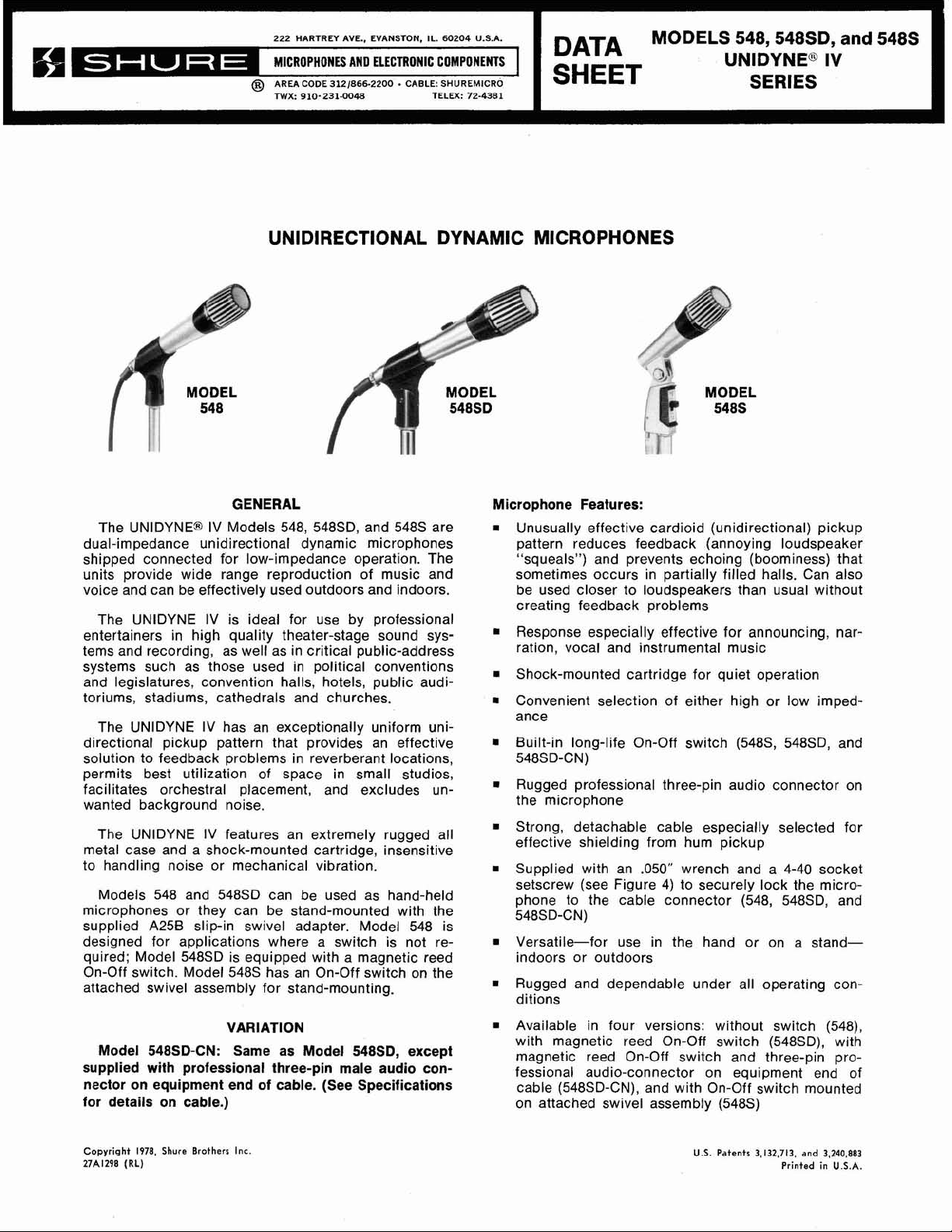
UNIDIRECTIONAL DYNAMIC MICROPHONES
GENERAL Microphone Features:
The
UNIDYNE@ IV Models 548, 548SD, and 5488 are
dual-impedance unidirectional dynamic microphones
shipped connected for low-impedance operation. The
units provide wide range reproduction of music and
voice and can be effectively used outdoors and indoors.
The UNIDYNE
entertainers in high quality theater-stage sound systems and recording, as well as in critical public-address
systems such as those used in political conventions
and legislatures, convention halls, hotels, public auditoriums, stadiums, cathedrals and churches.
The UNIDYNE
directional pickup pattern that provides an effective
solution to feedback problems in reverberant locations,
permits best utilization of space in small studios,
facilitates orchestral placement,
wanted background noise. the microphone
The UNIDYNE
metal case and a shock-mounted cartridge, insensitive
to handling noise or mechanical vibration.
Models 548 and
microphones or they can be stand-mounted with the
supplied
designed for applications where
quired; Model 548SD is equipped with a magnetic reed indoors or outdoors
On-Off switch. Model
attached swivel assembly for stand-mounting.
A25B slip-in swivel adapter. Model 548 is
IV is ideal for use by professional
IV has an exceptionally uniform uni-
and excludes un-
IV features an extremely rugged all
548SD can be used as hand-held
a
switch is not re- . Versatile-for use in the hand or on a stand-
5488 has an On-Off switch on the
Unusually effective cardioid (unidirectional) pickup
pattern reduces feedback (annoying loudspeaker
"squeals") and prevents echoing (boominess) that
sometimes occurs in partially filled halls. Can also
be used closer to loudspeakers than usual without
creating feedback problems
Response especially effective for announcing, narration, vocal and instrumental music
Shock-mounted cartridge for quiet operation
Convenient selection of either high or low imped-
ance
.
Built-in long-life On-Off switch (5488, 548SD, and
548SD-CN)
.
Rugged professional three-pin audio connector on
Strong, detachable cable especially selected for
effective shielding from hum pickup
Supplied with an
setscrew (see Figure
phone to the cable connector (548,
548SD-CN)
Rugged and dependable under all operating conditions
.050" wrench and a 4-40 socket
4)
to securely lock the micro-
548SD, and
VARIATION Available in four versions: without switch
Model 548SD-CN: Same as Model
supplied with professional three-pin male audio connector on equipment end of cable. (See Specifications
for details on cable.)
Copyright
27A1298
1978,
(RL)
Shure Brothers
Inc.
548SD, except
with magnetic reed On-Off switch (548SD), with
magnetic reed On-Off switch and three-pin
fessional audio-connector on equipment end of
(548SD-CN), and with On-Off switch mounted
cable
on attached swivel assembly
(5485)
U.S. Patents
3,132,713. and 3,240.883
(548),
pro-
Printed in U.S.A.
Page 2
SPECIFICATIONS
Type
Dynamic
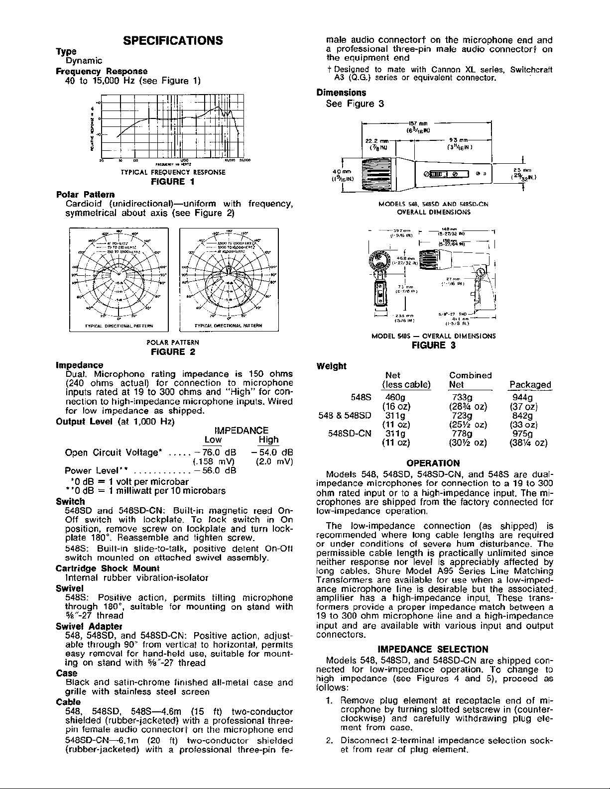
Frequency Response
40 to 15,000 Hz (see Figure 1)
male audio connector? on the microphone end and
a professional three-pin male audio
connectort on
the equipment end
t
Designed to mate with Cannon
A3
(Q.G.)
series or equivalent connector.
XL
series, Switchcraft
Dimensions
See Figure
3
TYPICAL
FREQUENCY
FIGURE
RESPONSE
1
Polar Pattern
Cardioid (unidirectional)-uniform with frequency,
symmetrical about axis (see Figure 2)
TYPICAL DIRECTIONAL PATTERN
POLAR
PATTERN
FIGURE
TYPICAL DIRECTIONAL PATTERN
2
0.
Impedance
Dual. Microphone rating impedance is 150 ohms
(240 ohms actual) for connection to microphone
inputs rated at 19 to 300 ohms and "High" for connection to high-impedance microphone inputs. Wired
for low impedance as shipped.
Output Level (at 1,000 Hz)
IMPEDANCE
Low High
Open Circuit Voltage*
. .
. . . -76.0
-
dB -54.0 dB
-
(.I58 mV) (2.0 mV)
Power Level**
.
. . . . . . . . . . .
-
56.0
dB
*O dB = 1 volt per microbar
**0 dB = 1 milliwatt per 10 microbars
Switch
548SD and 548SD-CN: Built-in magnetic reed On-
Off switch with lockplate. To lock switch in On
position, remove screw on lockplate and turn
plate 180". Reassemble and tighten screw.
5488: Built-in slide-to-talk, positive detent On-Off
switch mounted on attached swivel assembly.
Cartridge Shock Mount
Internal rubber vibration-isolator
Swivel
lock-
MODELS 548,
MODEL
Weight
Net Combined
(less cable) Net Packaged
5488 4609 7339 944g
(16 oz)
548 & 548SD 31 1 g
(1 1 02) (25% oz)
548SD-CN
31 1 g 7789 9759
(1 1 02) (30% oz) (381/! oz)
Models 548, 548SD, 548SD-CN, and 548s are dualimpedance microphones for connection to a 19 to 300
ohm rated input or to a high-impedance input. The microphones are shipped from the factory connected for
low-impedance operation.
The low-impedance connection (as shipped) is
recommended where long cable lengths are required
or under conditions of severe hum disturbance. The
permissible cable length is practically unlimited since
neither response nor level is appreciably affected by
long cables. Shure Model A95
Transformers are available for use when a
ance microphone line is desirable but the associated
548SD
OVERALL
5485
DIMENSIONS
-
OVERALL
FIGURE
OPERATION
AND
548SD-CN
DIMENSIONS
3
(28% oz)
(37 oz)
7239 8429
(33 02)
Series Line Matching
low-im~ed-
548s: Positive action, permits tilting microphone amplifier has a high-impedance input. These trans-
through
%"-27 thread
Swivel Adapter
548.
able throuih 90" from vertical to horizonta~,'~e~mits
easy removal for hand-held use, suitable for mounting on stand with %"-27 thread
Case
Black and satin-chrome finished all-metal case and
grille with stainless steel screen
Cable
548, 548SD, 548s-4.6m (15 ft) two-conductor
shielded (rubber-jacketed) with a professional
pin female audio connectort on the microphone end
548SD-CN-6.lm (20 ft) two-conductor shielded
(rubber-jacketed) with a professional three-pin
180°, suitable for mounting on stand with
formers provide a proper impedance match between a
19 to 300 ohm microphone line and a high-impedance
input and are available with various input and output
548SD. and 548SD-CN: Positive action, adiust- COnneCtors.
Models 548, 548SD, and 548SD-CN are shipped connected for low-impedance operation. To change to
high impedance (see Figures
follows:
1. Remove plug element at receptacle end of microphone by turning slotted setscrew in (counter-
three-
clockwise) and carefully withdrawing plug element from case.
2. Disconnect 2-terminal impedance selection sock-
fe-
et from rear of plug element.
IMPEDANCE SELECTION
4
and 5), proceed as
Page 3

IMPEDANCE
MODELS
SELECTION
SLOTTED SET SCREW
548.
54850
-
RECEPTACLE
FIGURE
,--PLUG ELEKNT7
4-40 SOCKET
SET SCREW
SOCKET
AND
548SD-CN
END
OF
4
MICROPHONE
MRIDGE
yEMNIL
TRANSFDRYR
WED
F
SWITCH
flyELw~l~~~
USE
WN)
MODEL
5485
-
PRXEWAL THREE-PIN
MALE
,-
j
aw
INTERNAL
FIGURE
AUIIO
WNECTORS
- -
-
- . -
cE4
l
GROW0
CONNECTIONS
7
FEWLE
CanLC
4. Re-assemble switch and nameplate to switch
housing. Tighten screws securely.
CARTRIDGE TRANSFORMR PROFESSIONAL THREE-PIN
GROUND AUDIO CONNECTORS
REED
SWITCH
POSITIVE PRESSURE PRODUCES POSITIVE VOLTAGE ON PIN
LOW IMPEDANCE; ON PIN I. HIGH IMPEDANCE.
CARTRIDGE TRPNSFORMER PROFESSIONAL THREE-PIN CAWE
GROUND
TERMINAL,
-=-
CASE GROUND
POSITIVE PRESSURE PRODUCES POSITIVE VOLTAGE
ON PIN
TERMIN,&
[CODED
2,
LOW IMPEDANCE;
MODELS
A
MODEL
INAL COOED'A'
548SD
INTERNAL
BLACK
ON
PIN I, HIGH IMPEDANCE. IMPEDANCE POSITION)
548
-
INTERNAL
FIGURE
YALE
AND
548SD-CN
CONNECTIONS
AUDIO CONNECTORS
MALE FEMALE
'-IMPEDANCE
'OCKET IN
CONNECTIONS
5
IMPEDANCE
2.
SELECTION
CABLE
POSITION1
3. Reconnect 2-terminal impedance selection socket in reverse position so that pin 3 of plug element is inserted in socket terminal
"H".
4. Reassemble plug element into microphone and
seat setscrew securely by turning out (clockwise).
5488 is shipped connected for low-impedance
Model
operation. To change to high impedance (see Figures
6 and 7), proceed as follows:
1. Remove the two No. 2-56 screws holding the
switch to connector and switch housing.
2. Remove the nameplate and take the switch out
of the switch housing.
3. Disconnect the ORANGE lead from its terminal.
Do not disconnect RED lead. Solder the ORANGE
lead to the terminal to which the WHlTE lead is
connected'
*
2-56
MACHINE
SCREWS
MICROPHONE
CASE1
NAMEPL
WHlTE
MODEL
5485 - IMPEDANCE
A-1
COVER
SELECTION
FIGURE 6
CONNECTIONS
When using the microphone in low impedance, the
BLACK and WHlTE cable leads are the "hot" conductors for balanced line connections to a low-impedance
amplifier input; the shield is connected to the chassis
or amplifier ground.
When using the microphone in high impedance, the
WHlTE cable lead is the "hot" conductor for connection to a high-impedance amplifier input; the shield
is connected to the chassis or amplifier ground. The
BLACK cable lead should be insulated at the equipment end when not used.
PHASING
To test two microphones andlor their cables for
proper phasing, connect them to an amplifier and
talk or sing into them while holding them three or
four inches apart. The sound from the speakers should
be the same when talking into either microphone or
directly between them if they are in phase with each
other. If the sound drops drastically, or if a dead spot
is found when talking between the two microphones,
either the microphones or their cables (low impedance
only) are out of phase. All cables and microphones
should be tested in this manner to insure that they
are in phase with each other.
To change the phase of a low-impedance micro-
phone cable, either use a Shure
or interchange the wires connected to pins
A15PR Phase Reverser
2
and 3
of the connector. To change the phase of a microphone, the microphone cartridge leads must be interchanged (see Figures 5 and 7). This should be performed by your dealer, the Shure Factory Service
Department, or other qualified service personnel.
FURNISHED ACCESSORIES
Swivel Adapter (548, 548SD, 548SD-CN)
......
.A25B
Connector Locking Kit (548, 548SD,
548SD-CN)
...........................
90CK1371
OPTIONAL ACCESSORIES
Line Matching Transformer
Windscreen
...............................
.............
.A95 Series
A61WS
Quick Disconnect Adapter
548SD, 548SD-CN)
(548,
(5483)
Desk Stand
....................................
....................
.........
.:.
.S37A, S39A, S40A
..
.A45, A45B
A47
REPLACEMENT PARTS
Cartridge (all models)
Cable (548,
5488, 548SD)
(548SD-CN)
Screen and Grille Assembly (all models)
Plug Element (548, 548SD, 548SD-CN)
(5488)
On-Off Switch (548SD, 548SD-CN)
(5483)
.........................
.....................
.........................
.....
......
.RK169P
C50CN
RK38G
.......................
..........
RK106S
......................
R48
.C59
RK40P
RK32S
Page 4

ARCHITECTS' SPECIFICATIONS
The microphone shall be the Shure Model 548,
548SD, 548SD-CN, 5488, or equivalent. The microphone shall be a moving coil (dynamic) type with a
frequency response of 40 to 15,000 Hz. The unit shall
have a cardioid polar characteristic. The cancellation
at the sides shall be approximately 6 dB, and the cancellation at the rear shall be 15 to 20 dB. The micro-
phone shall be dual impedance with a rated impedance
of 150 ohms for connection to microphone inputs
rated at 19 to 300 ohms and "High" for connection
to high-impedance microphone inputs. (Impedance
change shall be solderless at the microphone connector of Models 548,
The microphone output shall be:
Low lmpedance
0 dB = 1 milliwatt per 10 microbars
High lmpedance
0 dB = 1 volt per microbar
Models 548SD, 548SD-CN, and 548s shall be
equipped with a built-in On-Off switch.
Models 548,
with a swivel adapter, adjustable through
vertical to horizontal, and suitable for mounting on a
stand having a
Model
justable through
a stand having a
Models 548,
a detachable
548SD, and 548SD-CN shall be provided
%"-27 thread.
5488 shall be equipped with a swivel, ad-
548SD, and 5488 shall be provided with
4.6m (15 ft) two-conductor shielded cable
548SD, and 548SD-CN.)
................-
.
. . .
. . . . .
.
.
. .
180°, and suitable for mounting on
%"-27 thread.
.
. .
-54.0 dB
56.0 dB
90" from
with a professional three-pin audio connector* (female)
on the microphone end.
Model 548SD-CN shall be provided with a detachable
6.lm (20 ft) two-conductor shielded cable with professional three-pin audio connectors* (male and female)
on the equipment and microphone ends.
The overall dimensions of Models 548,
548SD-CN shall be 157 mm
40
mm (1-9/16 in.) in diameter.
The overall dimensions of Model
(4-23132 in.) in height, 148 mm (5-27132 in.) in
mm
depth, and 39.7 mm
*Designed to mate with Cannon
(Q.G.)
series or equivalent connector.
(1-9116 in.) in width.
(6-3116 in.) in length and
XL
series, Switchcraft
548SD, and
548s shall be 120
A3
GUARANTEE
This Shure product is guaranteed in normal use to
be free from electrical and mechanical defects for a
period of one year from date of purchase. Please
retain proof of purchase date. This guarantee includes
all parts and labor. This guarantee is in lieu of any and
all other guarantees or warranties, express or implied,
and there shall be no recovery for any consequential
or incidental damages.
SHIPPING INSTRUCTIONS
Carefully repack the unit and return it prepaid to:
Shure Brothers Incorporated
Attention: Service Department
1501 West Shure Drive
Arlington Heights, Illinois 60004
If outside the United States, return the unit to your
dealer or Authorized Shure Service Center for repair.
The unit will be returned to you prepaid.
 Loading...