

Page 1
222 HARTREY AVE., EVANSTON, IL. 60204 U.S.A.
Q
MICROPHONES AND
AREA CODE 3121866-2200 . CABLE: SHUREMICRO
TWX:
910- 231-0048 TELEX: 72-4381
ELECTRONIC
COMPONENTS
OMNIDIRECTIONAL DYNAMIC MICROPHONE
GENERAL
The Model 540SH SONODYNEQ
impedance omnidirectional dynamic microphone with
response tailoring capability at both the low and
midrange-to-high frequencies.
As supplied with its extended low and high frequency
response, the microphone is excellent for both music
and voice in public address and recording. In addition,
its tailored response provides highly intelligible speech
reproduction in communications and paging applications.
540SH microphone is designed for stand mount-
The
ing and has an On-Off switch on the integral
action swivel mount. Solderless impedance change, a
a
strong detachable cable with
audio connector, rugged construction, all make the
SONODYNE
Microphone Features:
Excellent reproduction of voice and music
Omnidirectional pickup pattern, picks up sound all
around
Response tailoring at both low and midrange-to-
high frequencies
m
Solderless impedance change
Built-in On-Off switch, an integral part of the at-
tached, positive-action swivel assembly
Rugged professional three-pin audio connector on
the microphone
Strong, detachable cable especially selected for ef-
fective shielding from hum pickup
Can be used indoors or outdoors, dependable under
all operating conditions
II
a very versatile microphone.
professional three-pin
II
is a dual-
positive-
MODEL 540SH
SONODYNE@ II
Polar Pattern
Omnidirectional
lmpedance
Dual. Microphone rating impedance is 150 ohms (230
ohms actual) for connection to microphone inputs
rated at 19 to 300 ohms and "High" for connection to
high-impedance microphone inputs. Wired for low
impedance as supplied. To change impedance, see
sections on lmpedance Selection and Connections.
Output Level
Open Circuit Voltage*. . . . . . . -79.0 dB
Power Level*
*O dB
**0 dB = 1 milliwatt per 10 microbars
(at 1,000 Hz)
*
. . . . . . . . . . . .
=
1
volt per microbar
IMPEDANCE
Low High
-55.0 dB
(.I 12 mV) (1.78 mV)
-
58.5 dB
I
SPECIFICATIONS
TY pe
Dynamic
Frequency Response
50 to 13,000
and midrange emphasis (see Figure 1)
Copyright
27A1555 (TC)
1980,
Hz.
Provision for low-frequency rolloff
TYPICAL FREQUENCY RESPONSE
FIGURE
Shure Brothers Inc.
1
Phasing
Positive pressure on diaphragm produces positive
voltage on pin
on pin
Figure
1
4.)
2
when connected for low impedance,
when connected for high impedance. (See
Switch
Built-in On-Off switch, integral part of swivel mount
Cable
4.6m (15 ft) two-conductor shielded, with professional three-pin female audio connector*
'Designed to mate with Cannon XL series, Switchcraft A3
equivalent connector
Case
Black and silver finish metal and black ARMO-DURQ
Dimensions
See Figure 2
(Q.G.)
Series, or
Printed in U.S.A.
Page 2
23.9
mm
05/16
IN)
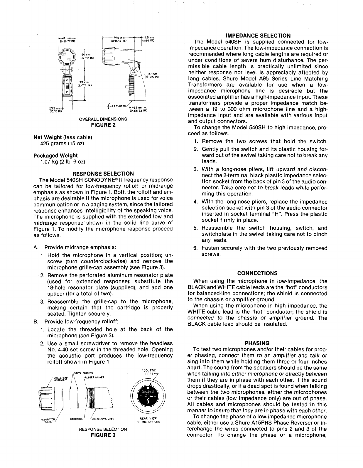
OVERALL
Net Weight (less cable)
425 grams
Packaged Weight
1.07 kg (2 I b,
The Model
can be tailored for low-frequency
emphasis as shown in Figure
phasis are desirable if the microphone is used for voice
communication or in a paging system, since the tailored
response enhances intelligibility of the speaking voice.
The microphone is supplied with the extended low and
midrange response shown in the solid line curve of
Figure
as follows.
A. Provide midrange emphasis:
1.
Hold the microphone in a vertical position; unscrew (turn counterclockwise) and remove the
microphone grille-cap assembly (see Figure 3).
2.
Remove the perforated aluminum resonator plate
(used for extended response); substitute the
18-hole resonator plate (supplied), and add one
spacer (for a total of two).
3. Reassemble the grille-cap to the microphone,
making certain that the cartridge is properly
seated. Tighten securely.
B. Provide low-frequency
1. Locate the threaded hole at the back of the
microphone (see Figure 3).
2. Use a small screwdriver to remove the headless
No. 4-40 set screw in the threaded hole. Opening
the acoustic port produces the low-frequency
rolloff shown in Figure 1.
REsoNmod GARTwDGEJ fMcRoPHoNE cnse REAR VIEW
PLATE
(1 5 oz)
6 oz)
RESPONSE SELECTION
540SH SONODYNE@ II frequency response
1. To modify the microphone response proceed
rSTEEL SPACERS
LLE-GAP
i
1)
RESPONSE
g-27THREAD"f42,1
DIMENSIONS
FIGURE 2
1. Both the rolloff and em-
rolloff:
SELECTION
FIGURE
(1-23/32 IN.)
rolloff or midrange
3
mm
4
ACOUSTIC
OF MICROPHONE
IMPEDANCE SELECTION
The Model
impedance operation. The low-impedance connection is
recommended where long cable lengths are required or
under conditions of severe hum disturbance. The permissible cable length is practically unlimited since
neither response nor level is appreciably affected by
long cables. Shure Model A95 Series Line Matching
Transformers are available for use when a
impedance microphone line is desirable but the
associated amplifier has a high-impedance input. These
transformers provide a proper impedance match between a 19 to 300 ohm microphone line and a
impedance input and are available with various input
and output connectors.
To change the Model
ceed as follows.
1. Remove the two screws that hold the switch.
2. Gently pull the switch and its plastic housing forward out of the swivel taking care not to break any
leads.
3. With
nect the 2-terminal black plastic impedance selec-
tion socket from the back of pin 3 of the audio con-
nector. Take care not to break leads while performing this operation.
4. With the long-nose pliers, replace the impedance
selection socket with pin 3 of the audio connector
inserted in socket terminal "H". Press the plastic
socket firmly in place.
5. Reassemble the switch housing, switch, and
switchplate in the swivel taking care not to pinch
any leads.
6.
Fasten securely with the two previously removed
screws.
When using the microphone in low-impedance, the
BLACK and WHITE cable leads are the "hot" conductors
for balanced-line connections; the shield is connected
to the chassis or amplifier ground.
When using the microphone in high impedance, the
WHITE cable lead is the "hot" conductor; the shield is
connected to the chassis or amplifier ground. The
BLACK cable lead should be insulated.
To test two microphones
er phasing, connect them to an amplifier and talk or
sing into them while holding them three or four inches
apart. The sound from the speakers should be the same
when talking into either microphone or directly between
them if they are in phase with each other. If the sound
drops drastically, or if a dead spot is found when talking
between the two microphones, either the microphones
or their cables (low impedance only) are out of phase.
All cables and microphones should be tested in this
manner to insure that they are in phase with each other.
To change the phase of a low-impedance microphone
cable, either use a Shure
terchange the wires connected to pins
connector. To change the phase of a microphone,
540SH is supplied connected for low-
540SH to high impedance, pro-
a
long-nose pliers, lift upward and discon-
CONNECTIONS
PHASING
andlor their cables for prop-
A15PRS Phase Reverser or in-
2
and 3 of the
low-
high-
Page 3

the microphone cartridge leads must be interchanged
(see Figure 4). This should be performed by your dealer,
the Shure Factory Service Department, or other
qualified service personnel.
CARTRIDGE TRANSFORMER SWITCH THREE-PIN PROFESSIONAL CABLE
COOED MALE FEMALE
TERMINAL
INTERNAL
CONNECTIONS
FIGURE
AUDIO CONNECTORS
4
FURNISHED ACCESSORIES
Resonator Plate
Spacer
....................................
Lockplate
............................
53A629A
................................
90NR1371
.53A487
OPTIONAL ACCESSORIES
Line Matching Transformer
Desk Stand
........
S33B, S37A. S38B, S39A, or S40A
Quick Disconnect Adapter
...............
A95 Series
......................
A47
REPLACEMENT PARTS
Cartridge
Cable
......................................
..........................................
R50
C59
ARCHITECTS' SPECIFICATIONS
The microphone shall be a moving coil (dynamic) type
with a frequency response of 50 to 13,000 Hz. The
microphone shall have provision for adjusting the low
frequencies and the middle-to-high frequencies. The
unit shall have an omnidirectional polar characteristic.
The microphone shall be a dual-impedance unit with a
rated impedance of 150 ohms for connection to
microphone inputs rated at 19 to 300 ohms and "High"
for connection to high-impedance microphone inputs.
lmpedance change shall be solderless at the
microphone connector.
The microphone output shall be:
Low Impedance
.....................
-58.5 dB
(0 dB = 1 milliwatt per 10 microbars)
High impedance
(0 dB
.....................
=
I
volt per microbar)
The microphone shall be equipped with a built-in
-55.0 dB
On-
Off switch and an integral swivel assembly suitable for
mounting on a stand with a 518"-27 thread. The
microphone shall be provided with a detachable
4.6m
(15 ft) two-conductor shielded cable with a professional
three-pin female audio connector* at the microphone
end. The overall dimensions of the microphone shall be
123 mm (4-27132 in.) in height, 42.1 mm (1-21132 in.) in
width, and 92.1 mm (3-518 in.) in depth.
The microphone shall be the Shure Model
540SH or
equivalent.
*Designed to mate with Cannon
eauivalent connector.
XL
series, Switchcraft
A3
(Q.G.)
series, or
GUARANTEE
This Shure product is guaranteed in normal use to be
free from electrical and mechanical defects for a period
of one year from date of purchase. Please retain proof
of purchase date. This guarantee includes all parts and
labor. This guarantee is in lieu of any and all other
guarantees or warranties, express or implied, and there
shall be no recovery for any consequential or incidental
damages.
SHIPPING INSTRUCTIONS
Carefully repack the unit and return it prepaid to:
Shure Brothers Incorporated
Attention: Service Department
1501 West Shure Drive
Arlington Heights, Illinois 60004
If outside the United States, return the unit to your
dealer or Authorized Shure Service Center for repair.
The unit will be returned to you prepaid.
 Loading...