

222 HARTREY AVL, EVANSTON. I
a
AREA
CODEJI~/~~~-~OOO
L.
60204 U.S A.
.
CABLE. SHUREMICRO
BASE STATION CITIZENS BAND POWER MICROPHONE
GENERAL
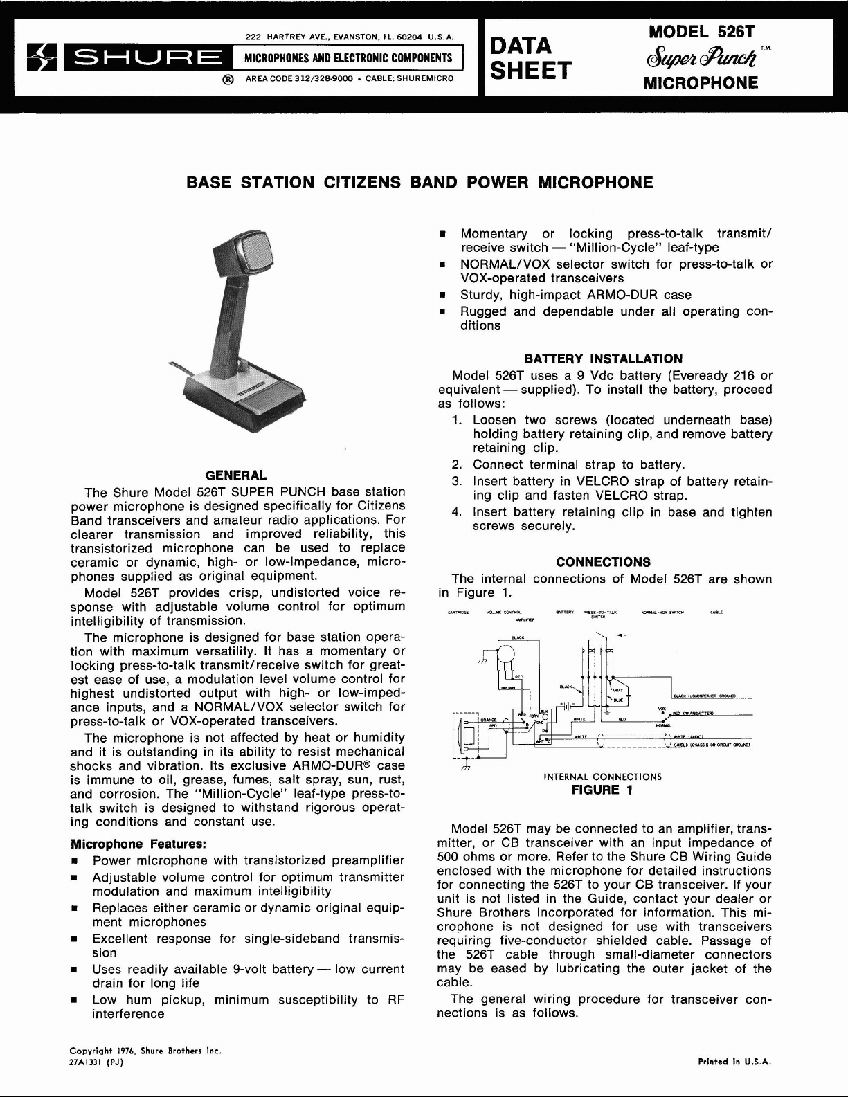
The Shure Model 526T SUPER PUNCH base station
power microphone is designed specifically for Citizens
Band transceivers and amateur radio applications. For
clearer transmission and improved reliability, this
transistorized microphone can be used to replace
ceramic or dynamic, high- or low-impedance, micro-
phones supplied as original equipment.
Model 526T provides crisp, undistorted voice re-
sponse with adjustable volume control for optimum
intelligibility of transmission.
The microphone is designed for base station opera-
tion with maximum versatility. It has a momentary or
locking press-to-talk
est ease of use, a modulation level volume control for
highest undistorted output with high- or
ance inputs, and a NORMALIVOX selector switch for
press-to-talk or VOX-operated transceivers.
The microphone is not affected by heat or humidity
and it is outstanding in its ability to resist mechanical
shocks and vibration. Its exclusive
is immune to oil, grease, fumes, salt spray, sun, rust,
and corrosion. The "Million-Cycle" leaf-type press-totalk switch is designed to withstand rigorous operating conditions and constant use.
Microphone Features:
Power microphone with transistorized preamplifier
Adjustable volume control for optimum transmitter
modulation and maximum intelligibility
Replaces either ceramic or dynamic original equip-
ment microphones
Excellent response for single-sideband transmis-
sion
Uses readily available 9-volt battery - low current
drain for long life
Low hum pickup, minimum susceptibility to RF
interference
transmitlreceive switch for great-
low-imped-
ARMO-DUR@ case
MODEL 526T
DATA
SHEET
m
Momentary or locking press-to-talk transmit1
receive switch - "Million-Cycle" leaf-type
NORMALIVOX selector switch for press-to-talk or
VOX-operated transceivers
Sturdy, high-impact ARMO-DUR case
Rugged and dependable under all operating con-
ditions
BATTERY INSTALLATION
Model 526T uses a 9 Vdc battery (Eveready 216 or
-
equivalent
as follows:
1. Loosen two screws (located underneath base)
holding battery retaining clip, and remove battery
retaining clip.
2. Connect terminal strap to battery.
3.
Insert battery in VELCRO strap of battery retaining clip and fasten VELCRO strap.
4.
Insert battery retaining clip in base and tighten
screws securely.
The internal connections of Model 526T are shown
in Figure
Model 526T may be connected to an amplifier, trans-
mitter, or CB transceiver with an input impedance of
500
ohms or more. Refer to the Shure CB Wiring Guide
enclosed with the microphone for detailed instructions
for connecting the 526T to your CB transceiver. If your
unit is not listed in the Guide, contact your dealer or
Shure Brothers Incorporated for information. This microphone is not designed for use with transceivers
requiring five-conductor shielded cable. Passage of
the 526T cable through small-diameter connectors
may be eased by lubricating the outer jacket of the
cable.
The general wiring procedure for transceiver con-
nections is as follows.
supplied). To install the battery, proceed
CONNECTIONS
1.
INTERNAL
CONNECTIONS
FIGURE
MICROPHONE
1
Copyright
27A1331
1976,
(PJ)
Shure
Brothers
Inc.
Printed in
U.S.A.
Relay or Switching Circuit:
GROUNDED SWITCHING
Most transceivers employ a grounded circuit to
switch from the receive to the transmit position. To
connect the microphone to such a circuit, proceed
as follows.
1. Unscrew the two screws securing the microphone baseplate, and remove the baseplate.
2. Cut the GRAY lead connecting two terminals of
the press-to-talk switch (see Figure 1).
3.
Reassemble the baseplate to the microphone and
fasten securely with the previously removed
screws.
4.
At the end of the cable, connect the RED lead
to the terminal used to complete the transmitter
circuit.
5. Connect the BLACK lead to the terminal used to
complete the receiver circuit. This will usually
be a ground return from the loudspeaker. If a microphone switching contact is not required for
the loudspeaker ground, insulate (wrap with
tape) the BLACK cable lead.
6. Connect the shield to chassis or circuit ground
of the transceiver (see Guide).
Microphone Audio Input Circuit:
Connect the WHITE cable lead to the microphone
audio input terminal.
VOLUME CONTROL
When the 526T replaces a ceramic (usually
highimpedance) microphone supplied as original equipment, the volume control should be set at the lower
ranges to prevent overmodulation and unintelligible
transmission. Correct modulation can be checked on
the modulation level indicator.
When the 526T replaces a dynamic (usually
lowimpedance) microphone supplied as original equipment, the volume control should be set at the upper
ranges for correct modulation as indicated on the
modulation level indicator.
VOX OPERATION
Most amateur equipment and some CB transceivers
are designed for either press-to-talk or VOX
(voiceoperated relay) operation. The Model 526T provides
for operation in either mode by use of the NORMAL/
VOX slide switch on the bottom of the microphone
base.
For press-to-talk operation, the slide switch should
be in the NORMAL position. For VOX operation, the
switch should be in the VOX position with the control
bar locked in the On position.
ISOLATED SWITCHING
In some transceivers, an isolated circuit is required
to switch power supply voltages rather than grounds.
If an isolated switching circuit is required, proceed
as follows.
1. Unscrew the two screws securing the microphone baseplate, and remove the baseplate.
2. Clip and insulate the BLUE lead from the
press-
to-talk switch to the ground lug (see Figure 1).
3.
Reassemble the baseplate to the microphone
and fasten securely with the previously removed
screws.
4.
At the end of the cable, connect the RED lead to
the isolated switch contact terminal used to
complete the transmitter circuit.
5. Connect the BLACK lead to the other isolated
switch contact terminal used for power supply
voltage.
6. Connect the shield to chassis or circuit ground
of the transceiver (see Guide).
CAUTION
Make certain that the shield is not connected to
chassis ground for those models where the Guide specifies the shield should be connected to circuit ground.
NOTE
In some transceivers, there may be oscillation,
squealing, or low volume in the Receive mode. In any
of these cases, clip and insulate the WHITE lead
between the printed circuit assembly and the normally
closed contact of the press-to-talk switch (see Fig-
1).
ure
LOCKING PRESS-TO-TALK SWITCH
The fingertip control bar of the press-to-talk switch
can be used in a momentary or locked-on position. For
use as a momentary switch, depress the control bar
and release after transmission. To lock the switch in
the On position, depress the control bar and move it
forward with the fingertips. To unlock the switch, move
the control bar backward and remove pressure.
SPECIFICATIONS
TY pe
Dynamic (with transistor preamplifier)
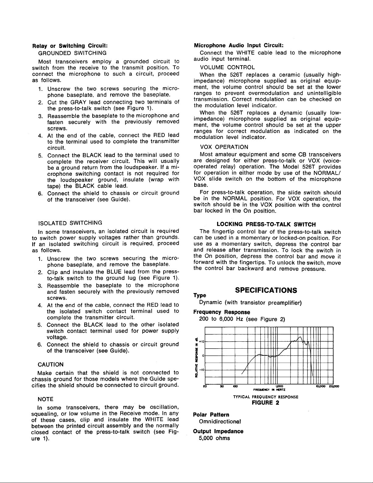
Frequency Response
Hz
200 to 6,000
TYPICAL
Polar Pattern
Omnidirectional
Output Impedance
5,000
ohms
(see Figure
FREQUENCY
FIGURE
2)
RESPONSE
2

Load Impedance
500 ohms minimum
Net Weight
920 grams (2 Ib)
Output Level
Adjustable from 0.63 to 14
Signal Handling Capability
111 dB SPL at 1,000 Hz produces 1.OV with volume
control at maximum
Battery Type
9 Vdc (Eveready 216 or equivalent)
Battery Drain
0.9 mA
Battery Life
300 hours minimum, 1 year maximum
Switches
Press-to-talk: single-bar, momentary or locking, leaf-
type switch
NORMAL/VOX: single-pole double-throw slide
switch
Cable
2.lm (7 ft) three-conductor shielded, plastic jacketed, attached cable
Case
Black, high-impact ARMO-DUR@
Dimensions
See Figure
(at 1,000 Hz with 100 kilohm load)
mV for 1 microbar input
(with 50 kilohm load)
3
Packaged Weight
1.2 kilograms (2 Ib, 11 oz)
REPLACEMENT PARTS
Cartridge R96
Grille Assembly .90D1844
Battery Retaining Clip .90A2351
Baseplate with NORMAL/VOX Switch
Cable
Switch Blade Assembly .90A2595
Volume Control .46A060
Printed Circuit Assembly .90A2617
Shure Brothers Incorporated ("Shure"), 222 Hartrey
Avenue, Evanston, Illinois 60204, warrants to the owner
of this product that it will be free, in normal use, of
any
of one year from date of purchase. You should retain
proof of date of purchase. Shure is not liable for any
consequential damages. If this Shure product has any
defects as described above, carefully repack the unit
and return it prepaid to the above address. If you are
not in the United States, return the unit to your dealer
or authorized Service Center for repair. The unit will
be repaired or replaced and returned to you promptly,
and if it cannot be repaired or replaced, you may elect
to receive
....................................
.........................
....................
......
.90A2348
...................................
..................
..........................
.................
FULL ONE YEAR WARRANTY
defects in workmanship and materials for a period
a
refund.
7
0A3092
OVERALL DIMENSIONS
FIGURE
3

 Loading...