

Page 1

Model 526T Series II Super Punch
Microphone User Guide
TRANSISTORIZED BASE STATION MICROPHONE
S Replaces either ceramic or dynamic original equip-
ment microphones
S Excellent response for single-sideband transmission
S Uses readily available 9-volt battery—low current
drain for long life
S Low hum pickup, minimum susceptibility to RF inter-
ference
S Momentary or locking press-to-talk transmit/receive
switch –”Million Cycle” leaf-type
S Universal six-wire cable for instant microphone-trans-
ceiver connection
S Sturdy, high-impact ARMO-DUR
S Rugged and dependable under all operating
conditions
case
GENERAL
The Shure Model 526T Series II SUPER PUNCH
station microphone is designed for clearer transmission and
improved reliability. This transistorized microphone can be
used to replace ceramic or dynamic, high- or low-impedance
microphones supplied as original equipment.
Model 526T Series II provides crisp, undistorted voice response with adjustable volume control for optimum intelligibility of transmission.
The microphone is designed for maximum versatility in
base station operation. It has a momentary or locking pressto-talk transmit/receive switch for greatest ease of use, and
a modulation level volume control for highest undistorted
output with high- or low-impedance inputs. The supplied sixwire cable and triple-pole double-throw switch are arranged
for universal microphone-transceiver connection.
The microphone is not affected by heat or humidity, and it
is oustanding in its ability to resist mechanical shocks and
vibration. Its exclusive ARMO-DUR
grease, fumes, salt spray, sun, rust, and corrosion. The “Million Cycle” leaf-type press-to-talk switch is designed to withstand rigorous operating conditions and constant use.
Microphone Features:
case is immune to oil,
base
S Dynamic microphone with transistorized preamplifier
S Adjustable volume control for optimum transmiter
modulation and maximum intelligibility
BATTERY INSTALLATION
Model 526T Series II uses a 9 Vdc battery (90AJ1371).To
install the battery, proceed as follows:
1. Loosen two screws (located underneath base) holding
battery retaining clip, and remove battery retaining
clip.
2. Connect terminal strap to battery.
3. Insert battery in VELCRO strap of battery retaining
cllip and fasten VELCRO strap.
4. Insert battery retaining clip in base and tighten screws
securely.
CONNECTIONS
Model 527T Series II can be connected to an input (transceiver, transmitter, or amplifier) of 500 ohms or more. For detailed instructions for connecting the 526T Series II to CB or
ham transceivers. If your unit is not listed in the Guide, contact your dealer or Shure Incorporated for information.
A piece of tubing is attached to the plug end of the cable
for use as a strain relief for plugs with large cable entry holes.
Remove the tubing when not required.
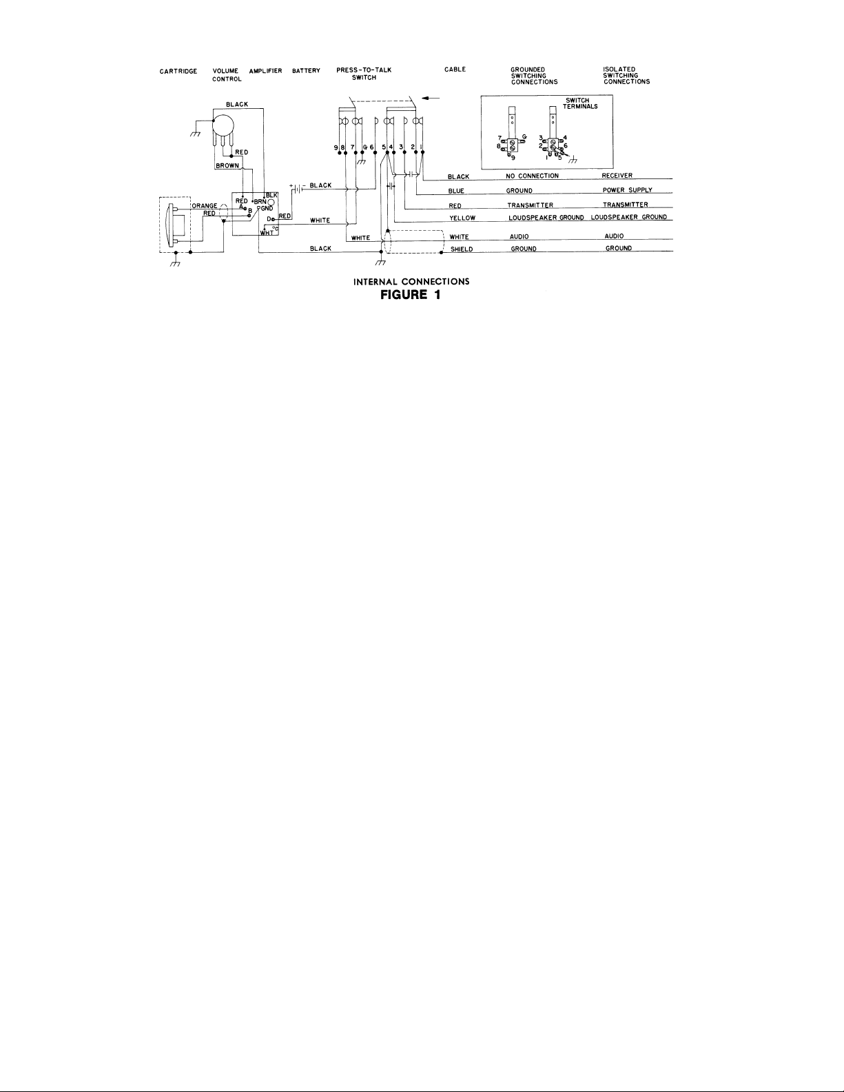
The internal connections of Model 526T Series II are as
shown in Figure 1.
2001, Shure Incorporated
27B1468 (AI)
Printed in Mexico
Page 2
9Vdc
The general wiring procedure for tranceiver connections
is as follows:
Microphone Audio Input Circuit:
1. Connect the WHITE cable lead to the microphone audio input terminal.
2. Connect the SHIELD to chassis or circuit ground of
the transceiver (see Guide and CAUTION
below).
Electronic or Relay Switching Circuit:
GROUNDED SWITCHING
Most transceivers employ a grounded circuit to switch
from the receive to the transmit position. To connect the microphone to such a circuit, proceed as follows:
1. At the end of the cable, connect the RED lead to the
terminal used to complete the transmitter circuit.
2. Connect the BLUE lead to chassis or circuit ground of
the transceiver (see Guide and CAUTION below).
3. Connect the YELLOW lead to the terminal used to
complete the receiver circuit. This will usually be a
ground return from the loudspeaker circuit. If a microphone switching contact is not required for loudspeaker ground, insulate (wrap with tape) the YELLOW
lead.
4. The BLACK lead is usually not used; insulate the
BLACK lead. However, if both a receiver ground and a
loudspeaker ground are required, connect the YELLOW lead to loudspeaker ground, and the BLACK
lead to the receiver ground.
ISOLATED SWITCHING
In some transceivers, an isolated circuit is required to
switch power supply voltages rather than grounds. If an isolated switching circuit is required, proceed as follows:
1. At the end of the cable, connect the RED lead to the
isolated switch contact terminal used to complete the
transmitter circuit.
2. Connect the BLUE lead to the terminal used for the
switched power supply.
3. Connect the BLACK lead to the terminal used to complete the receiver circuit. If the power supply is not
switched to the receiver circuit by a microphone
switching contact, insulate (wrap with tape) the
BLACK lead.
4. Connect the YELLOW lead to the loudspeaker ground
return. If a microphone switching contact is not required for the loudspeaker ground, insulate the YELLOW cable lead.
CAUTION
Make certain that the SHIELD and/or the BLUE lead are
not connected to chassis ground for those models where the
Guide specifies they should be connected to circuit ground.
SPECIAL SWITCHING
In some transceivers, special switching circuits are required. Three types are described below. In all of the types,
before making the required circuit alterations, remove the
microphone baseplate by unscrewing the two screws securing it.
1. If a grounded audio input is required in the receive
mode, solder a jumper lead between switch terminal 9
and the ground lug (see Figure 1).
2. If both and isolated and grounded transmit circuit are
required, along with a grounded receive circuit (see
Figure 1):
a) Unsolder the WHITE leads from switch terminals 7
and 8.
b) Solder the WHITE leads together, and insulate the
connection.
c) Cut the BLACK cable lead from terminal 1 and sol-
der it to terminal 8.
d) Solder a jumper lead between terminal 7 and the
ground lug.
At the end of the cable, the BLUE and RED leads are now
the isolated transmit leads; the BLACK lead is the grounded
transmit lead; and the YELLOW lead is the grounded receive
lead.
3. If both an isolated and grounded receive circuit are
required, along with a grounded transmit circuit (see
Figure 1):
2
Page 3

a) Unsolder the WHITE leads from switch terminals 7
and 8.
b) Solder the WHITE leads together, and insulate the
connection.
c) Unsolder the RED cable lead from terminal 3 and
solder it to terminal 8.
d) Solder a jumper lead between terminal 7 and the
ground lug.
At the end of the cable, BLACK and BLUE leads are now
the isolated receive leads; the YELLOW lead is the
grounded receive lead; and the RED lead is the grounded
transmit lead.
VOLUME CONTROL
When the 526T Series II replaces a dynamic (usually low–
impedance) microphone supplied as original equipment, the
volume control should be set at the lower ranges to prevent
overmodulation and unintelligible transmission. Correct
modulation can be checked on the modulation level indicator.
When the 526T Series II replaces a ceramic (usually highimpedance) microphone supplied as original equipment, the
volume control should be set at the upper ranges for correct
modulation as indicated on the modulation level indicator.
WARNING
Too high a volume control setting causes overmodulation, interference, channel splatter, and
unintelligible voice transmission. Carefully check
the volume control setting.
Polar Pattern
Omnidirectional
Output Impedance
5,000 ohms
Load Impedance
500 ohms minimum
Output Level (At 1,000 Hz with 100 kilohm load)
Adjustable from 0.61 to 16 mV for 1 microbar input
Signal Handling Capability (With 50 kilohm load)
1 11 dB SPL at 1,000 Hz produces 1.0V with volume control at maximum
Battery Type
9 Vdc
Battery Drain
0.9 mA
Battery Life
300 hours minimum, replace after 1 year
Switches
Press-to-talk: Single-bar, momentary or locking, leaf-type
triple-pole, double-switch
Cable
2.1m (7 ft) five conductor, one-conductor shielded, rubber
jacketed, attached, coiled cable
Case
Black, high-impact ARMO-DUR
Dimensions
See Figure 3
LOCKING PRESS-TO-TALK SWITCH
The fingertip control bar of the press-to-talk switch can be
used in a momentary or locked-on position. For use as a momentary switch, depress the control bar and release after
transmission. To lock the switch in the On position, depress
the control bar and move it forward with the fingertips. To un lock the switch, move the control bar backward and remove
pressure.
Net Weight
920 grams (2 lb)
Packaged Weight
1.2 kilograms (2 lb. 11 oz)
3
Page 4

Replacement Parts
Cartridge R96. . . . . . . . . . . . . . . . . . . . . . . . . . . . . . . . . . . . .
Grille Assembly 90D1844. . . . . . . . . . . . . . . . . . . . . . . . . .
Battery Retaining Clip 90A2351. . . . . . . . . . . . . . . . . . . . .
Baseplate 53A1459A. . . . . . . . . . . . . . . . . . . . . . . . . . . . . .
Coiled Cable 70A544. . . . . . . . . . . . . . . . . . . . . . . . . . . . . .
Switch Blade Assembly (6-blade) 90A2595. . . . . . . . . . .
Switch Blade Assembly (4-blade) 90A3510. . . . . . . . . . .
Press-to-talk Control Bar 65A1279A. . . . . . . . . . . . . . . . .
Volume Control 46A060. . . . . . . . . . . . . . . . . . . . . . . . . . .
Printed Circuit Assembly 90A2721. . . . . . . . . . . . . . . . . .
SHURE Incorporated Web Address: http://www.shure.com
222 Hartrey Avenue, Evanston, IL 60202–3696, U.S.A.
Phone: 847-866–2200 Fax: 847-866-2279
In Europe, Phone: 49-7131-72140 Fax: 49-7131-721414
In Asia, Phone: 852-2893-4290 Fax: 852-2893-4055
Elsewhere, Phone: 847-866–2200 Fax: 847-866-2585
4
 Loading...