

Page 1
222 HARTREY AVE.. EVANSTON, IL. 60204 U.S.A.
8
MICROPHONES
AREA CODE 312/866-2200 . CABLE: SHUREMICRO
TWX: 910- 231-0048 TELEX: 72-4381
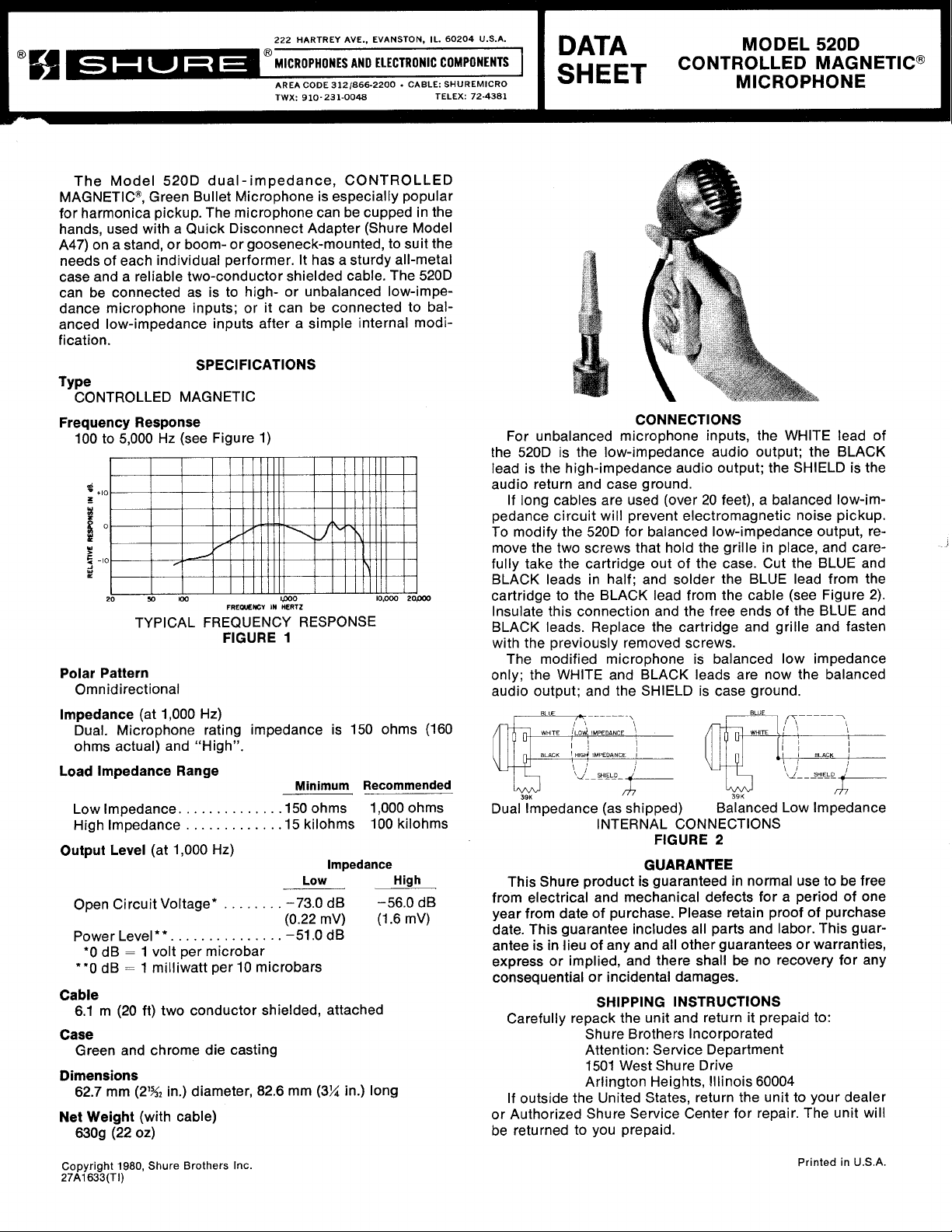
The Model 520D dual-impedance, CONTROLLED
MAGNETICB, Green Bullet Microphone is especially popular
for harmonica pickup. The microphone can be cupped in the
hands, used with a Quick Disconnect Adapter (Shure Model
A47) on a stand, or boom- or gooseneck-mounted, to suit the
needs of each individual performer. It has a sturdy all-metal
case and a reliable two-conductor shielded cable. The 520D
can be connected as is to high- or unbalanced
dance microphone inputs; or it can be connected to balanced low-impedance inputs after a simple internal modification.
SPECIFICATIONS
Type
CONTROLLED MAGNETIC
Frequency Response
100 to 5,000 Hz (see Figure 1)
d
*
+I0
I
-
AND
ELECTRONIC
low-impe-
COMPONENTS
1.
W
5
-10
Y
L
20
50
I00
TYPICAL FREQUENCY RESPONSE
Polar Pattern
Omnidirectional
lmpedance
Dual. Microphone rating impedance is 150 ohms (160
ohms actual) and "High".
Load lmpedance Range
Low lmpedance.
High lmpedance
Output Level
Open Circuit Voltage*
Power Level**.
'0 dB = 1 volt per microbar
**0 dB = 1 milliwatt per 10 microbars
Cable
6.1 m (20 ft) two conductor shielded, attached
Case
Green and chrome die casting
Dimensions
62.7 mm (2% in.) diameter, 82.6 mm
Net
Weight
6309 (22 02)
(at 1,000 Hz)
(at 1,000 Hz)
. . .
(with cable)
FREQLENCV
FIGURE
. . . . . . . .
. . . . . .
. . . . . .
. . . .
. . .
.
.
lpO0 10,000
IN
HERTZ
1
Minimum Recommended
. .
. .
.I50 ohms
.I5 kilohms
. . . .
-73.0
(0.22
. . . . . .
-51.0 dB
2opoO
1,000 ohms
100 kilohms
lmpedance
Low High
dB
mV) (1.6 mV)
(3%
-56.0 dB
in.) long
MODEL 520D
CONTROLLED MAGNETICB
1
1
:!gT
CONNECTIONS
For unbalanced microphone inputs, the WHITE lead of
the 520D is the low-impedance audio output; the BLACK
lead is the high-impedance audio output; the SHIELD is the
audio return and case ground.
If long cables are used (over 20 feet), a balanced
pedance circuit will prevent electromagnetic noise pickup.
To modify the 520D for balanced low-impedance output, re-
move the two screws that hold the grille in place, and care-
OLJ~
fully take the cartridge
BLACK leads in half; and solder the BLUE lead from the
cartridge to the BLACK lead from the cable (see Figure 2).
Insulate this connection and the free ends of the BLUE and
BLACK leads. Replace the cartridge and grille and fasten
with the previously removed screws.
The modified microphone is balanced low impedance
only; the WHITE and BLACK leads are now the balanced
audio output; and the SHIELD is case ground.
-
- - - -
-.
39K
Dual lmpedance (as shipped)
INTERNAL CONNECTIONS
This Shure product is guaranteed in normal use to be free
from electrical and mechanical defects for a period of one
year from date of purchase. Please retain proof of purchase
date. This guarantee includes all parts and labor. This guarantee is in lieu of any and all other guarantees or warranties,
express or implied, and there shall be no recovery for any
consequential or incidental damages.
SHIPPING INSTRUCTIONS
Carefully repack the unit and return it prepaid to:
Shure Brothers Incorporated
Attention: Service Department
1501 West Shure Drive
Arlington Heights,
If outside the United States, return the unit to your dealer
or Authorized Shure Service Center for repair. The unit will
be returned to you prepaid.
of the case. Cut the BLUE and
FIGURE
GUARANTEE
MICROPHONE
low-im-
BLUE
,
Balanced Low lmpedance
2
Illinois 60004
IT------
I
Copyright
27A1633(TI)
1980,
Shure
Brothers
Inc.
Printed
in
U.S.A.
Page 2
REPLACEMENT PARTS
Cartridge
Cable
Rubberplug
Accessory Resonator
......................................
......................................
..................................
........................
R44D
70A2047
66A174
.90A3051
OPTIONAL ACCESSORIES
Quick Disconnect Adapter
Gooseneck (6,12, or 18 in.)
Gooseneck Mounting Flange
........................
................
.G6, G12, GI8
......................
.A47
.A12
AMATEUR RADIO USAGE
The Model 520D is ideal for amateur radio contests. The
microphone can be VOX- or footswitch operated. The
YE"-27
thread at the bottom of the case permits wall- or tablemounting using standard-threaded microphone accessories.
Suggested accessories are the Shure 6-, 12-, and 18-inch
goosenecks (Models G6, G12, and
mounting flange (Model
B
SW-1
boom-swivel mount.
A12); and the Atlas Sound Model
G18); and gooseneck
CONNECTIONS
The WHITE lead of the 520D is the low-impedance audio
output; the BLACK lead is the high-impedance audio output; the SHIELD is the audio return and case ground. Most
transmitters with a 3-conductor phone jack audio input use
the tip for the keying circuit, the ring for the audio, and the
sleeve for the ground.
Connect the microphone to a phone plug as follows:
either
the WHITE or BLACK lead of the 520D to the ring (depending
on whether low or high impedance is required); the 520D
SHIELD to the sleeve. This is for VOX operation.
If a footswitch is used, connect the switch "hot" lead to
the phone jack tip and the switch shield to the sleeve.
V
FIGURE
3
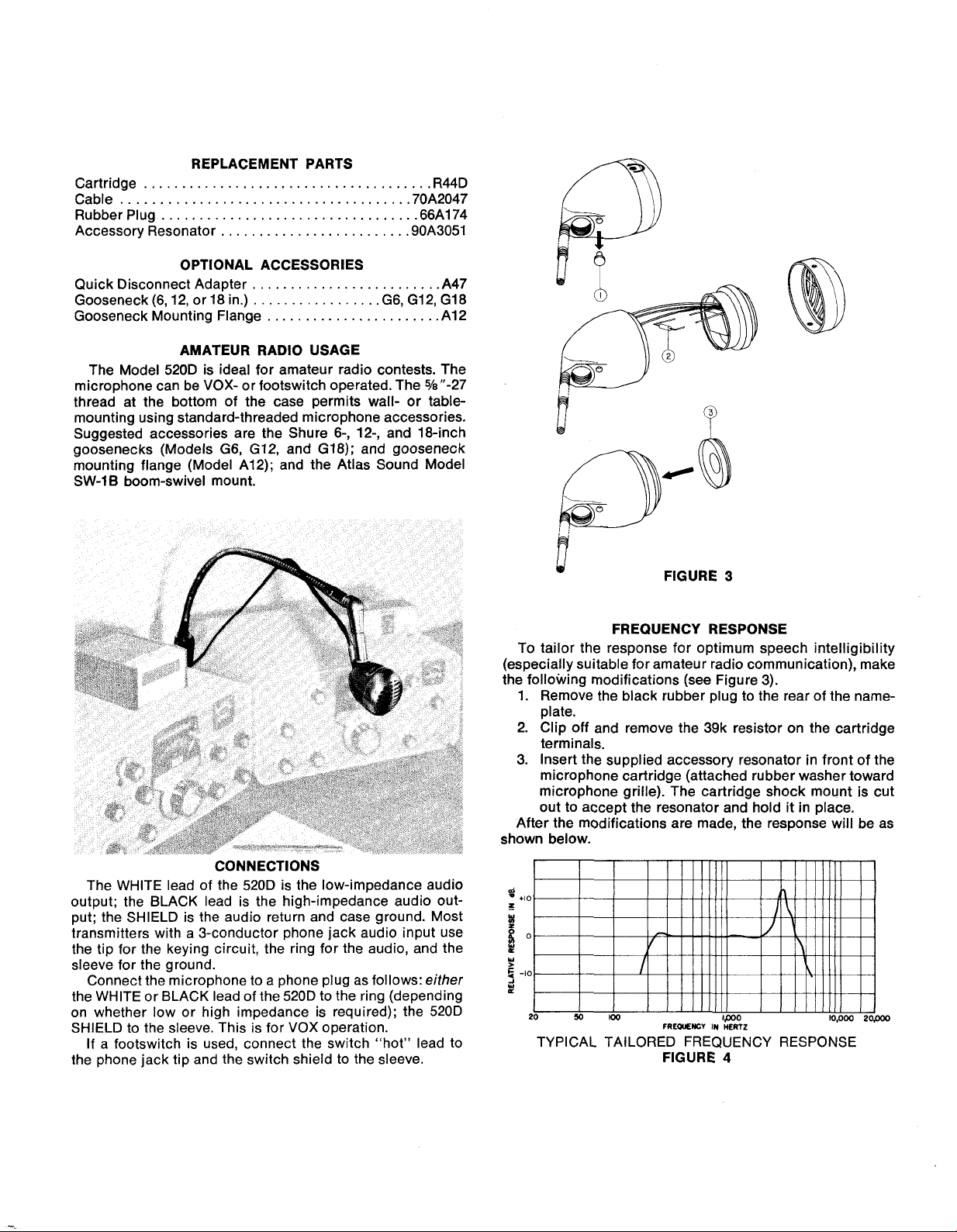
FREQUENCY RESPONSE
To tailor the response for optimum speech intelligibility
(especially suitable for amateur radio communication), make
the following modifications (see Figure 3).
1.
Remove the black rubber plug to the rear of the nameplate.
2. Clip off and remove the 39k resistor on the cartridge
terminals.
3.
Insert the supplied accessory resonator in front of the
microphone cartridge (attached rubber washer toward
microphone grille). The cartridge shock mount is cut
out to accept the resonator and hold it in place.
After the modifications are made, the response will be as
shown below.
=
+I0
5
I
s
o
w
5
-I0
2
W
20 50
ma
FREWENCV
IN
lpo0
HERTZ
lo.000
24000
TYPICAL TAILORED FREQUENCY RESPONSE
FIGURE
4
 Loading...