

Page 1
i
222
AREA
TWX:
HARTREY
AVE.,
CODE
312/866-2200
910-231-0048
EVANSTON.
.
CABLE:
IL.
60204
SHUREMICRO
TELEX:
UNIDIRECTIONAL DYNAMIC MICROPHONES
GENERAL
The Shure Models
DYNE'?
B Microphones are low-impedance units designed specifically for flexible gooseneck application.
The microphones are moving coil units providing good
reproduction of music and voice.
These microphones are particularly suitable for use
in language lab systems, paging applications, and
base station communications. They are highly recommended for
talkback and cuing from professional
control rooms in TV, film, and recording studios, and
other uses demanding a customized installation with
concealed cables.
Features:
True cardioid pickup pattern: symmetrical about
axis and uniform at all frequencies
Response especially effective for announcing,
narration, paging and music
Cartridge shock-mounted for quiet operation
R
Built-in, non-locking, push-to-talk switch controls both microphone circuit and relay or
control circuit
R
Dependability and ruggedness under all operating conditions
A 457 mm (18 in.) flexible gooseneck and a convenient mounting flange supplied with the Model
5SB-GI 8
51
To mount the
having a
5/8"-27
microphone (see Figure 1-A), remove adjacent thin
metal washer and one metal spacer from terminating
end of cable. Slide the thin metal washer removed
previously onto cable up into end of microphone. Slip
gooseneck over cable and install into end of micro-
phone.
515SBG and 515SB-GI8 UNI-
MOUNTING
515SBG microphone on a gooseneck
thread, unscrew black end cap from
U.S.A.
DATA
SHEET
72-4381
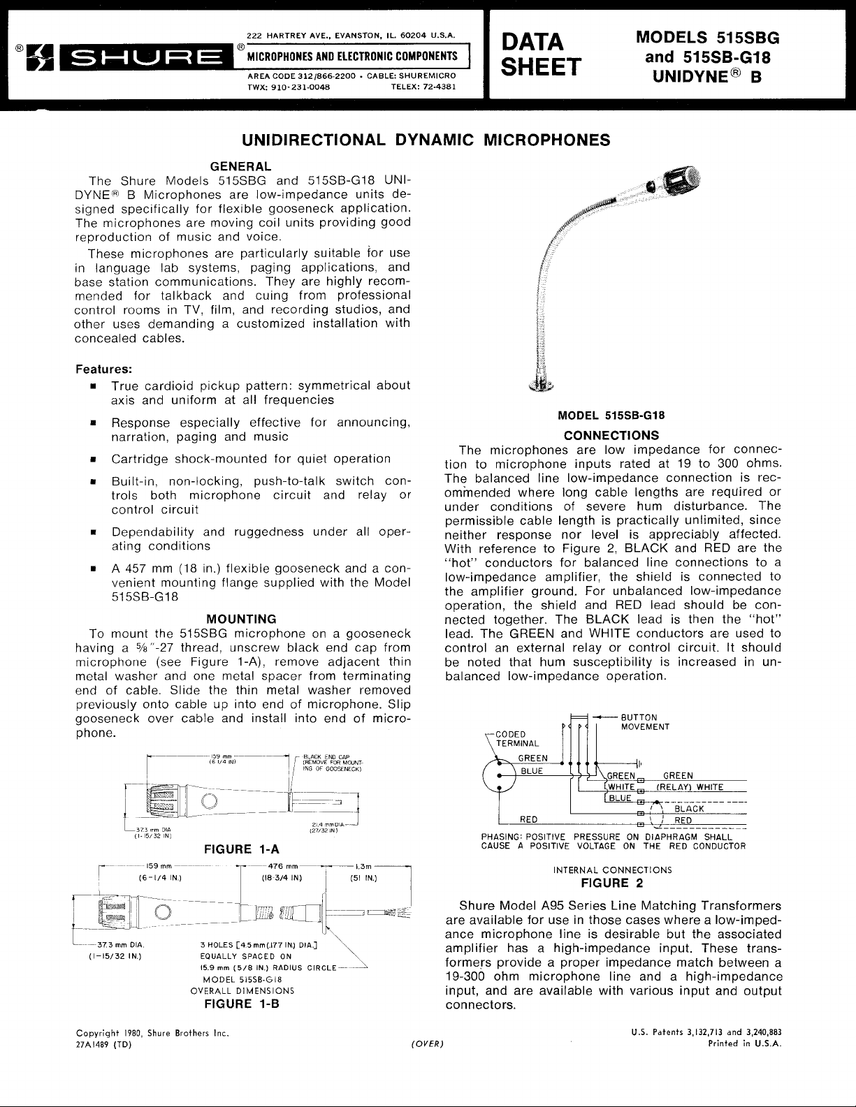
MODEL
MODELS
and
UNIDYNE~
515SB-GI8
515s~~
515SB-GI8
CONNECTIONS
The microphones are low impedance for connec-
tion to microphone inputs rated at 19 to
300
The balanced line low-impedance connection is recommended where long cable lengths are
required or
under conditions of severe hum disturbance. The
permissible cable length is practically unlimited, since
neither response nor level is appreciably affected.
2,
With reference to Figure
BLACK and RED are the
"hot" conductors for balanced line connections to a
low-impedance amplifier, the shield is connected to
the amplifier ground. For unbalanced low-impedance
operation, the shield and RED lead should be connected together. The BLACK lead is then the "hot"
lead. The
GREEN
and WHITE conductors are used to
control an external relay or control circuit. It should
be noted that hum susceptibility is increased in un-
balanced low-impedance operation.
BUTTON
.;-CODED
TERMINAL
GREEN
MOVEMENT
B
ohms.
L
373mm
(1-15/32
Copyright
27A1489
L373
1980,
(TD)
,,
(1-5/32 IN1
159
(6-114
OIA
IN)
Shure
Dl,
mm
---
IN)
Brothers
FIGURE 1-A
-
T
3
HOLES
[45mm(177
EQUALLY
159
OVERALL
mm
(5/8
MODEL
515SB-Gi8
DIMENSIONS
FIGURE
Inc.
SPACED
--
(18
IN)
1-B
476
mm-
3/4
IN)
ON
RADIUS
IN)
127/32
DlA]
CIRCLE
- - -
- -
-
- - - - -
-
'
BLACK
,
!
:
RED
&
IN
1
1
3m
PHASING:
CAUSE
POSITIVE
A
POSITIVE
PRESSURE
VOLTAGE ON
INTERNAL
CONNECTIONS
FllGURE
ON
DIAPHRAGM
THE
2
-------
RED
CONDUCTOR
-.
____-_
SHALL
Shure Model A95 Series Line Matching Transformers
are available for use in those cases where a
low-imped-
ance microphone line is desirable but the associated
amplifier has a high-impedance input. These trans-
-
formers provide a proper impedance match between a
a
19-300 ohm microphone line and
high-impedance
input, and are available with various input and output
connectors.
U.S.
Patents
3,132,713
and
3,240,883
Printed
in
(OVER)
U.S.A.
Page 2
Important: Shure microphone cables are selected
after exhaustive tests to insure superior performance
in microphones because of low capacities, superior
shielding properties and unusually long life under
severe use.
Cables with plastic insulation should not be subjected to excessive soldering-iron heat. Carefully clean
and tin the conductors and
the connections to which
the conductors are to be soldered. The soldering
operation can then be done with a minimum of heat,
thereby avoiding any possibility of damage to the
cable.
ARCHITECTS' SPECIFICATION
The microphone shall be the Shure Model
515SBG,
515SB-GI8 or equivalent. The microphone shall be a
moving coil (dynamic) microphone with a frequency
response of 80 to 13,000 Hz. This unit shall have a
cardioid polar characteristic. The cancellation at the
sides shall be approximately 6 dB, and the cancellation at the rear shall be 15 to 20 dB. The microphone
shall be low impedance with a rated impedance of 150
ohms for connection to microphone inputs rated at
19 to 300 ohms. The microphone output shall be
-60 dB where
The microphone shall be equipped with a built-in,
0 dB = 1 milliwatt with 10 microbars.
non-
locking, push-to-talk switch.
The Model
a gooseneck having a
shall have a
515SBG shall be suitable for mounting on
%"-27 thread. The microphone
1.8m (70 in.) four-conductor (two shielded)
cable. The overall microphone dimensions shall be
159 mm (6-1/4 in.) in length and 37.3 mm (1-15/32 in.)
in diameter.
The Model
515SB-GI8 shall be mounted on a flexible
gooseneck having a mounting flange. The microphone
shall have a
1.3m (51 in.) four-conductor (two shielded)
cable extending from the gooseneck. The overall di-
mensions shall be 635 mm (25 in.) in length and
37.3 mm (1-15/32 in.) in diameter.
FIGURE
Microphone Impedance
170 ohms actual
Microphone Rating Impedance
150 ohms for connection to microphone inputs rated
at 19 to 300 ohms
Output Level (at 1000 Hz)
Open Circuit Voltage
(0 dB = 1 volt per microbar)
.
Power Level
(0 dB = 1
. . . . . . . .
milliwatt with 10 microbars)
Switch
Built-in, leaf-type, non-locking, push-to-talk
Shock Mount
Internal rubber vibration-isolator
Cable
Highly durable cable with effective hum shielding,
four conductors (two shielded), plastic-jacketed
Model
Model
515SBG-1.8-meter (70 in.)
515SB-G18-1.3 meters (51 in.)
from gooseneck
Case
Silver finish die casting with black
4
. . . . . . . .
.
. .
.
. . . .
. .
-82 dB (.080 mV)
-60 dB
grille and stainless steel screen
SPEClFlCATlONS
Type
Dynamic
Frequency Response
Hz
80 to 13,000
m
9+10
Z
w
Z
p
0
w
w
5-,o
w
rn
I
PO
I
M
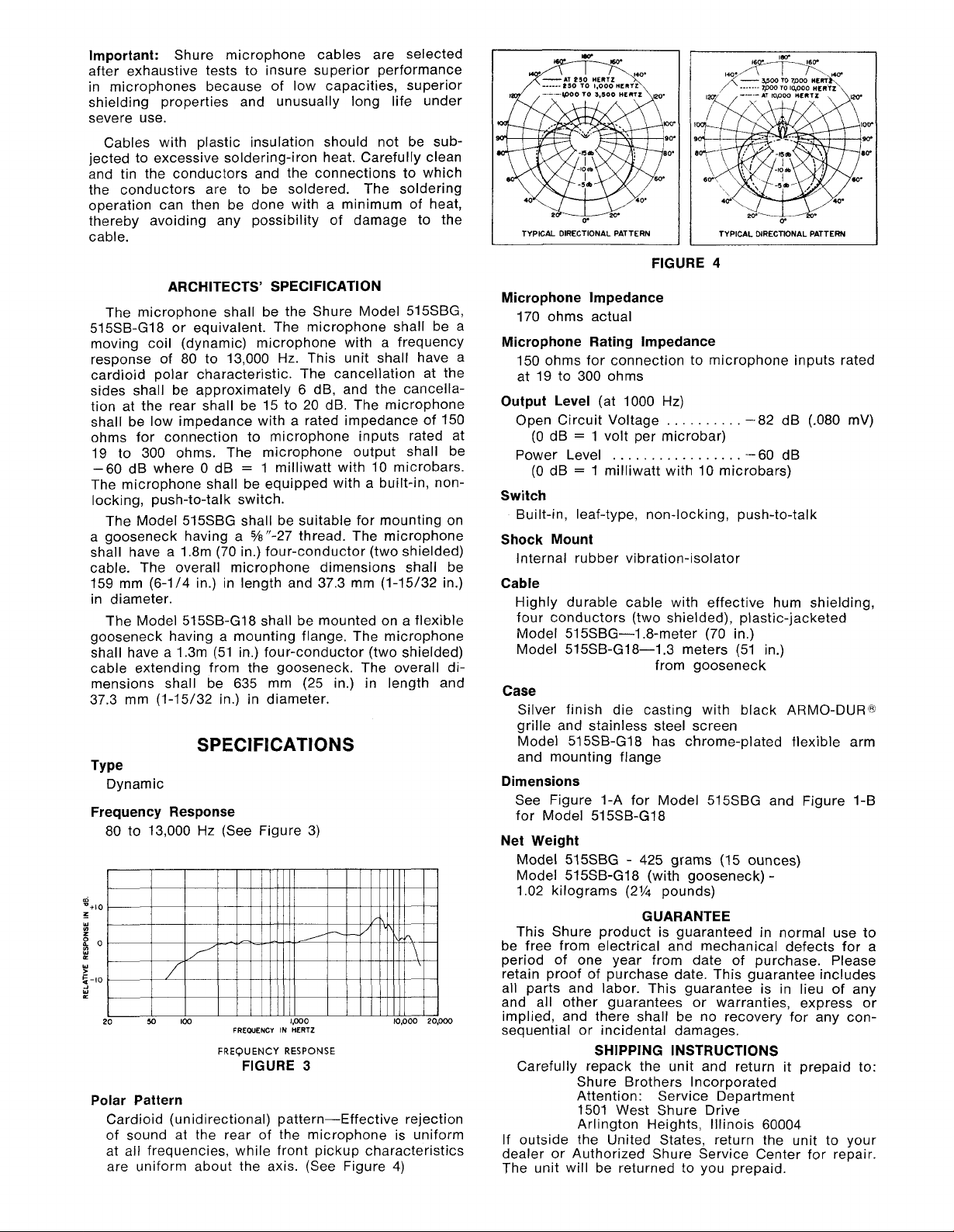
Polar Pattern Attention: Service ~epartment
Cardioid (unidirectional) pattern-Effective rejection
of sound at the rear of the microphone
frequencies, while front pickup characteristics
at all
are uniform about the axis. (See Figure 4)
(See Figure 3)
I I I I I Illll
100
FREWENCY IN HERTZ
FREQUENCY
RESPONSE
FIGURE
1,000
I
3
I I IIIIII I J
l0,OOO
20.000
is uniform
Model 515SB-GI8 has chrome-plated flexible arm
and mounting flange
Dimensions
See Figure I-A for Model
515SBG and Figure 1-B
for Model 515SB-G18
Net Weight
Model
Model
515SBG
515SB-GI8 (with gooseneck)
-
425
grams (15 ounces)
-
1.02 kilograms (2% pounds)
GUARANTEE
This Shure product is guaranteed in normal use to
be free from electrical and mechanical defects for a
period of one year from date of purchase. Please
retain proof of purchase date. This guarantee includes
all parts and labor. This guarantee is in lieu of any
and all other guarantees or warranties, express or
implied, and there shall be no recovery for any consequential or incidental damages.
SHIPPING INSTRUCTIONS
Carefully repack the unit and return it prepaid to:
Shure Brothers
lncor~orated
1501 West Shure Drive
Arlington Heights, Illinois 60004
lf
outside the United States, return the unit to your
dealer or Authorized Shure Service Center for repair,
The unit will be returned to you prepaid.
ARMO-DUR@
 Loading...